EP0438829B1 - Method of producing a plate-shaped product comprising positioning a component which is connected to or forms part of a plate, and also device suitable for carrying out the method and plate-shaped product which can be manufactured according to the method - Google Patents
Method of producing a plate-shaped product comprising positioning a component which is connected to or forms part of a plate, and also device suitable for carrying out the method and plate-shaped product which can be manufactured according to the method Download PDFInfo
- Publication number
- EP0438829B1 EP0438829B1 EP90203397A EP90203397A EP0438829B1 EP 0438829 B1 EP0438829 B1 EP 0438829B1 EP 90203397 A EP90203397 A EP 90203397A EP 90203397 A EP90203397 A EP 90203397A EP 0438829 B1 EP0438829 B1 EP 0438829B1
- Authority
- EP
- European Patent Office
- Prior art keywords
- plate
- component
- bearing
- support
- die
- Prior art date
- Legal status (The legal status is an assumption and is not a legal conclusion. Google has not performed a legal analysis and makes no representation as to the accuracy of the status listed.)
- Expired - Lifetime
Links
- 238000000034 method Methods 0.000 title claims abstract description 47
- 230000005489 elastic deformation Effects 0.000 claims abstract description 43
- 210000000080 chela (arthropods) Anatomy 0.000 claims description 33
- 238000006073 displacement reaction Methods 0.000 claims description 27
- 238000010276 construction Methods 0.000 claims description 17
- 230000002706 hydrostatic effect Effects 0.000 claims description 12
- 230000001105 regulatory effect Effects 0.000 claims description 12
- 239000012530 fluid Substances 0.000 claims description 10
- 230000005484 gravity Effects 0.000 claims description 9
- 238000010008 shearing Methods 0.000 claims description 8
- 238000001125 extrusion Methods 0.000 claims description 3
- 230000001276 controlling effect Effects 0.000 claims description 2
- 238000003825 pressing Methods 0.000 claims description 2
- 230000007246 mechanism Effects 0.000 description 19
- 230000006835 compression Effects 0.000 description 3
- 238000007906 compression Methods 0.000 description 3
- 238000006243 chemical reaction Methods 0.000 description 2
- 238000004519 manufacturing process Methods 0.000 description 2
- 239000000463 material Substances 0.000 description 1
- 238000007665 sagging Methods 0.000 description 1
- 238000003466 welding Methods 0.000 description 1
Images


Classifications
-
- B—PERFORMING OPERATIONS; TRANSPORTING
- B23—MACHINE TOOLS; METAL-WORKING NOT OTHERWISE PROVIDED FOR
- B23P—METAL-WORKING NOT OTHERWISE PROVIDED FOR; COMBINED OPERATIONS; UNIVERSAL MACHINE TOOLS
- B23P21/00—Machines for assembling a multiplicity of different parts to compose units, with or without preceding or subsequent working of such parts, e.g. with programme control
-
- B—PERFORMING OPERATIONS; TRANSPORTING
- B23—MACHINE TOOLS; METAL-WORKING NOT OTHERWISE PROVIDED FOR
- B23P—METAL-WORKING NOT OTHERWISE PROVIDED FOR; COMBINED OPERATIONS; UNIVERSAL MACHINE TOOLS
- B23P19/00—Machines for simply fitting together or separating metal parts or objects, or metal and non-metal parts, whether or not involving some deformation; Tools or devices therefor so far as not provided for in other classes
- B23P19/02—Machines for simply fitting together or separating metal parts or objects, or metal and non-metal parts, whether or not involving some deformation; Tools or devices therefor so far as not provided for in other classes for connecting objects by press fit or for detaching same
- B23P19/027—Machines for simply fitting together or separating metal parts or objects, or metal and non-metal parts, whether or not involving some deformation; Tools or devices therefor so far as not provided for in other classes for connecting objects by press fit or for detaching same using hydraulic or pneumatic means
-
- B—PERFORMING OPERATIONS; TRANSPORTING
- B21—MECHANICAL METAL-WORKING WITHOUT ESSENTIALLY REMOVING MATERIAL; PUNCHING METAL
- B21D—WORKING OR PROCESSING OF SHEET METAL OR METAL TUBES, RODS OR PROFILES WITHOUT ESSENTIALLY REMOVING MATERIAL; PUNCHING METAL
- B21D22/00—Shaping without cutting, by stamping, spinning, or deep-drawing
- B21D22/02—Stamping using rigid devices or tools
- B21D22/04—Stamping using rigid devices or tools for dimpling
-
- Y—GENERAL TAGGING OF NEW TECHNOLOGICAL DEVELOPMENTS; GENERAL TAGGING OF CROSS-SECTIONAL TECHNOLOGIES SPANNING OVER SEVERAL SECTIONS OF THE IPC; TECHNICAL SUBJECTS COVERED BY FORMER USPC CROSS-REFERENCE ART COLLECTIONS [XRACs] AND DIGESTS
- Y10—TECHNICAL SUBJECTS COVERED BY FORMER USPC
- Y10T—TECHNICAL SUBJECTS COVERED BY FORMER US CLASSIFICATION
- Y10T29/00—Metal working
- Y10T29/53—Means to assemble or disassemble
- Y10T29/53039—Means to assemble or disassemble with control means energized in response to activator stimulated by condition sensor
- Y10T29/53061—Responsive to work or work-related machine element
-
- Y—GENERAL TAGGING OF NEW TECHNOLOGICAL DEVELOPMENTS; GENERAL TAGGING OF CROSS-SECTIONAL TECHNOLOGIES SPANNING OVER SEVERAL SECTIONS OF THE IPC; TECHNICAL SUBJECTS COVERED BY FORMER USPC CROSS-REFERENCE ART COLLECTIONS [XRACs] AND DIGESTS
- Y10—TECHNICAL SUBJECTS COVERED BY FORMER USPC
- Y10T—TECHNICAL SUBJECTS COVERED BY FORMER US CLASSIFICATION
- Y10T83/00—Cutting
- Y10T83/141—With means to monitor and control operation [e.g., self-regulating means]
- Y10T83/148—Including means to correct the sensed operation
-
- Y—GENERAL TAGGING OF NEW TECHNOLOGICAL DEVELOPMENTS; GENERAL TAGGING OF CROSS-SECTIONAL TECHNOLOGIES SPANNING OVER SEVERAL SECTIONS OF THE IPC; TECHNICAL SUBJECTS COVERED BY FORMER USPC CROSS-REFERENCE ART COLLECTIONS [XRACs] AND DIGESTS
- Y10—TECHNICAL SUBJECTS COVERED BY FORMER USPC
- Y10T—TECHNICAL SUBJECTS COVERED BY FORMER US CLASSIFICATION
- Y10T83/00—Cutting
- Y10T83/525—Operation controlled by detector means responsive to work
- Y10T83/536—Movement of work controlled
Definitions
- the invention relates to a method for positioning a component which is connected to or forms part of a plate.
- the invention also relates to a device suitable for carrying out the method.
- a component can rather be considered as a part of a plate or as a discrete element.
- the component is a part of the plate this part has to be deformed in order to take its desired position.
- the die is intended to mean a deforming member.
- the component is a discrete element connected to the plate the die does not deform anything but only changes the position of a discrete element with respect to the plate so the die is intended to mean an element positioning member.
- a method and device of the type mentioned in claims 1 and 16 are generally known in the form of a compression device provided with a top and bottom die.
- a plate is placed on the bottom die, and the top die is then pressed against the plate in such a way that the plate deforms permanently.
- the plate will not only deform plastically, but a certain elastic deformation of the plate will also occur.
- the plate After lifting of the top die the plate will spring back to some extent as a result of the elastic energy in the plate. This means that the final shape of the plate differs slightly from the shape of the dies.
- a chassis plate in which the mounting faces for the components to be fitted are positioned accurately relative to each other is known from European Patent Application EP 0 184 159 A2.
- the chassis plate is cast, and the mounting faces are finished in one setting.
- the disadvantage of this chassis plate is that the manufacture thereof is very laborious, and is therefore also expensive.
- the cast structure also means that the plate is heavy and the material costs are high.
- the object of the invention is, inter alia, to provide a method in which components of or on a plate can be positioned in a simple manner and with very great accuracy, so that finishing operations on the plate or readjustments of the components to be fitted are no longer necessary.
- a further object of the invention is to provide a device by means of which the envisaged method can be carried out in an advantageous manner.
- the invention is characterized in that the plate is placed on a bearing, a reference plane is defined relative to three points of the plate, during positioning of the component its height relative to the reference plane is measured by a measuring means producing an output signal, the output signal is compared with a reference signal, the difference between the output and the reference signal is used to produce a control signal for displacement of the die and/or the support and in that during positioning the plate is kept free from elastic deformations by keeping the resulting force from the forces exerted by the die and the support on the plate equal to zero. Not clamping the plate between two die faces, but allowing it to rest on a bearing ensures that no elastic deformations can occur here in the plate on account of shape deviations of the plate.
- Measuring the position of the component relative to the reference plane means that it is possible to establish the degree to which the force exerted on the plate by, or the position relative to the plate of, the die and the support has to be altered to obtain the correct position of the component relative to the reference plane.
- Said control signal is generated e.g. by comparators.
- the comparators compare the output signal of measuring means with a reference signal and send control signals to the amplifiers to displace the die. If during the positioning of the component by means of the die and the support no resulting force is exerted on the plate, the plate will also not be elastically deformed outside the support. This means that there will also be no question of springback when the die and the support are removed, so that the position of the component is maintained.
- An embodiment of the method according to the invention is characterized in that elastic deformations of the plate (20, 64) are detected and are reduced to zero by regulating the force in or the position of the support (8; 70-73) during the positioning of the component. This means that as soon as elastic deformations occur in the plate they can be eliminated by changing the force in or the position of the support in such a way that compensation for the causes of the elastic deformation of the plate takes place.
- Another embodiment of the method according to the invention is characterized in that elastic deformations of the plate are detected by measuring the forces in the bearing. This is a simple method of detecting the presence of elastic deformations in a plate.
- Another embodiment of the method according to the invention is characterized in that elastic deformations of the plate are detected by the displacement of the plate relative to the bearing. This is another simple method of detecting the presence of elastic deformations in a plate.
- Yet another embodiment of the method according to the invention is characterized in that during the positioning of the component, the force in or the position of the support is regulated until the above-mentioned forces are essentially zero, or until the above-mentioned displacement is essentially zero. If these forces are zero or this displacement is zero, no more elastic deformations can be present in the plate, as a result of which no springback of the plate can therefore occur either and the position of the component is maintained.
- Another embodiment of the method according to the invention is characterized in that during the positioning of the component the plate is supported only by two bearing points and by the support, so that during the positioning of the component no elastic deformation of the plate can occur.
- exerting a force on the plate at the position of one of the points (formed by the support) ensures that said force is borne fully by that point (support) and no reaction forces occur in the other two points. This also means that no stresses can occur in the plate outside the above-mentioned point (support).
- a further embodiment of the method according to the invention is characterized in that the positioning takes place by pressing the component, which is formed by an element, through an aperture in the plate, said element being clamped by a wall of the aperture.
- the position of an element for example a tape guide or a stationary magnetic head, can be positioned accurately in height. This makes height adjustment by means of an adjusting mechanism unnecessary.
- Yet another embodiment of the method according to the invention is characterized in that the positioning takes place by plastic deformation of the plate locally so that a plate part is moved relative to the reference plane, the component being formed by the above-mentioned plate part.
- a mounting face can be provided in a plate with very great accuracy. It is possible to fit thereon, for example, a scanning unit of a video recorder or a motor of a capstan, the position of which must be known very accurately.
- a related embodiment of the method according to the invention is characterized in that the plastic deformation takes place by stretching of the plate. Due to the fact that this stretching takes place very locally, namely only at the support, the elastic deformation of the plate is very small in this case and the springback of the plate is negligible.
- Another related embodiment of the method according to the invention is characterized in that the plastic deformation takes place through shearing in the plate. During shearing the plate is almost exclusively plastically deformed. As a result, after positioning of the component virtually no springback of the deformed part occurs, and the position will be maintained very accurately.
- Yet another related embodiment of the method according to the invention is characterized in that the plastic deformation takes place through upsetting of the plate.
- the plate can be made thinner locally. This is an advantage if an element is being fixed on the plate at the position of the component by means of laser welding. The side of the plate facing away from the element to be fitted is in this case heated locally by a laser, thereby producing a welded joint. With a lower thickness of the plate at the joint to be formed less energy is needed, which means that fewer stresses also occur in the plate.
- Yet another related embodiment of the method according to the invention is characterized in that the plastic deformation occurs through extrusion of the plate.
- a component for example a capstan branch connection, can be formed in the plate in a simple and accurate manner.
- a further embodiment of the method according to the invention is characterized in that the reference plane is determined by measuring the positions of bearing points of the bearing, in which case a plane through the bearing points forms the reference plane. If the bearing comprises three bearing points, this means that for each plate, regardless of the deviations as a result of shape tolerances, a component of or on the plate can be positioned with very great accuracy relative to the three points present on the plate.
- Yet another embodiment of the method according to the invention is characterized in that various components are positioned after one another in terms of time. This has great advantages if different components of which the positions relative to one another have to be very accurate have to be fitted on the plate.
- the relative positions of the components are often the only important factor, and not the positions of the components relative to the plate. This is the case with, for example, a video recorder, where only the relative positions of the tape guides are important.
- the desired relative positions are obtained by fitting each component accurately relative to a reference plane.
- the positions of the components are determined relative to a reference plane through the plate and not relative to the plate itself, since in the latter case the positions of the components relative to each other might be incorrect, owing to the shape tolerances of the plate.
- a related embodiment of the method according to the invention is characterized in that a further reference plane is determined by positioning three components so that a plane through reference points on these components forms the further reference plane for the remaining components to be positioned thereafter.
- a plane through reference points which are present, for example, on the first three positioned components and which serve, for example, as mounting faces for a scanning unit of a video recorder ensures that the position of these components need not be so accurate. They can, for example, all be present in the plate beforehand.
- the components to be fitted thereafter then in turn do have to be fitted with great accuracy relative to the reference plane. In this way the mutual positions of the parts are achieved even more accurately.
- the invention is defined by the features set out in claim 16.
- the position of the component can be measured with this device.
- the control system can control the die and the support in order to obtain the desired position of the component. Due to the fact that in the device the main frame to which the die and the support are fixed and the auxiliary frame on which the bearing is located are separated from each other, the working forces cannot influence the bearing. With the above-mentioned means, finally, it can be ensured that elastic deformations of the plate, as a result of a load exerted by the die, are eliminated. This can take place only if the bearing of the plate does not result in a statically overdetermined situation. As a result of a statically overdetermined situation elastic deformations can occur in the plate.
- An embodiment of the device according to the invention is characterized in that the above-mentioned means comprise the control system and a regulator of the control system controls the support.
- the elastic deformations in the plate can be influenced by changing the position of or the force in the support, and can even be totally removed by means of a suitable regulation.
- a further embodiment of the device according to the invention is characterized in that the device also comprises measuring means for, when the above-mentioned plate is present, measuring the displacement of the plate relative to the reference plane.
- the presence of elastic deformations in the plate can be detected in this way. No elastic deformations are introduced into the plate through the bearing. If the plate is now displaced at the position of the support, which can take place through the fact that the die exerts a force on the plate, elastic deformations will be present in the plate. Thus so long as a displacement not equal to zero is measured, the control system will have to ensure that the displacement is removed by, for example, adapting the position of the support.
- Yet another embodiment of the device according to the invention is characterized in that the bearing is formed by three bearing points, and said device also comprises measuring means for measuring the force in at least one of the bearing points.
- the bearing is formed by three bearing points
- said device also comprises measuring means for measuring the force in at least one of the bearing points.
- the presence of elastic deformations in the plate can be detected.
- no elastic stresses can be introduced into the plate, due to the three-point bearing. If a force is measured here in a bearing point, this force can be transmitted only via the plate, so that elastic stresses must be present in the plate. As long as this force is not equal to zero, elastic deformations will be present in the plate, and the control system will have to eliminate them.
- Another embodiment of the device according to the invention is characterized in that the above-mentioned means comprise two bearing points and the support.
- the plate By placing the plate on two bearing points and the support and making the load by the die act on the plate at the position of the support, the plate cannot deform elastically either as a result of the bearing or as a result of the load.
- the control system can be simplified as a result of this.
- An embodiment of the device according to the invention is characterized in that the device also comprises a sub-frame, provided with three further bearing points on which the plate can rest, which sub-frame rests on the two bearing points present on the auxiliary frame, and which device also comprises measuring means for measuring the position of the component and of the sub-frame relative to an external reference.
- the control system now needs only to regulate that the correct position of the component relative to the reference plane is obtained. This is possible by regulating that the position of the sub-frame, which also determines the position of the reference plane, remains constant, and that the desired position of the component is achieved.
- Yet another embodiment of the device according to the invention is characterized in that the die and the support form part of a pincer construction which has a centre of gravity and is supported, at the centre of gravity, on bearings on the main frame and in that the said means for keeping the resulting force equal to zero comprises the said bearing.
- an embodiment of the device which is a further development of the above is characterized in that the said bearing comprises a hydrostatic bearing having a fluid inlet and outlet aperture, which apertures are located in that part of the bearing which is stationary and attached to the main frame.
- a further embodiment of the device which is a further development of the above is characterized in that the pincer construction comprises a hydraulic cylinder having fluid inlet and outlet lines which, at the location of further fluid inlet and outlet apertures located in the movable part of the hydrostatic bearing, are coupled with the hydrostatic bearing, the inlet and outlet apertures being in connection, via ducts through the bearing, with the further inlet and outlet apertures.
- the pincer construction comprises a hydraulic cylinder having fluid inlet and outlet lines which, at the location of further fluid inlet and outlet apertures located in the movable part of the hydrostatic bearing, are coupled with the hydrostatic bearing, the inlet and outlet apertures being in connection, via ducts through the bearing, with the further inlet and outlet apertures.
- An embodiment of the device according to the invention is characterized in that the device comprises at least one hydraulic cylinder for displacing the die and/or the support. Great forces can be applied in a readily controllable and regulatable manner by means of a hydraulic cylinder.
- the device comprises a movable arm on which the die and the support are situated. This means that by displacement of the arm various components can be positioned on one plate with one die/support combination.
- Yet another embodiment of the device according to the invention is characterized in that the device comprises various dies and supports and has various hydraulic cylinders for displacement of the dies and the supports. This also has the advantage that various components can be positioned on a plate as a result.
- Yet another embodiment of the device according to the invention is characterized in that the auxiliary frame is displaceable relative to the main frame. This also means that various components can be positioned on one plate with one die/support combination.
- FIG. 1 shows schematically a first embodiment of a device by which a method according to the invention can be carried out.
- the device comprises a main frame 2 to which two hydraulic cylinders 4 and 6 are fixed for the displacement of a support 8 and a die 10.
- the device also comprises an auxiliary frame 12, provided with a bearing 14, for example comprising three bearing points 16, 18 (two of which are shown) for bearing a plate 20.
- a component 22 of the plate 20 can be deformed by means of the die 10, which interacts with the support 8.
- the measuring means being a linear transducer that measures the displacement and which produces an output signal.
- This displacement is regulated by a control system comprising a comparator 24 and an amplifier 25, which maintains the component 22 in the desired position relative to the reference plane 26 during the process.
- the comparator 24 compares the output signal from the measuring means 19 with a reference signal, generated by a source 28, representing the value of measuring means 19 when the die 10 is at its desired position. The difference between these signals is sent to the amplifier 25 which produces a control signal to displace the die 10 by means of cylinder 6.
- the control system comprises a further comparator 30 and a further amplifier 31 and the device is provided with further measuring means 32 being a linear transducer for measuring the distance a of the plate 20.
- the elastic deformations are now removed from the plate by moving the support 8 in such a way that there is compensation for the sag of the main frame 2.
- the distance a of the plate 20 relative to the reference plane 26 is measured using the measuring means 32, and the support 8 is displaced until the distance is equal to the distance before the component 22 is positioned. If in the situation of Figure 1 (the plate 20 rests on three bearing points 16, 18) the distance a of the plate to the reference plane 26 at any place other than the bearing points is equal to the corresponding distance in the beginning i.e. before the component 22 is positioned and a force is exercised on the plate, so the displacement of the plate at that place is zero, then the displacement of any other place of the plate also has to be zero. So detecting that distance a is the same as in the beginning has the same result as stating that the plate 20 is free of any stresses.
- the displacement of the support 8 is regulated by the control system in the same way as the displacement of the die 10 is regulated.
- the displacement of the support 8 can in turn result in the die 10 being shifted slightly as a result of sagging of the main frame 2.
- the control system compensates for this movement.
- Figure 2 shows schematically a second embodiment, which differs from the embodiment described above in that the elastic deformations in the plate are detected by measuring the force in the bearing.
- the device comprises measuring means 34 for measuring the force in one of the bearing points 18. If the force in one of the bearing points is zero, it follows from the moment equilibrium that the forces in the other bearing points must also be zero, from which it then follows that no elastic deformations are present in the plate.
- the device not only a part of the plate can be deformed by the device in order to position a component 22 of the plate but also a separate component 23, in this example a pin, can be positioned on the plate.
- Figures 3a and 3b show a third embodiment of the device, in which the occurrence of elastic deformations in the plate is avoided by means which support the plate at three points.
- Figure 3b shows a part of a sectional view of the device shown in Figure 3a parallel to the plane of the drawing and behind elements 36 and 54.
- the principle of this embodiment is that when a plate is supported on three points only and no forces are exercised on the plate at places other than those three points then no stresses can occur in the plate.
- the plate 20 itself is not directly beared on the main frame but support 8 fixed on the main frame (not shown) supports the plate 20 on one point and the main frame has two bearing points 36 and 38 supporting a sub-frame 40 comprising three further bearing points 42, 44 (two of which are shown) on which the plate is clamped by means of clamps 54, 56 and 58.
- the main frame now sags, as a result of the reaction forces of the die and the support on the main frame, no elastic deformations occur in the plate, but the plate and thus also the sub-frame will be displaced.
- the support 8 can be displaced by means of a control element comprising a comparator 48 and an amplifier 49.
- the comparator compares the output signal of the measuring means 46, which may be a linear transducer, with a reference signal, generated by source 52, representing the value of the measuring means 46 when the sub-frame is not displaced.
- the difference between these signals is sent to the amplifier 49 which produces a control signal to displace the support 8 by means of the cylinder 4.
- the reference plane 26 relative to an external reference 50, and thus also the position of the plate relative to the die and the support, retain their position.
- the correct position of the component 22 can also be obtained by means of said control system.
- control system comprising a further comparator 49 and a further amplifier 51.
- Figure 4 shows a device with which different components 118, 119, 120 and 122 of or on a plate 64 can be positioned.
- the device comprises various dies 66, 67, 68 and 69 and supports 70, 71, 72 and 73.
- the dies are fixed to a top distributor plate 74, and the supports are fixed to a bottom distributor plate 76.
- the distributor plates are each connected to a piston 79, 81 which is hydraulically displaceable in directions of arrows A in a main cylinder 78, 80.
- the main cylinders are fixed to a main frame 82 of the device.
- the device also has an auxiliary frame 84 on which three bearing points 86, 88 (two of which are shown) are situated for bearing the plate.
- the dies and the supports can each be retracted individually relative to each other. In this way all dies and supports can be brought into a retracted position 90 and each die/support combination can then be brought in succession temporarily into a working position 92 moved towards each other. In the working position a component of the plate or on the plate can then be positioned by controlling the hydraulic main cylinders 78, 80 in the same way as cylinders 4, 6 of Figures 1 and 2 are controlled.
- each distributor plate 74, 76 has on it a hydraulic auxiliary cylinder 96, 98 which can be set at an angle relative to the distributor plate.
- the die 67 and the support 71 are displaceable in these auxiliary cylinders.
- the auxiliary cylinders 96, 98 now also have to be controlled.
- the auxiliary cylinders can be moved in a circular path in order thus to position various components of or on the plate part.
- the device shown in Figure 4 also comprises a control system for the positioning of the components and measuring means 61, 62, 63 and 65 for measuring the positions of the pistons 79, 81, the die 67 and the support 71.
- This control system comprises four slave control systems each comprising a comparator 102, 104, 106 and 108 and an amplifier 91, 93, 95 and 97 and each system regulating the pressure in a main or auxiliary cylinder until it is equal to a desired value.
- a master control system comprising a comparator 110, 112, 114 and 116 comparing an output signal generated by measuring means 60a and 60b with a reference signal generated by a source 100a, 100b, 100c and 100d, four of these master control systems are present in the control system.
- Two of these comparators 110 and 112 ensure that if elastic stresses occur in the plate they are reduced to zero.
- the force is measured in one of the bearing points 88. If this force is not equal to zero, the plate therefore exerts a force on the bearing point, so that the plate therefore must be under stress.
- the force in the bearing point can be reduced to zero by regulating the force in the support 70 when it is in the working position.
- the forces in one of the three bearing points are zero, the forces in the other two bearing points are also zero, so that no elastic stress can therefore be present in the plate.
- the force in the support is regulated by the pressure in the bottom main and/or auxiliary cylinder 80, 9 8 respectively.
- Two other comparators 114 and 116 ensure that the component assumes the desired position relative to a reference plane through the plate. The position of the component is not determined relative to the plate 64 because the shape of the plate is subject to tolerances. The plane through the three bearing points is taken as the reference plane through the plate. It is a question of ensuring that all components assume the correct positions relative to each other, which amounts to the same as the components assuming the correct positions relative to an external reference.
- the position of the component to be positioned is measured relative to the external reference, to which reference the bearing points are also connected.
- This external reference is formed by the auxiliary frame 84.
- the master controls 114 and 116 regulate the pressure in the top main and/or auxiliary cylinder 78, 96 respectively, so that the die assumes the correct position and the component thus also reaches its correct position.
- the components 118, 120 need not always be a part of the plate 64, but can also be loose elements 122 which are pressed through apertures in the plate.
- Component 122 is formed by a pin 122 which is pressed into an aperture in the plate. The component 122 is taken to the correct height with the aid of the die 66.
- Figure 5 shows a fourth embodiment of a device with which a method according to the invention can be carried out.
- the die 130 and the support 132 are each situated on a part 134, 136 of a pincer mechanism 138.
- the two ends 140, 142 of the parts can be moved towards each other or away from each other by means of a hydraulic cylinder 144 and are pivotable relative to each other about a point of rotation 146.
- the pincer mechanism 138 comprises the cylinder 144, the support 132 and the die 130 and is supported in its centre of gravity 147, for example by means of a ball bearing 148.
- the bearing 148 is connected to a main frame 150.
- the bearing 148 of the pincer mechanism 138 in this embodiment thus forms part of the means which ensure that the plate is free from elastic deformations.
- the position of the support 132 is measured with the aid of measuring means 154, here in the form of a dial indicator.
- the position of the component 156 can be determined from the position of the support. Depending on this position of the component 156, the cylinder is controlled by means of a control system comprising a comparator 158 and an amplifier 159.
- the comparator 158 compares an output signal of the measuring means 154 with a reference signal generated by a source 157 and the difference is sent to the amplifier 159 on the same way as is described in the description of Figure 1. It is possible also to control the cylinder manually if necessary.
- the bearing of the plate 152 is formed by supports 160, 162 which are connected to an auxiliary frame 164.
- elastic deformations can still occur in the plate during simultaneous positioning of various parts, even though no force is measured in a bearing point, or even though no displacement is measured at a point.
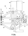
- various pincer mechanisms 138, 166, 167, 168, 169 are fitted on the main frame as shown in Figure 6.
- the plate In order to position various components after one another on a plate with the device shown in Figure 5, the plate must be displaceable relative to the pincer mechanism.
- One possibility for this is that the plate can be placed in various positions on the supports. Another possibility is to fit the bearing on a mobile arm which is then fixed to the main frame. Yet another possibility is to displace the plate relative to the pincer mechanism in order to make the auxiliary frame and the main frame displaceable relative to each other.
- Figure 7 shows an embodiment in which both the main frame 170 and the auxiliary frame 172 are displaceable relative to an external reference 174.
- the pincer mechanism 180 is provided with a suitable mechanism 182 and a connecting rod 184 in order to move the two parts 176 and 178 of the pincer mechanism 180 far enough away from each other during the displacement.
- the external reference 174 is provided with a support 186 on which the main frame 172 can be placed in order to position components on the plate at an angle with the plane of the plate 188.
- Figure 8 shows the situation in which the auxiliary frame 172 is placed at an angle. In this position, it is possible to position, for example, components of the plate which act as mounting faces for mounting a scanning unit of a video recorder.
- Figure 8a shows another embodiment of the pincer construction 300 which is also supported on bearings in its centre of gravity 302.
- the point of rotation 304 for the two pincer parts 338 and 350 and the location for the hydraulic cylinder 306 are moved, as a result of which no extra mechanisms and connecting rod are needed to be able to open the pincer construction sufficiently.
- the bearing is constructed as a hydrostatic, virtually friction-free, bearing 308 to ensure that it is not possible for a resulting force to be exerted on the plate as a result of friction in the bearing. This is because, should there be friction in the bearing, this can then result in the transfer of a moment, which can lead to a force on the plate.
- the lines 310 and 312 for the inlet to and outlet from the hydraulic cylinder 306 are coupled to the movable part 314 of the hydrostatic bearing 308, as a result of which no external forces can be exerted on the pincer construction 300 via the lines.
- Figure 8b shows the construction of the hydrostatic bearing 308, with connection apertures 316, 318, 320 and 322 for external lines and for the lines 310 and 312 coming from the hydraulic cylinder 306.
- connection apertures 316 and 318 in the fixed parts 340 and 342 of the bearing can be connected to the connection apertures 316 and 318 in the fixed parts 340 and 342 of the bearing, which apertures are in connection, via ducts 324 and 326 present in the bearing shaft 328, with the connection apertures 320 and 322 for connection of the lines 310 and 312 from and to the hydraylic cylinder 306.
- Some of the fluid passes via further ducts 330 and 332 to fluid chambers 334 and 336 for the hydrostatic bearing.
- the movable part 314 of the bearing is rigidly connected to the lowermost part 338 of the pincer construction and the fixed parts 340 and 342 of the bearing are connected to the main frame 334.
- the support 346 and the die 348 are located at the free ends of the pincer parts 338 and 350, as can be seen in Figure 8a.
- a cylindrical jaw 352 is present in the support 346 and is coupled with measuring means 354 for determining the position for the component to be positioned.
- the measuring means 354 are fixed to an auxiliary frame 356.
- the hydraulic cylinder 306 is fixed on the uppermost part 350 of the pincer construction and is provided, via a control valve 358, with fluid for moving the pincer parts 338 and 350 relative to one another.
- piston 360 of the cylinder 306 is connected via a connecting hose 362 to the lowermost part 338 of the pincer construction.
- Figure 9 shows a part of a plate-shaped product comprising a plate 200 of which a component 206 is positioned.
- the plate 200 is provided with apertures 202 and 204 on both sides of a plate part 205.
- the plate part 205 comprises a central plate part 206 which forms the component, and connecting plate parts 208 and 210 which connect the central plate part 206 to the remainder of the plate 200.
- the component 206 is positioned by shearing the central plate part 206 relative to the connecting plate parts 208 and 210. This is recognizable on the plate 200 by the presence of shearing zones 212 and 214.
- Figure 10 shows a plate part 215 in which a component 216 is positioned by stretching connecting plate parts 318 and 320 so that stretch zones 222 and 224 are produced.
- Figure 11 shows the plate part 205 during the positioning of a component of the plate. Shear occurs in the plate part 205 through moving die 226 and support 228 towards each other. The position of the component is measured by means of a plug guage 230 which is fitted in the support 228.
- Figure 12 shows a plate part 232 in which a component 234 is positioned by upsetting the plate.
- a reference point 235 is situated on the side of the component 234 facing a die 236.
- a support 238 is situated at the other side of the component with a greater diameter than that of the die 236.
- Figure 13 shows a last example of a component 242 of a plate 240 which is positioned by means of a die 244 and a support 246.
- the component 242 is upset and a reference point 243 is formed by a top face of an upset wall of the component 242.
- Figure 14 shows a plate-shaped product comprising a plate 250 in which components 268, 270 and 272 of the plate and components 252 and 254 are positioned relative to each other as elements pressed into apertures 256 and 258 in the plate.
- the elements 252 and 254 are positioned first and are clamped by walls 260 and 262 in the plate 250.
- a plane 267 through reference points 264 and 266 on the two elements shown and on a third element not shown forms a reference plane 267 for the components 268, 270 and 272 to be positioned after this.
- These components are placed at desired distances a 1 , a 2 and a 3 from the reference plane 267.
Landscapes
- Engineering & Computer Science (AREA)
- Mechanical Engineering (AREA)
- Bending Of Plates, Rods, And Pipes (AREA)
- Shaping Metal By Deep-Drawing, Or The Like (AREA)
- Casting Or Compression Moulding Of Plastics Or The Like (AREA)
- Shaping Of Tube Ends By Bending Or Straightening (AREA)
- Electrical Discharge Machining, Electrochemical Machining, And Combined Machining (AREA)
- Perforating, Stamping-Out Or Severing By Means Other Than Cutting (AREA)
- Automatic Assembly (AREA)
- Blow-Moulding Or Thermoforming Of Plastics Or The Like (AREA)
- Injection Moulding Of Plastics Or The Like (AREA)
- Moulds For Moulding Plastics Or The Like (AREA)
Applications Claiming Priority (2)
| Application Number | Priority Date | Filing Date | Title |
|---|---|---|---|
| NL9000152A NL9000152A (nl) | 1990-01-22 | 1990-01-22 | Werkwijze voor het positioneren van een onderdeel, dat verbonden is met of een deel vormt van een plaat, alsmede inrichting geschikt voor het uitvoeren van de werkwijze en plaat vervaardigbaar volgens de werkwijze. |
| NL9000152 | 1990-01-22 |
Publications (3)
| Publication Number | Publication Date |
|---|---|
| EP0438829A2 EP0438829A2 (en) | 1991-07-31 |
| EP0438829A3 EP0438829A3 (en) | 1991-11-13 |
| EP0438829B1 true EP0438829B1 (en) | 1997-03-26 |
Family
ID=19856461
Family Applications (1)
| Application Number | Title | Priority Date | Filing Date |
|---|---|---|---|
| EP90203397A Expired - Lifetime EP0438829B1 (en) | 1990-01-22 | 1990-12-18 | Method of producing a plate-shaped product comprising positioning a component which is connected to or forms part of a plate, and also device suitable for carrying out the method and plate-shaped product which can be manufactured according to the method |
Country Status (12)
| Country | Link |
|---|---|
| US (1) | US5168737A (cs) |
| EP (1) | EP0438829B1 (cs) |
| JP (1) | JP3032022B2 (cs) |
| KR (1) | KR100193122B1 (cs) |
| AT (1) | ATE150685T1 (cs) |
| CS (1) | CS11191A2 (cs) |
| DE (1) | DE69030307T2 (cs) |
| ES (1) | ES2102359T3 (cs) |
| HK (1) | HK1006432A1 (cs) |
| MY (1) | MY105451A (cs) |
| NL (1) | NL9000152A (cs) |
| RU (1) | RU1838018C (cs) |
Families Citing this family (6)
| Publication number | Priority date | Publication date | Assignee | Title |
|---|---|---|---|---|
| US5537734A (en) * | 1995-01-30 | 1996-07-23 | Western Atlas, Inc. | Press |
| JPH1196640A (ja) * | 1997-09-26 | 1999-04-09 | Matsushita Electric Ind Co Ltd | ディスク装置 |
| US6223573B1 (en) * | 1999-06-25 | 2001-05-01 | General Electric Company | Method for precision temperature controlled hot forming |
| TW201438883A (zh) * | 2013-04-11 | 2014-10-16 | Wistron Corp | 整形裝置與機箱的整形方法 |
| CN109454432B (zh) * | 2018-12-27 | 2021-05-04 | 宁波博睿智能设备科技有限公司 | 一种胶皮梳的自动组装机 |
| CN113878313B (zh) * | 2021-11-01 | 2024-05-17 | 无锡亿臻机械有限公司 | 高速织机用新型连杆支撑结构制作方法 |
Family Cites Families (10)
| Publication number | Priority date | Publication date | Assignee | Title |
|---|---|---|---|---|
| DE2305283C3 (de) * | 1973-02-02 | 1980-02-21 | G. Siempelkamp Gmbh & Co, 4150 Krefeld | Verfahren und Vorrichtung zum Messen der bleibenden Durchbiegung eines Werkstückes bei einer Blechbiegepresse |
| IT1097410B (it) * | 1978-07-26 | 1985-08-31 | Galdabini Renzo | Macchina per il raddrizzamento automatico di pezzi allungati |
| DE3333666A1 (de) * | 1983-09-17 | 1985-04-04 | Skf Kugellagerfabriken Gmbh, 8720 Schweinfurt | Verfahren und vorrichtung zum zusammenbau von kreuzgelenken |
| EP0166351A3 (de) * | 1984-06-27 | 1986-09-17 | Arnold Stucki | Vorrichtung an einer Maschine für Umformarbeiten an blechförmigen Materialien |
| EP0184159B1 (de) * | 1984-11-29 | 1994-01-19 | PAPST-MOTOREN GmbH & Co. KG | Integriertes Antriebssystem für Festplattenspeicher |
| JPH0773752B2 (ja) * | 1986-07-31 | 1995-08-09 | 松下電器産業株式会社 | パンチング装置 |
| US4802357A (en) * | 1987-05-28 | 1989-02-07 | The Boeing Company | Apparatus and method of compensating for springback in a workpiece |
| EP0299111B1 (de) * | 1987-07-13 | 1994-06-01 | Wilhelm Hegenscheidt Gesellschaft mbH | Verfahren und Einrichtung zum Richten von Schlag aufweisenden Werkstücken |
| DE3741855A1 (de) * | 1987-12-10 | 1989-06-22 | Opel Adam Ag | Verfahren zur spanabhebenden bearbeitung eines bauteiles sowie spannteil zu seiner durchfuehrung |
| US5062283A (en) * | 1988-07-19 | 1991-11-05 | Yamazaki Mazak Kabushiki Kaisha | Press brake and a workpiece measuring method in the press brake |
-
1990
- 1990-01-22 NL NL9000152A patent/NL9000152A/nl not_active Application Discontinuation
- 1990-12-18 ES ES90203397T patent/ES2102359T3/es not_active Expired - Lifetime
- 1990-12-18 AT AT90203397T patent/ATE150685T1/de active
- 1990-12-18 EP EP90203397A patent/EP0438829B1/en not_active Expired - Lifetime
- 1990-12-18 DE DE69030307T patent/DE69030307T2/de not_active Expired - Fee Related
-
1991
- 1991-01-17 US US07/642,740 patent/US5168737A/en not_active Expired - Fee Related
- 1991-01-18 CS CS91111A patent/CS11191A2/cs unknown
- 1991-01-18 RU SU914894151A patent/RU1838018C/ru active
- 1991-01-19 MY MYPI91000089A patent/MY105451A/en unknown
- 1991-01-19 KR KR1019910000874A patent/KR100193122B1/ko not_active Expired - Fee Related
- 1991-01-21 JP JP3021689A patent/JP3032022B2/ja not_active Expired - Lifetime
-
1998
- 1998-06-12 HK HK98105221A patent/HK1006432A1/en not_active IP Right Cessation
Also Published As
| Publication number | Publication date |
|---|---|
| JP3032022B2 (ja) | 2000-04-10 |
| MY105451A (en) | 1994-10-31 |
| NL9000152A (nl) | 1991-08-16 |
| DE69030307T2 (de) | 1997-09-18 |
| CS11191A2 (en) | 1991-08-13 |
| RU1838018C (ru) | 1993-08-30 |
| US5168737A (en) | 1992-12-08 |
| DE69030307D1 (de) | 1997-04-30 |
| EP0438829A3 (en) | 1991-11-13 |
| ES2102359T3 (es) | 1997-08-01 |
| KR100193122B1 (ko) | 1999-06-15 |
| EP0438829A2 (en) | 1991-07-31 |
| KR910014176A (ko) | 1991-08-31 |
| ATE150685T1 (de) | 1997-04-15 |
| JPH04217434A (ja) | 1992-08-07 |
| HK1006432A1 (en) | 1999-02-26 |
Similar Documents
| Publication | Publication Date | Title |
|---|---|---|
| KR100230167B1 (ko) | 굽힘가공기 | |
| US5901426A (en) | Method of combining workpieces | |
| US4936126A (en) | Press brake with a displacement sensor of electric signal output | |
| EP0438829B1 (en) | Method of producing a plate-shaped product comprising positioning a component which is connected to or forms part of a plate, and also device suitable for carrying out the method and plate-shaped product which can be manufactured according to the method | |
| RU2018386C1 (ru) | Способ установки валков универсальной прокатной клети | |
| GB2076722A (en) | Method and apparatus for regulating preselected loads on forming dies | |
| US4457684A (en) | Hydraulic press | |
| US4470787A (en) | Hydraulic press | |
| HK1006432B (en) | Method of producing a plate-shaped product comprising positioning a component which is connected to or forms parts of a plate, and also device suitable for carrying out the method and plate-shaped product which can be manufactured according to the method | |
| US11020786B2 (en) | System for controlling the restraining force applied to a panel during a drawing operation | |
| CA2017347A1 (en) | Method and arrangement for automatically aligning a universal rolling mill stand after the stand has been changed to new types of sections | |
| JPH08164500A (ja) | 分散加圧型プレス装置 | |
| US4238718A (en) | Process and equipment for the production of semi-finished sections of accurate weight or volume for cold working or hot forming | |
| US5478225A (en) | Tool set type powder compacting press | |
| JPH0446680B2 (cs) | ||
| EP1277529B1 (en) | Bending method and bending apparatus | |
| US6742440B2 (en) | Servo-controlled integral stop for use with a servo-controlled hydraulic piston | |
| US5644939A (en) | Straightening machine for rolled beams | |
| US20020078729A1 (en) | Multi-high roll stand | |
| JP2921342B2 (ja) | プレス機械のスライド高さ調整方法 | |
| JPH06185968A (ja) | 構造物の変形検出器 | |
| JP3519104B2 (ja) | プレスブレーキ | |
| JP4322976B2 (ja) | 曲げ荷重制御方式による曲げ加工方法および曲げ加工機 | |
| JP2000264652A (ja) | 光学素子の成形装置および成形方法 | |
| JPS63174725A (ja) | 電気信号アウトプツトの変位センサ付プレスブレ−キ |
Legal Events
| Date | Code | Title | Description |
|---|---|---|---|
| PUAI | Public reference made under article 153(3) epc to a published international application that has entered the european phase |
Free format text: ORIGINAL CODE: 0009012 |
|
| AK | Designated contracting states |
Kind code of ref document: A2 Designated state(s): AT DE ES FR GB IT |
|
| PUAL | Search report despatched |
Free format text: ORIGINAL CODE: 0009013 |
|
| AK | Designated contracting states |
Kind code of ref document: A3 Designated state(s): AT DE ES FR GB IT |
|
| 17P | Request for examination filed |
Effective date: 19920513 |
|
| 17Q | First examination report despatched |
Effective date: 19921109 |
|
| GRAG | Despatch of communication of intention to grant |
Free format text: ORIGINAL CODE: EPIDOS AGRA |
|
| GRAH | Despatch of communication of intention to grant a patent |
Free format text: ORIGINAL CODE: EPIDOS IGRA |
|
| GRAH | Despatch of communication of intention to grant a patent |
Free format text: ORIGINAL CODE: EPIDOS IGRA |
|
| GRAA | (expected) grant |
Free format text: ORIGINAL CODE: 0009210 |
|
| AK | Designated contracting states |
Kind code of ref document: B1 Designated state(s): AT DE ES FR GB IT |
|
| REF | Corresponds to: |
Ref document number: 150685 Country of ref document: AT Date of ref document: 19970415 Kind code of ref document: T |
|
| REF | Corresponds to: |
Ref document number: 69030307 Country of ref document: DE Date of ref document: 19970430 |
|
| ITF | It: translation for a ep patent filed | ||
| ET | Fr: translation filed | ||
| REG | Reference to a national code |
Ref country code: ES Ref legal event code: FG2A Ref document number: 2102359 Country of ref document: ES Kind code of ref document: T3 |
|
| PGFP | Annual fee paid to national office [announced via postgrant information from national office to epo] |
Ref country code: AT Payment date: 19971219 Year of fee payment: 8 |
|
| PGFP | Annual fee paid to national office [announced via postgrant information from national office to epo] |
Ref country code: ES Payment date: 19971223 Year of fee payment: 8 |
|
| PLBE | No opposition filed within time limit |
Free format text: ORIGINAL CODE: 0009261 |
|
| STAA | Information on the status of an ep patent application or granted ep patent |
Free format text: STATUS: NO OPPOSITION FILED WITHIN TIME LIMIT |
|
| 26N | No opposition filed | ||
| REG | Reference to a national code |
Ref country code: FR Ref legal event code: CD |
|
| PG25 | Lapsed in a contracting state [announced via postgrant information from national office to epo] |
Ref country code: AT Free format text: LAPSE BECAUSE OF NON-PAYMENT OF DUE FEES Effective date: 19981218 |
|
| PG25 | Lapsed in a contracting state [announced via postgrant information from national office to epo] |
Ref country code: ES Free format text: LAPSE BECAUSE OF NON-PAYMENT OF DUE FEES Effective date: 19991219 |
|
| PGFP | Annual fee paid to national office [announced via postgrant information from national office to epo] |
Ref country code: FR Payment date: 20011221 Year of fee payment: 12 |
|
| PGFP | Annual fee paid to national office [announced via postgrant information from national office to epo] |
Ref country code: GB Payment date: 20011224 Year of fee payment: 12 |
|
| REG | Reference to a national code |
Ref country code: GB Ref legal event code: IF02 |
|
| PGFP | Annual fee paid to national office [announced via postgrant information from national office to epo] |
Ref country code: DE Payment date: 20020220 Year of fee payment: 12 |
|
| PG25 | Lapsed in a contracting state [announced via postgrant information from national office to epo] |
Ref country code: GB Free format text: LAPSE BECAUSE OF NON-PAYMENT OF DUE FEES Effective date: 20021218 |
|
| PG25 | Lapsed in a contracting state [announced via postgrant information from national office to epo] |
Ref country code: DE Free format text: LAPSE BECAUSE OF NON-PAYMENT OF DUE FEES Effective date: 20030701 |
|
| GBPC | Gb: european patent ceased through non-payment of renewal fee |
Effective date: 20021218 |
|
| PG25 | Lapsed in a contracting state [announced via postgrant information from national office to epo] |
Ref country code: FR Free format text: LAPSE BECAUSE OF NON-PAYMENT OF DUE FEES Effective date: 20030901 |
|
| REG | Reference to a national code |
Ref country code: FR Ref legal event code: ST |
|
| REG | Reference to a national code |
Ref country code: ES Ref legal event code: FD2A Effective date: 20000114 |
|
| PG25 | Lapsed in a contracting state [announced via postgrant information from national office to epo] |
Ref country code: IT Free format text: LAPSE BECAUSE OF NON-PAYMENT OF DUE FEES;WARNING: LAPSES OF ITALIAN PATENTS WITH EFFECTIVE DATE BEFORE 2007 MAY HAVE OCCURRED AT ANY TIME BEFORE 2007. THE CORRECT EFFECTIVE DATE MAY BE DIFFERENT FROM THE ONE RECORDED. Effective date: 20051218 |