EP0436868A2 - Structure porteuse pour une façade - Google Patents
Structure porteuse pour une façade Download PDFInfo
- Publication number
- EP0436868A2 EP0436868A2 EP90124299A EP90124299A EP0436868A2 EP 0436868 A2 EP0436868 A2 EP 0436868A2 EP 90124299 A EP90124299 A EP 90124299A EP 90124299 A EP90124299 A EP 90124299A EP 0436868 A2 EP0436868 A2 EP 0436868A2
- Authority
- EP
- European Patent Office
- Prior art keywords
- post
- support frame
- seal
- strips
- frame according
- Prior art date
- Legal status (The legal status is an assumption and is not a legal conclusion. Google has not performed a legal analysis and makes no representation as to the accuracy of the status listed.)
- Granted
Links
Images


Classifications
-
- E—FIXED CONSTRUCTIONS
- E06—DOORS, WINDOWS, SHUTTERS, OR ROLLER BLINDS IN GENERAL; LADDERS
- E06B—FIXED OR MOVABLE CLOSURES FOR OPENINGS IN BUILDINGS, VEHICLES, FENCES OR LIKE ENCLOSURES IN GENERAL, e.g. DOORS, WINDOWS, BLINDS, GATES
- E06B3/00—Window sashes, door leaves, or like elements for closing wall or like openings; Layout of fixed or moving closures, e.g. windows in wall or like openings; Features of rigidly-mounted outer frames relating to the mounting of wing frames
- E06B3/54—Fixing of glass panes or like plates
- E06B3/58—Fixing of glass panes or like plates by means of borders, cleats, or the like
- E06B3/62—Fixing of glass panes or like plates by means of borders, cleats, or the like of rubber-like elastic cleats
-
- E—FIXED CONSTRUCTIONS
- E04—BUILDING
- E04B—GENERAL BUILDING CONSTRUCTIONS; WALLS, e.g. PARTITIONS; ROOFS; FLOORS; CEILINGS; INSULATION OR OTHER PROTECTION OF BUILDINGS
- E04B2/00—Walls, e.g. partitions, for buildings; Wall construction with regard to insulation; Connections specially adapted to walls
- E04B2/88—Curtain walls
- E04B2/96—Curtain walls comprising panels attached to the structure through mullions or transoms
- E04B2/962—Curtain walls comprising panels attached to the structure through mullions or transoms with angles or corners in the curtain wall
-
- E—FIXED CONSTRUCTIONS
- E06—DOORS, WINDOWS, SHUTTERS, OR ROLLER BLINDS IN GENERAL; LADDERS
- E06B—FIXED OR MOVABLE CLOSURES FOR OPENINGS IN BUILDINGS, VEHICLES, FENCES OR LIKE ENCLOSURES IN GENERAL, e.g. DOORS, WINDOWS, BLINDS, GATES
- E06B1/00—Border constructions of openings in walls, floors, or ceilings; Frames to be rigidly mounted in such openings
- E06B1/04—Frames for doors, windows, or the like to be fixed in openings
- E06B1/36—Frames uniquely adapted for windows
- E06B1/363—Bay windows
-
- E—FIXED CONSTRUCTIONS
- E06—DOORS, WINDOWS, SHUTTERS, OR ROLLER BLINDS IN GENERAL; LADDERS
- E06B—FIXED OR MOVABLE CLOSURES FOR OPENINGS IN BUILDINGS, VEHICLES, FENCES OR LIKE ENCLOSURES IN GENERAL, e.g. DOORS, WINDOWS, BLINDS, GATES
- E06B3/00—Window sashes, door leaves, or like elements for closing wall or like openings; Layout of fixed or moving closures, e.g. windows in wall or like openings; Features of rigidly-mounted outer frames relating to the mounting of wing frames
- E06B3/96—Corner joints or edge joints for windows, doors, or the like frames or wings
- E06B3/964—Corner joints or edge joints for windows, doors, or the like frames or wings using separate connection pieces, e.g. T-connection pieces
- E06B3/9642—Butt type joints with at least one frame member cut off square; T-shape joints
-
- E—FIXED CONSTRUCTIONS
- E06—DOORS, WINDOWS, SHUTTERS, OR ROLLER BLINDS IN GENERAL; LADDERS
- E06B—FIXED OR MOVABLE CLOSURES FOR OPENINGS IN BUILDINGS, VEHICLES, FENCES OR LIKE ENCLOSURES IN GENERAL, e.g. DOORS, WINDOWS, BLINDS, GATES
- E06B3/00—Window sashes, door leaves, or like elements for closing wall or like openings; Layout of fixed or moving closures, e.g. windows in wall or like openings; Features of rigidly-mounted outer frames relating to the mounting of wing frames
- E06B3/54—Fixing of glass panes or like plates
- E06B3/58—Fixing of glass panes or like plates by means of borders, cleats, or the like
- E06B3/62—Fixing of glass panes or like plates by means of borders, cleats, or the like of rubber-like elastic cleats
- E06B2003/6214—Fixing of glass panes or like plates by means of borders, cleats, or the like of rubber-like elastic cleats specially adapted for glazing bars
-
- E—FIXED CONSTRUCTIONS
- E06—DOORS, WINDOWS, SHUTTERS, OR ROLLER BLINDS IN GENERAL; LADDERS
- E06B—FIXED OR MOVABLE CLOSURES FOR OPENINGS IN BUILDINGS, VEHICLES, FENCES OR LIKE ENCLOSURES IN GENERAL, e.g. DOORS, WINDOWS, BLINDS, GATES
- E06B3/00—Window sashes, door leaves, or like elements for closing wall or like openings; Layout of fixed or moving closures, e.g. windows in wall or like openings; Features of rigidly-mounted outer frames relating to the mounting of wing frames
- E06B3/54—Fixing of glass panes or like plates
- E06B3/58—Fixing of glass panes or like plates by means of borders, cleats, or the like
- E06B3/62—Fixing of glass panes or like plates by means of borders, cleats, or the like of rubber-like elastic cleats
- E06B2003/6217—Fixing of glass panes or like plates by means of borders, cleats, or the like of rubber-like elastic cleats with specific fixing means
- E06B2003/6223—Fixing of glass panes or like plates by means of borders, cleats, or the like of rubber-like elastic cleats with specific fixing means with protruding parts anchored in grooves
-
- E—FIXED CONSTRUCTIONS
- E06—DOORS, WINDOWS, SHUTTERS, OR ROLLER BLINDS IN GENERAL; LADDERS
- E06B—FIXED OR MOVABLE CLOSURES FOR OPENINGS IN BUILDINGS, VEHICLES, FENCES OR LIKE ENCLOSURES IN GENERAL, e.g. DOORS, WINDOWS, BLINDS, GATES
- E06B3/00—Window sashes, door leaves, or like elements for closing wall or like openings; Layout of fixed or moving closures, e.g. windows in wall or like openings; Features of rigidly-mounted outer frames relating to the mounting of wing frames
- E06B3/54—Fixing of glass panes or like plates
- E06B3/58—Fixing of glass panes or like plates by means of borders, cleats, or the like
- E06B3/62—Fixing of glass panes or like plates by means of borders, cleats, or the like of rubber-like elastic cleats
- E06B2003/6217—Fixing of glass panes or like plates by means of borders, cleats, or the like of rubber-like elastic cleats with specific fixing means
- E06B2003/6229—Fixing of glass panes or like plates by means of borders, cleats, or the like of rubber-like elastic cleats with specific fixing means with grooves anchoring the cleat on a rim
-
- E—FIXED CONSTRUCTIONS
- E06—DOORS, WINDOWS, SHUTTERS, OR ROLLER BLINDS IN GENERAL; LADDERS
- E06B—FIXED OR MOVABLE CLOSURES FOR OPENINGS IN BUILDINGS, VEHICLES, FENCES OR LIKE ENCLOSURES IN GENERAL, e.g. DOORS, WINDOWS, BLINDS, GATES
- E06B3/00—Window sashes, door leaves, or like elements for closing wall or like openings; Layout of fixed or moving closures, e.g. windows in wall or like openings; Features of rigidly-mounted outer frames relating to the mounting of wing frames
- E06B3/54—Fixing of glass panes or like plates
- E06B3/58—Fixing of glass panes or like plates by means of borders, cleats, or the like
- E06B3/62—Fixing of glass panes or like plates by means of borders, cleats, or the like of rubber-like elastic cleats
- E06B2003/6238—Fixing of glass panes or like plates by means of borders, cleats, or the like of rubber-like elastic cleats having extra functions
- E06B2003/6241—Fixing of glass panes or like plates by means of borders, cleats, or the like of rubber-like elastic cleats having extra functions with drainage means
-
- E—FIXED CONSTRUCTIONS
- E06—DOORS, WINDOWS, SHUTTERS, OR ROLLER BLINDS IN GENERAL; LADDERS
- E06B—FIXED OR MOVABLE CLOSURES FOR OPENINGS IN BUILDINGS, VEHICLES, FENCES OR LIKE ENCLOSURES IN GENERAL, e.g. DOORS, WINDOWS, BLINDS, GATES
- E06B3/00—Window sashes, door leaves, or like elements for closing wall or like openings; Layout of fixed or moving closures, e.g. windows in wall or like openings; Features of rigidly-mounted outer frames relating to the mounting of wing frames
- E06B3/54—Fixing of glass panes or like plates
- E06B3/58—Fixing of glass panes or like plates by means of borders, cleats, or the like
- E06B3/62—Fixing of glass panes or like plates by means of borders, cleats, or the like of rubber-like elastic cleats
- E06B2003/6238—Fixing of glass panes or like plates by means of borders, cleats, or the like of rubber-like elastic cleats having extra functions
- E06B2003/6244—Fixing of glass panes or like plates by means of borders, cleats, or the like of rubber-like elastic cleats having extra functions with extra parts sealing against the bottom of the glazing rebate or against the edge of the pane
-
- E—FIXED CONSTRUCTIONS
- E06—DOORS, WINDOWS, SHUTTERS, OR ROLLER BLINDS IN GENERAL; LADDERS
- E06B—FIXED OR MOVABLE CLOSURES FOR OPENINGS IN BUILDINGS, VEHICLES, FENCES OR LIKE ENCLOSURES IN GENERAL, e.g. DOORS, WINDOWS, BLINDS, GATES
- E06B3/00—Window sashes, door leaves, or like elements for closing wall or like openings; Layout of fixed or moving closures, e.g. windows in wall or like openings; Features of rigidly-mounted outer frames relating to the mounting of wing frames
- E06B3/54—Fixing of glass panes or like plates
- E06B3/58—Fixing of glass panes or like plates by means of borders, cleats, or the like
- E06B3/62—Fixing of glass panes or like plates by means of borders, cleats, or the like of rubber-like elastic cleats
- E06B2003/6238—Fixing of glass panes or like plates by means of borders, cleats, or the like of rubber-like elastic cleats having extra functions
- E06B2003/6247—Fixing of glass panes or like plates by means of borders, cleats, or the like of rubber-like elastic cleats having extra functions with extra parts sealing against the fixed or another window frame
-
- E—FIXED CONSTRUCTIONS
- E06—DOORS, WINDOWS, SHUTTERS, OR ROLLER BLINDS IN GENERAL; LADDERS
- E06B—FIXED OR MOVABLE CLOSURES FOR OPENINGS IN BUILDINGS, VEHICLES, FENCES OR LIKE ENCLOSURES IN GENERAL, e.g. DOORS, WINDOWS, BLINDS, GATES
- E06B3/00—Window sashes, door leaves, or like elements for closing wall or like openings; Layout of fixed or moving closures, e.g. windows in wall or like openings; Features of rigidly-mounted outer frames relating to the mounting of wing frames
- E06B3/54—Fixing of glass panes or like plates
- E06B3/58—Fixing of glass panes or like plates by means of borders, cleats, or the like
- E06B3/62—Fixing of glass panes or like plates by means of borders, cleats, or the like of rubber-like elastic cleats
- E06B2003/625—Specific form characteristics
- E06B2003/6264—Specific form characteristics hollow
-
- E—FIXED CONSTRUCTIONS
- E06—DOORS, WINDOWS, SHUTTERS, OR ROLLER BLINDS IN GENERAL; LADDERS
- E06B—FIXED OR MOVABLE CLOSURES FOR OPENINGS IN BUILDINGS, VEHICLES, FENCES OR LIKE ENCLOSURES IN GENERAL, e.g. DOORS, WINDOWS, BLINDS, GATES
- E06B3/00—Window sashes, door leaves, or like elements for closing wall or like openings; Layout of fixed or moving closures, e.g. windows in wall or like openings; Features of rigidly-mounted outer frames relating to the mounting of wing frames
- E06B3/54—Fixing of glass panes or like plates
- E06B3/58—Fixing of glass panes or like plates by means of borders, cleats, or the like
- E06B3/62—Fixing of glass panes or like plates by means of borders, cleats, or the like of rubber-like elastic cleats
- E06B2003/625—Specific form characteristics
- E06B2003/6267—Specific form characteristics consisting of several separate parts
-
- E—FIXED CONSTRUCTIONS
- E06—DOORS, WINDOWS, SHUTTERS, OR ROLLER BLINDS IN GENERAL; LADDERS
- E06B—FIXED OR MOVABLE CLOSURES FOR OPENINGS IN BUILDINGS, VEHICLES, FENCES OR LIKE ENCLOSURES IN GENERAL, e.g. DOORS, WINDOWS, BLINDS, GATES
- E06B3/00—Window sashes, door leaves, or like elements for closing wall or like openings; Layout of fixed or moving closures, e.g. windows in wall or like openings; Features of rigidly-mounted outer frames relating to the mounting of wing frames
- E06B3/54—Fixing of glass panes or like plates
- E06B3/58—Fixing of glass panes or like plates by means of borders, cleats, or the like
- E06B3/62—Fixing of glass panes or like plates by means of borders, cleats, or the like of rubber-like elastic cleats
- E06B2003/6291—Corner arrangements
Definitions
- the invention relates to a supporting structure for or on a facade wall (and / or associated facade roof), consisting of posts that preferably run from top to bottom and preferably horizontal bars inserted between them, with posts and bars together fields for inserting and holding wall fillings or form glazing and wherein the pillar parts and transoms surrounding each field are provided with a frame-like, circumferential seal, to which the wall filling or glazing is held or fastened, the circumferential seal engaging by means of a holding foot in seal-holding grooves of the post and the transoms located on the room side (Preamble of claim 1).
- the term "facade wall” also means a corresponding facade roof.
- a supporting frame as outlined in the preamble of claim 1 above, is known from DE-PS 35 39 002, but only a vertical course of the posts and only a horizontal course of the transoms are disclosed.
- the frame-like circumferential seal is held mechanically firmly on the room side in a seal retaining groove.
- this weather seal is disadvantageously designed so that a gap remains free due to the weather-related moisture, especially rainwater can enter. On the weather side, however, there should be a perfect seal against the harmful effects of the weather.
- the seal is held there only with a further seal retaining groove approximately in the middle of the side wall of the narrow weather-side area of the transoms and the posts.
- this has the consequence that the part of the seal which extends from this seal retaining groove to the end face of the narrow areas has no hold at all on the respective profile area, ie depends more or less loosely there depending on the degree of its inherent rigidity.
- moisture can also enter in this area with the result of corresponding damage, in particular in cold weather caused by frost damage.
- the object of the invention is therefore to improve a support frame according to the preamble of claim 1 to the effect that the circumferential seal as a whole and in particular weather-side keeps moisture perfectly away from the parts to be protected and in particular prevents their penetration into the interior of the building.
- weather-side post areas and locking areas on their weather-side end faces have circumferential chambers, which serve to hold the seal in place, on the front side are limited by two spaced headers that on both sides of the profile areas with webs seals end face in end strips which are arranged and dimensioned such that they surround the front strips of the profile areas in the space between these two head strips with a snug fit , wherein the end strips with sealing action rest against each other as well as on the end faces of the front strip (characterizing part of claim 1).
- the entire narrow, weather-side area of the mullions and transoms, including the end face of this area, is completely covered by the seal, wherein entry into the area of this end face or a chamber adjoining it is avoided.
- the jamming provided there according to the invention is particularly advantageous on the weather side because of its integrity sealing and is much better than simply holding it by reaching behind an undercut.
- the invention further provides according to claim 2 that any further components of the support structure, provided that they are in the area of the circumferential seal, are matched to the design of this seal.
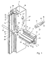
- FIGS. 10, 10a to 10c show the basic structure of a supporting frame according to the invention, the seals in FIG. 2 being recognizable and in particular FIGS. 10, 10a to 10c in particular.
- the posts 1 consist of a narrow, weather-side area 1a and a wider, room-side area 1b, which is primarily used to generate the greatest possible bending stiffness and also to connect superimposed posts (see in detail in FIG. 3 and its explanation).
- the area 1a serves to accommodate the seal.
- the transoms 2 run horizontally. They also consist of a narrow, weather-side area 2a and a warm-side and wider area 2b in the drawings.
- the mullions and transoms each form fields in which wall panels or glass panes can be inserted (see also the later explanations).
- Such a facade wall is therefore usually a load-bearing structure. In certain applications, however, it could be applied to existing structural parts.
- the transoms 2 are connected to the posts in a sliding manner and there is also a sliding connection between superposed posts (see FIG. 3) in order to be able to compensate for the different lengths of these components at different temperatures.
- the cross sections through the mullions and the transoms are the same; except for the approximately square section of area 1b located on the post and located at the rear in FIGS. 1 to 3. This results from the fact that the circumferential, frame-like seal to be explained below is always intended to surround an entire field and is therefore in contact with and held on both bars and on two posts.
- the circumferential seal 7 is designed and arranged in such a way that it is both airtight and watertight and also movements of the transoms and posts by temperature changes and the action of external loads such as wind do not impair their sealing action.
- the cross section of the seal 7 consists of a web 7 'which bears on the smooth, uninterrupted side walls of the narrow areas 2, 2a and on the one hand ends in a foot 8, which has catches 8' behind projections 4 'a retaining sealing groove 4 engages.
- end strips 30, which also have short bends 30 ′ are connected to the web ends 7 ".
- the parts 7", 30 'and 30 encompass end strips 6 and thus the end faces of the weather-side region 1a or 2a of the posts 1 or transom 2 and are held with a clamp fit in a chamber 5 whose slot opening 5' lies between the end strips 6 and opens into the end faces of the aforementioned areas 1a and 2a.
- the front strips 6 are formed on their inner walls 32 obliquely inward.
- the outer sides of the end strips 30 of the seal are correspondingly oblique (see item 34), ie the outer wall of the one end strip and that of the other end strip together form a cone tapering towards the interior of the chamber 5.
- FIG. 10 also shows the holding of an insulating glazing 67, which is held and sealed with a glazing bar 45. Furthermore, a UV radiation and weather-sensitive edge bond 68 can be provided between the panes of the glazing.
- the seal 7 with glazing bar etc. is only shown in the left half in FIG.
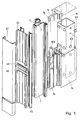
- FIGS. 11 and 12 shows one So-called expansion posts, consisting of the two halves 64 and 64 ', which are put together in the direction of arrow 64 ", as will be explained in more detail below.
- the peripheral seal carries the glazing 67 on both sides.
- the seals surrounding the fields 7 also serve to support the insulating glazing (or a corresponding panel).
- the circumferential seal 7 receives a bevel 29 (FIG. 10a) during its manufacture, which is directed like a corresponding bevel 28 of the weather-side wall of the profile 1b or 2b.
- the length of the web 7 ' is, however, dimensioned such that in the installed state (FIG. 10) the weather-side profile region 1a, 2a exerts a tension in the direction of the arrow 31 with its end strips 6. This compensates for different manufacturing tolerances of the profiles and the seals.
- Fig. 3 shows how several post profiles 1b lying flush one above the other through a connector inserted into both profiles, e.g. Steel tube 62, can be connected.
- This connecting piece is firmly connected to one of the two post profiles 1b arranged one above the other, while the other post profile can slide with its inner surface against pressure-resistant blind plugs 63 of the steel tube 62.
- the plugs 63 scrape off when inserted for the first time and thus bring about a play-free sliding connection between the parts 62 and 1b.
- a bolt 18a is provided, which belongs to the profile tube 1b, which is firmly connected to the connecting piece 62.
- the other end of the pin 18a is also accommodated in the chamber 5 of the other post 1b, which is slidably guided on the steel tube, with a sliding fit.
- a screw or pin 65 prevents the bolt 18a from sliding downward.
- FIG. 3 also shows the two Seals 7, the glazing bar 45, a pressure bar 22 and a clamping profile 57. The same arrangement is also provided for the bolts 2.
- the pressure strips 22, 22a are screwed to the end faces of the weather-side regions 1a, 2a by screws 69 (see also FIG. 11).
- the pressure bar 22, 22a engages with a central web 22 'in a groove 37 which is formed by the end bars 30 (FIGS. 10 and 10c).
- the fastening screws 69 are screwed through the middle of the pressure bar 22, 22a into the channel 37 at locations where hollow chambers 35 are located in the end bars 30. These air chambers 35 can pass through the end strips over their entire length.
- the spacing 36 of these hollow chambers 35 corresponds approximately to the diameter of the screws 69. This arrangement prevents the formation of a gap between the adjoining end strips 30 when the screws 69 are inserted.
- FIG. 10 also shows the attachment of the clamping profile 57. It engages with a protruding edge 58 (see FIG. 10b) behind a bead 59 of the respective pressure bar 22 and is in this position by striking an inner collar 61 of the clamping profile 57 on webs 60 the pressure bar 22 or 22a fixed. This leaves enough space for glazing wedges or strips 45 (see above). These wedges or strips are at least partially covered by the clamping profile 57. This is optically much cheaper than the previously usual resting of the outer leg of the glazing wedge on the clamping profile.
- filler pieces 9 and molded parts 40 are designed and arranged as described below.
- a pressure-resistant filler piece 9 is attached to the end face of the respective end of the narrow weather-side area 2a of the respective latch 2 by means of a pin 9a of the filler piece, which is inserted into the cavity 5a between two insulating webs 70 of the narrow latch area 2a with a clamping effect.
- the filler 9 has on its weather-side end face the same cross-sectional configuration as that of the narrow profile area 2a, so that there are also the end strips 30 of the seal can be inserted and clamped. In the fully assembled position according to FIG.
- the filler which is only indicated by dashed lines, abuts the side wall of the narrow, weather-side region 1a of the adjacent post.
- the seal can be guided from the narrow area 2a of the bolt over the filler piece and then bent through 90 ° over the narrow area 1a of the post and held firmly in the aforementioned areas and in the filler piece, as explained with reference to FIG. 10.
- the filler 9 does not have the warm-side or room-side widening 2b of the bolt. This makes it possible to abut the respective bar with its end face against the side wall of the box-shaped profile 1b facing it (see FIG. 2), the distance b of the aforementioned areas being bridged by the filler 9 (see FIG. 2).
- the filler thus takes over the function of the cross-sectional area 2a of the bolt in area b.
- each bolt receives a support pin 18. After inserting the respective bolt 2 transversely to its longitudinal direction into the position between two posts to be connected by it, the respective support bolt 18 is removed from the chamber 5 into the filler piece 9 and through the opening 19 of the adjacent narrow post area in the filler 9 of the transom on the other side and finally inserted into its chamber.
- the carrying bolts 18 can be limited in their movement in the longitudinal direction of the bolt by fastening screws 21 of the pressure bar 22a which can be brought in front of their ends so that a relative displacement to the respective bolt can only take place to a desired extent corresponding to the possible thermal expansion or shrinkage.
- the bolt 18 according to FIG. 1 penetrates a bore 19 of the weather-side, narrow area 1a of the adjacent post and protrudes on the other side to the extent that there is also a filler 9 (not shown) and that after left end 18 of this bolt can engage in the cavity 5 of the bolt located there.
- the joint of the pressure bar 22a of the bar 2 can be sealed against the vertically running pressure bar 22 of the post 1 by an elastic molded part 40 (FIG. 5), which is further shown on the left in FIG. 2 and on the right half in FIG. 10.
- the elastic molded part 40 has holding feet 41 which can snap into grooves 42 in the horizontally extending pressure bar 22a.
- the molded part 40 is designed in a zigzag shape according to FIG. 5 (see the solid line 43). It rests with the nose 40 'on the pressure bar 22, the elasticity of the zigzag arrangement 43 making this possible when the pressure bar 22a with molded parts 40 provided on both sides is pushed between the pressure bars 22 which have already been assembled.
- the zigzag arrangement effects a seal even in the case of tolerances in the cutting of the transom pressure bars 22a and / or assembly tolerances of the posts 1 with their pressure bars 22 or also in the case of thermally induced expansions or shrinkages.
- This can also be seen in perspective from FIG. 6.
- the lip 40 ' is otherwise shaped so that the cover strip 57 with clamping action can be inserted over the pressure bar 22 (see Fig. 10).
- the assembly sequence is such that first the pressure strip 22 of the post is screwed on, then the pressure strip 22a of the bolt is screwed on together with the molded parts 40 and finally the cover strip 57 of the pressure strip is then clamped on.
- the upper and lower edges (based on the illustration in FIG. 2) of the elastic molded part are aligned with the corresponding edges of the latch pressure bar 22a and also have end faces 44 which form a pressure area for the outer legs of the glazing bars 45.
- a corresponding molded part 40 can be provided between the pressure strips 22 of two posts 1b one above the other as shown in FIG. 3.
- the expansion joint 66 between these two pressure strips is hereby bridged and closed.
- the weather-side part 1a of the post is also covered by the seal 7, so that air and water tightness is also ensured here.
- the pressure strips 22, 22a are securely fixed due to the penetration of their web 22 'into the groove 37.
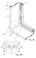
- the channels 37 are interrupted (partitioned) shortly before the cross joint 39 by transverse webs 38, which can be found both in FIG. 2 and on a larger scale in FIGS. 13a, 13b and 20, 20a. This prevents water reaching the groove 37 from reaching the cross joint 39.
- openings 47 in the pressure strips 22 can serve for this purpose, the opening width of which extends in the region of the upper edge 48 the adjacent seal is located so that water collecting on the seal is drained through the openings 47 (see Fig. 2).
- a tube 49 (FIG. 8) can be provided for the above-mentioned drainage in the rebate base, which tube is guided downward both through an opening 50 in the circumferential seal and through a corresponding opening 51 of the filler piece 9 and thus the moisture derives downwards.
- FIGS. 8 and 9 shows the detail encircled in FIG. 8 on an enlarged scale.
- the two parts 49a, 49b are joined together in the central region of the tube by means of locking cams 52 which run around in a ring.
- the outer ends of the tube parts are widened to a larger outer diameter 55 by means of bends 54. If, according to FIG.
- the opening 50 of the circumferential seal is created by a predetermined breaking point 50a, which, however, corresponds to the outer contour of the tube end 53 in a smaller diameter, the two tube parts 49a, 49b can be inserted through the opening 50 and Allow it to lock at 52 so that it is flush with the surface 56 of the circumferential seal 7.
- the dotted circles 50 in FIG. 2 show the weakened circular cross section 50a, from which the part of the seal 7 which is surrounded by it is pressed out in order to create the opening 50.
- FIG. 11 and 12 show an embodiment of the invention, in which the transoms 2 are fixedly connected to the post halves on two post halves 64 and 64 'and without the possibility of sliding.
- This fixation can be released by removing the tensioning elements.
- a fixation of the connecting element 11 in the hollow chamber 3, to be explained in more detail, is given is also releasable.
- the post half located on the right in FIG.
- post halves 64 and 64 ' can be moved to the right and left (see arrow 64 ") without the post half 64 left in FIG. 11 being moved
- Such post halves 64 and 64 ' which are movable relative to one another, permit thermal expansion and shrinkage.
- the two post halves 64, 64' form the wide, space-side region 1b (see FIG. 1). Due to their one-piece construction, the post halves 64, 64 'in The narrow, weather-side area 1a (see also FIGS. 1 and 11) is only attached to one of these two post halves, here the post half 64 '.
- the seals 7 protect both post halves 64, 64' against the ingress of Air and water, in particular this also applies to the space or gap 98 which exists between the two halves of the post and which is displaced in the direction of the arrow 64 " practices.
- the seal 7 shown on the left in FIG. 11 is guided from the narrow weather-side region of one post half 64 'past the gap 98 between the two post halves to the other post half 64.
- the cavities or chambers are sealed, which are in Fig. 11 in the lower region of the halves 64, 64 'and partially serve to accommodate the sealing feet.
- the circumferential seal 7 is thus also used at the same time for sealing the two post halves.
- the arrangement according to FIGS. 11 and 12 creates finished facade elements which are assembled at the construction site. Seals 64 "'are provided.
- the above-mentioned connecting elements 11 are initially slidably provided in the hollow chambers 3 of the wide latch part 2b, which in their longitudinal direction penetrate the entire latch and are open on the end faces of these connecting elements.
- These hollow chambers 3 are delimited on one side by the sealing retaining grooves 4 for receiving the sealing foot 8, so that the hollow chambers 3 are joined the parts 4 have a double function (receiving the holding foot of the seal and receiving the connecting elements 11).
- the basic construction of the connecting elements 11 can be seen in FIG. 1, in particular the individual illustration in FIG. 1 on the right.
- This arrangement has the essential advantage that no special precautions have to be taken for the reception of the connecting elements 11 and that in particular the wider area 2b of the bolts only has to have a depth t such that this is sufficient to form the hollow chambers 3 with sealing retaining grooves 4 that however, no other chambers, holding grooves or the like which require another space in depth need to be provided.
- the fastening of the bars 2 to the post 1 can, however, and this is a preferred embodiment of the invention, be carried out to compensate for changes in length of the parts due to temperature fluctuations, the connecting elements 11 already explained above with bolts 16 are also used.
- the connecting elements 11 are displaceably accommodated in the bars 2, specifically in their hollow chambers 3 (see right half of FIG. 1).
- the bars slide on the connecting elements.
- the posts are in one piece (see for example Fig. 1).
- the distance between two post walls, between which a transom is inserted, must be so large that it also absorbs the maximum expected length change of the transom, which is caused by an increase in temperature.
- the connecting elements 11 transfer the load of the field filling (for example glazing) from the transoms 2 to the posts 1.
- the connecting elements 11 are inserted with their bolts 16 into the recesses 12 of both walls 13, 14 of a groove 3 of the post, namely its wider post part 1b.
- the post has on both sides a groove 3 with the two walls 13, 14 and a bottom wall which has a recessed shoulder 15 which extends over the entire length of the groove 3. In the inserted position there is a flat 16 'of the bolt 16 of the connecting element 11, exactly opposite the above paragraph 15 of the groove 3.
- a resilient clamping element 17 with contact surfaces 17 ' is provided, which extends in the longitudinal direction of the respective groove 3 of the post, or to the two bolts 16 (the same connecting element 11 with bolt 16 is in the hollow chamber 3) present on the latch 2 at the bottom in FIG. 1.
- the clamping element 17, preferably a resilient sheet metal strip, lies in the fixing position with its flats 17 'on the flats 16' of the bolts 16 (see FIG. 4). In this case, the clamping element 17 engages with a middle part 17 ′′ and its two ends in the shoulder 15 of the respective groove 3.
- the bolt fastening described is provided by means of the grub screw 23
- the bolts 16 of the connecting elements 11 are fastened to the posts by means of the tensioning elements 17.
- the clamping elements 17 can with their o.g. Hold ends and the middle part 17 "in the respective groove 3 by elastic bracing between the inner sides of the groove.
- the respective bolt 2 is also carried by the weather-side bolt 18.
- the bolt 2 is slidably guided on this pin 18 and the connecting elements 11 in its longitudinal direction, whereby the above-mentioned thermal expansions can be compensated for.
- the procedure is such that the latch is first inserted transversely to its longitudinal direction with connecting elements 11 already inserted into the end face between the posts in question and then through the opening of the hollow chamber 3 with the bolts 16 into the recesses 12 between the sealing retaining grooves 4 Post walls 13, 14 is inserted. It is essential that each bolt 16 passes through only the walls 13, 14 of the adjacent groove 13; but not the walls of the groove on the opposite side of the post. Then the securing takes place by the resilient part 17, which is introduced through the weather-side opening of the groove 3. Finally, the bolt 18 is pushed into the desired position.
- the invention can be used both for vertical and for inclined facade walls.
- both of the aforementioned angular positions of the facade walls or corresponding wall parts often occur.
- Posts can also run in a direction that deviates from the vertical.
- bars can run in a direction that deviates from the horizontal.
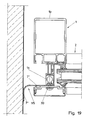
- a double-walled sealing part 93 is provided according to the exemplary embodiment in FIG. 13, which has two webs 7 '' each with a weather-side end bar 30 and a warm connection 71.
- the two bolts 2 present here can be pivoted about a common axis of rotation 72 in the plane of the drawing, there being a seal through the connection 71.
- the narrow areas are sealed both by the aforementioned seal 93 and by seals 7 according to the previous exemplary embodiments.
- the transition from an upper, vertical wall part to one located below it is wall section running to the left / down.
- Weather protection is provided here by a seal 94, which engages with end strips 30 according to the preceding exemplary embodiments in the end face of the narrow locking parts 2a and seals there. This also prevents moisture from penetrating in the direction of arrow 73.
- This connection is covered on the warm side by two cover strips 74, 75 which are rotatably hooked together (76).
- FIGS. 15 to 18 show a central post 1, which is constructed in principle in the same way as the bars described above, wherein two bars 2 are to be arranged in different angular positions both to the post 1 and to one another. This is done by pivoting the latch 2 around the point 77 in pivoting directions which lie in the plane of the drawing. Once the desired swivel position has been reached, it is fixed in place by a screw connection 78 indicated by a dot-dash line. Then a seal 93 is attached, which corresponds in structure to the seal 93 from FIG. 13. In connection with this, it can be seen from FIG. 15 that part 79 surrounds axis of rotation 77 and is connected to weather-side region 1a of the post.
- the parts 80 of the left hinge part and 81 of the right hinge part which are designed in the shape of a circular arc and surround the part 79, can be displaced relative to one another and part 79 can be slid relative to one another when the bolt 78 is pivoted accordingly, until after the desired angular position the screw connection 78 is reached through Parts 1a, 79 to 81 is screwed through.
- a hinge part 82 with the arcuate part 80 and another hinge part 83 with the arcuate part 81 are placed over the hinge base profile 79, as already stated.
- the screw connection 78 is carried out.
- the joint parts 82 and 83 are provided with webs 84, 85 which, in conjunction with elastic sealing profiles 86, close the joints to the cavity 87 of the post 1, ie seal them from the outside.
- the pressure strips 22b are screwed on as usual. They have a support surface 88 for fastening 89 of joint cover strips 74, 75, and a receiving groove 90 for fastening a clamp holder 90 '.
- the cover strips 57a are pushed into the clamp holder 90 until a cam 91 engages behind a groove edge 92.
- the fastenings 89 of the joint cover strips 74, 75 are thus covered.
- the circumferential seals 7, 93 and 94 can also be so produce that either from the factory or at the construction site extruded sealing parts (so-called "running yard goods") with corner pieces 96 (Fig. 13a, b) or 97 (Fig. 20, 20a) are connected by vulcanizing or gluing. These corner pieces fill the corners of the fields on mutually abutting transom and post parts and are provided with channels 37 and crossbars 38 already explained (see, for example, FIG. 10).
- the appropriately tailored strand-shaped seal is vulcanized together by pouring in the liquid mass of the shaped pieces 96 and 97.
- vulcanized mold corners and the "running yard goods" of the strand-shaped seal are delivered there from the factory, the strand-shaped sealing parts cut to the appropriate lengths being connected to the fittings by gluing.
- 13a, 13b shows the aforementioned variant of the invention in the case of parts at an angle to one another according to FIG. 13.
- Surface 98 lies against the post wall.
Landscapes
- Engineering & Computer Science (AREA)
- Civil Engineering (AREA)
- Structural Engineering (AREA)
- Architecture (AREA)
- Physics & Mathematics (AREA)
- Electromagnetism (AREA)
- Load-Bearing And Curtain Walls (AREA)
- Finishing Walls (AREA)
Applications Claiming Priority (2)
| Application Number | Priority Date | Filing Date | Title |
|---|---|---|---|
| DE4000769A DE4000769A1 (de) | 1990-01-12 | 1990-01-12 | Traggerippe fuer eine oder an einer fassadenwand |
| DE4000769 | 1990-01-12 |
Publications (3)
| Publication Number | Publication Date |
|---|---|
| EP0436868A2 true EP0436868A2 (fr) | 1991-07-17 |
| EP0436868A3 EP0436868A3 (en) | 1992-03-18 |
| EP0436868B1 EP0436868B1 (fr) | 1995-05-31 |
Family
ID=6397978
Family Applications (1)
| Application Number | Title | Priority Date | Filing Date |
|---|---|---|---|
| EP90124299A Expired - Lifetime EP0436868B1 (fr) | 1990-01-12 | 1990-12-15 | Structure porteuse pour une façade |
Country Status (3)
| Country | Link |
|---|---|
| EP (1) | EP0436868B1 (fr) |
| AT (1) | ATE123321T1 (fr) |
| DE (2) | DE4000769A1 (fr) |
Cited By (27)
| Publication number | Priority date | Publication date | Assignee | Title |
|---|---|---|---|---|
| GR1001541B (el) * | 1992-02-10 | 1994-04-29 | Christos Tsakiridis | Θερμομονωτικό σύστημα αλουμινίου. |
| EP0641902A1 (fr) * | 1993-08-26 | 1995-03-08 | METRA METALLURGICA TRAFILATI ALLUMINIO S.p.A. | Système d'assemblage de profilés pour réaliser des façades continus pour bâtiments civils ou similaires |
| FR2709780A1 (fr) * | 1993-09-06 | 1995-03-17 | Biguet Guy | Gamme d'armatures pour parois translucides et leur dispositif de fabrication. |
| EP0692586A1 (fr) * | 1994-07-16 | 1996-01-17 | Raico Bautechnik GmbH | Façade |
| GB2292955A (en) * | 1994-09-07 | 1996-03-13 | Don Reynolds Limited | Curtain walling |
| DE19519219A1 (de) * | 1995-05-24 | 1996-11-28 | Schneider Fensterfabrik Gmbh & | Holz-Aluminium-Pfosten-Riegelkonstruktion |
| NL1000698C2 (nl) * | 1995-06-29 | 1996-12-31 | Karel Jan Vollers | Bevestigingsinrichting voor het aan een gebouw bevestigen van gevel panelen, en gebouw voorzien van met die bevestigingsinrichting bevestig de gevelpanelen. |
| DE19525956A1 (de) * | 1995-07-17 | 1997-02-13 | Wicona Bausysteme Gmbh | Warmfassade |
| DE19525957A1 (de) * | 1995-07-17 | 1997-02-13 | Wicona Bausysteme Gmbh | Warmfassade |
| DE19613044A1 (de) * | 1996-04-01 | 1997-10-02 | Evg Bauprofil System Entwicklungs & Vermarktungsgesellschaft Mbh | Pfosten-Sprossen-Konstruktion |
| EP0799946A1 (fr) * | 1996-04-01 | 1997-10-08 | EVG Bauprofil-System Entwicklungs- und Vermarktungsgesellschaft mbH | Construction de poteaux et barres |
| EP1029998A1 (fr) * | 1999-02-16 | 2000-08-23 | Hoogovens Aluminium Profiltechnik GmbH | Dispositif pour la ventilation de l'espace entre panneaux de vitrage |
| EP1039059A2 (fr) * | 1999-03-25 | 2000-09-27 | Wishing Star Ltd | Elément de mur rideau |
| GB2349654A (en) * | 1999-05-07 | 2000-11-08 | Bowater Windows Ltd | Curtain wall with slidably engaging mullions and transoms |
| EP0971081A3 (fr) * | 1998-07-06 | 2001-02-07 | Hermann Gutmann Werke Gmbh | Façade de bâtiment ou façade de toit avec un cadre de poteaux et de traverses |
| FR2835012A1 (fr) * | 2002-01-24 | 2003-07-25 | Technal | Dispositif d'etancheite pour chassis de vitrage respirant |
| EP1338747A2 (fr) * | 2002-02-20 | 2003-08-27 | Norsk Hydro Asa | Joint d'étanchéité d'un cadre pour portes, fenêtres et similaires |
| WO2005121484A1 (fr) * | 2004-06-05 | 2005-12-22 | Neal Murray L | Systeme d'encadrement de fenetre |
| EP1643049A2 (fr) | 2004-10-04 | 2006-04-05 | Raico Bautechnik GmbH | Construction avec profilés porteurs |
| WO2007065963A1 (fr) * | 2005-08-08 | 2007-06-14 | Guillermo Rilova De La Hera | Mur rideau structurel modulaire d'ouverture exterieure |
| FR2942280A1 (fr) * | 2009-02-17 | 2010-08-20 | Profils Systemes | Assemblage de menuiserie |
| EP2322732A1 (fr) * | 2009-11-16 | 2011-05-18 | W.M.K.Secur S.r.l. | Façade ou paroi en verre dans une construction ignifuge |
| EP2444565A1 (fr) * | 2010-10-20 | 2012-04-25 | Bluesteel S.r.l. | Facade structurelle modulaire et kit pour assembler une facade structurelle modulaire |
| DE102011121275A1 (de) * | 2011-12-15 | 2013-06-20 | Rolf Kurz | Bausatz für Glaswände, insbesondere mit Brandschutzverglasung |
| US8844219B2 (en) | 2004-02-27 | 2014-09-30 | American Development Group International, Llc | Primary framing system and a method of installation |
| WO2015144720A1 (fr) * | 2014-03-26 | 2015-10-01 | Rehau Ag + Co | Profilé de fenêtre ou de porte en matière plastique |
| CN110965683A (zh) * | 2019-12-19 | 2020-04-07 | 北京凌云宏达幕墙工程有限公司 | 一种横竖龙骨连接角度任意调节的幕墙系统 |
Families Citing this family (8)
| Publication number | Priority date | Publication date | Assignee | Title |
|---|---|---|---|---|
| DE4143407A1 (de) * | 1991-12-05 | 1993-06-24 | Mannesmann Ag | Metallisches glashalteprofil |
| DE19803984C2 (de) * | 1998-02-02 | 2001-03-22 | Evg Bauprofil System Entwicklungs & Vermarktungsgesellschaft Mbh | Fassadenkonstruktion für polygonzugartigen Grundriß |
| DE10223038B4 (de) * | 2002-05-22 | 2004-09-16 | Akotherm Ne Metallhandelsgesellschaft Mbh | Fassadenkonstruktion mit einem durch ein Dichtelement abgedichteten riegelseitigen Isolierprofil |
| DE10319001B4 (de) * | 2003-04-25 | 2008-11-06 | Hermann Gutmann Werke Ag | Fassade oder Dach mit mehreren Entwässerungsebenen |
| DE102004058729B3 (de) * | 2004-12-06 | 2006-08-17 | Schindler Gmbh & Co. Fenster-Fassaden-Innenausbau Kg | Aufsatzkonstruktion für Holz/Pfosten-Riegelelemente |
| DE102005058286B4 (de) * | 2004-12-06 | 2009-04-09 | Schindler Gmbh & Co. Fenster-Fassaden-Innenausbau Kg | Aufsatzkonstruktion für Holz/Pfosten-Riegelelemente |
| US7779584B2 (en) | 2005-03-08 | 2010-08-24 | Muridal Inc. | Curtain wall system |
| DE102007053659A1 (de) * | 2007-11-08 | 2009-05-20 | Hermann Gutmann Werke Ag | Gebäudefassade in Brandschutzausführung |
Citations (4)
| Publication number | Priority date | Publication date | Assignee | Title |
|---|---|---|---|---|
| FR2455137A1 (fr) * | 1979-04-26 | 1980-11-21 | Hueck Fa E | Ossature, notamment pour elements rideaux formant des chassis de fenetres ou de portes, des facades, des murs de piscines couvertes et equivalents |
| FR2570770A1 (fr) * | 1984-09-26 | 1986-03-28 | Alcan Aluminium France | Procede d'assemblage et piece de liaison d'elements profiles transversaux, tels que des traverses et montants d'une structure d'encadrement |
| GB2172911A (en) * | 1985-03-30 | 1986-10-01 | James Alan Macey | Curtain walling |
| EP0399778A1 (fr) * | 1989-05-23 | 1990-11-28 | H.H. Robertson (U.K.) Limited | Mur rideau |
Family Cites Families (12)
| Publication number | Priority date | Publication date | Assignee | Title |
|---|---|---|---|---|
| DE1902702A1 (de) * | 1969-01-21 | 1970-09-17 | Glas Funck Kg | Profilleiste zum Befestigen von Scheiben in der Falz eines Profilrahmens |
| DE3317948C2 (de) * | 1983-05-17 | 1986-09-25 | GBK Gesellschaft für Baukonstruktionen mbH, 7250 Leonberg | Tragwerk für Glasfassaden, -wände und/oder -dächer |
| DE3406017A1 (de) * | 1984-02-20 | 1985-08-29 | Ritter Aluminium Gmbh, 7300 Esslingen | Dichtungsprofile fuer fassaden-, tuer- und fensterelemente |
| DE3419104A1 (de) * | 1984-05-23 | 1985-11-28 | Manfred 4972 Löhne Mühle | Stossverbindung fuer aus pfosten und riegeln zusammengesetzte fassaden- oder dachkonstruktionen |
| DE3539002A1 (de) * | 1985-11-02 | 1987-05-21 | Eltreva Ag | Fassadenwand |
| DE3540385A1 (de) * | 1985-11-14 | 1987-05-21 | Eltreva Ag | Fassadenkonstruktion aus metallprofilen |
| DE3603637C3 (de) * | 1986-02-06 | 2002-05-02 | Eural Firmengruppe Fuer Fenste | Fassadenkonstruktion, bei der horizontal vorgesehene Sprossen mit vertikal angeordneten, tragenden Pfosten verbunden sind |
| DE3633373A1 (de) * | 1986-10-01 | 1988-04-14 | Broekelmann Aluminium F W | Sparrenprofilanordnung fuer verglaste daecher von wintergaerten, veranden oder dergleichen |
| DE3639515A1 (de) * | 1986-11-20 | 1988-06-01 | Erbsloeh Julius & August | Auflageprofilstab fuer plattenartige bauelemente |
| DE3735016C1 (en) * | 1987-10-16 | 1988-10-06 | Wieland Werke Ag | Frame structure by the post/crossmember construction method, in particular for facades, roofs or the like |
| DE3741043C1 (en) * | 1987-12-04 | 1988-10-06 | Wieland Werke Ag | Frame structure of the post/crossmember construction type, in particular for facades, roofs, window walls or the like |
| DE3801186A1 (de) * | 1988-01-18 | 1989-07-27 | Schueco Int Gmbh & Co | Befestigung fuer isolierglasscheiben einer aussenwand- oder dachverglasung |
-
1990
- 1990-01-12 DE DE4000769A patent/DE4000769A1/de not_active Withdrawn
- 1990-12-15 AT AT90124299T patent/ATE123321T1/de not_active IP Right Cessation
- 1990-12-15 DE DE59009183T patent/DE59009183D1/de not_active Expired - Fee Related
- 1990-12-15 EP EP90124299A patent/EP0436868B1/fr not_active Expired - Lifetime
Patent Citations (4)
| Publication number | Priority date | Publication date | Assignee | Title |
|---|---|---|---|---|
| FR2455137A1 (fr) * | 1979-04-26 | 1980-11-21 | Hueck Fa E | Ossature, notamment pour elements rideaux formant des chassis de fenetres ou de portes, des facades, des murs de piscines couvertes et equivalents |
| FR2570770A1 (fr) * | 1984-09-26 | 1986-03-28 | Alcan Aluminium France | Procede d'assemblage et piece de liaison d'elements profiles transversaux, tels que des traverses et montants d'une structure d'encadrement |
| GB2172911A (en) * | 1985-03-30 | 1986-10-01 | James Alan Macey | Curtain walling |
| EP0399778A1 (fr) * | 1989-05-23 | 1990-11-28 | H.H. Robertson (U.K.) Limited | Mur rideau |
Cited By (42)
| Publication number | Priority date | Publication date | Assignee | Title |
|---|---|---|---|---|
| GR1001541B (el) * | 1992-02-10 | 1994-04-29 | Christos Tsakiridis | Θερμομονωτικό σύστημα αλουμινίου. |
| EP0641902A1 (fr) * | 1993-08-26 | 1995-03-08 | METRA METALLURGICA TRAFILATI ALLUMINIO S.p.A. | Système d'assemblage de profilés pour réaliser des façades continus pour bâtiments civils ou similaires |
| FR2709780A1 (fr) * | 1993-09-06 | 1995-03-17 | Biguet Guy | Gamme d'armatures pour parois translucides et leur dispositif de fabrication. |
| EP0692586A1 (fr) * | 1994-07-16 | 1996-01-17 | Raico Bautechnik GmbH | Façade |
| GB2292955B (en) * | 1994-09-07 | 1998-04-29 | Don Reynolds Limited | A curtain walling |
| GB2292955A (en) * | 1994-09-07 | 1996-03-13 | Don Reynolds Limited | Curtain walling |
| DE19519219C2 (de) * | 1995-05-24 | 1999-02-18 | Schneider Fensterfabrik Gmbh & | Holz-Aluminium-Pfosten-Riegelkonstruktion |
| DE19519219A1 (de) * | 1995-05-24 | 1996-11-28 | Schneider Fensterfabrik Gmbh & | Holz-Aluminium-Pfosten-Riegelkonstruktion |
| NL1000698C2 (nl) * | 1995-06-29 | 1996-12-31 | Karel Jan Vollers | Bevestigingsinrichting voor het aan een gebouw bevestigen van gevel panelen, en gebouw voorzien van met die bevestigingsinrichting bevestig de gevelpanelen. |
| US6041563A (en) * | 1995-06-29 | 2000-03-28 | Vollers; Karel Jan | Fixing device for fixing panels to a building, and building provided with panels fixed with said fixing device |
| WO1997001685A1 (fr) * | 1995-06-29 | 1997-01-16 | Karel Jan Vollers | Dispositif pour la fixation de panneaux a un immeuble, et immeuble pourvu de panneaux fixes a l'aide de ce dispositif de fixation |
| DE19525957C2 (de) * | 1995-07-17 | 2000-02-03 | Wicona Bausysteme Gmbh | Warmfassade |
| DE19525956C2 (de) * | 1995-07-17 | 1999-02-04 | Wicona Bausysteme Gmbh | Warmfassade |
| DE19525957A1 (de) * | 1995-07-17 | 1997-02-13 | Wicona Bausysteme Gmbh | Warmfassade |
| DE19525956A1 (de) * | 1995-07-17 | 1997-02-13 | Wicona Bausysteme Gmbh | Warmfassade |
| EP0799945A1 (fr) * | 1996-04-01 | 1997-10-08 | EVG Bauprofil-System Entwicklungs- und Vermarktungsgesellschaft mbH | Construction de poteaux et barres |
| EP0799946A1 (fr) * | 1996-04-01 | 1997-10-08 | EVG Bauprofil-System Entwicklungs- und Vermarktungsgesellschaft mbH | Construction de poteaux et barres |
| DE19613044A1 (de) * | 1996-04-01 | 1997-10-02 | Evg Bauprofil System Entwicklungs & Vermarktungsgesellschaft Mbh | Pfosten-Sprossen-Konstruktion |
| EP0971081A3 (fr) * | 1998-07-06 | 2001-02-07 | Hermann Gutmann Werke Gmbh | Façade de bâtiment ou façade de toit avec un cadre de poteaux et de traverses |
| EP1029998A1 (fr) * | 1999-02-16 | 2000-08-23 | Hoogovens Aluminium Profiltechnik GmbH | Dispositif pour la ventilation de l'espace entre panneaux de vitrage |
| EP1039059A3 (fr) * | 1999-03-25 | 2001-10-10 | Wishing Star Ltd | Elément de mur rideau |
| EP1039059A2 (fr) * | 1999-03-25 | 2000-09-27 | Wishing Star Ltd | Elément de mur rideau |
| GB2349654A (en) * | 1999-05-07 | 2000-11-08 | Bowater Windows Ltd | Curtain wall with slidably engaging mullions and transoms |
| GB2349654B (en) * | 1999-05-07 | 2003-11-12 | Bowater Windows Ltd | Curtain wall |
| FR2835012A1 (fr) * | 2002-01-24 | 2003-07-25 | Technal | Dispositif d'etancheite pour chassis de vitrage respirant |
| EP1338747A2 (fr) * | 2002-02-20 | 2003-08-27 | Norsk Hydro Asa | Joint d'étanchéité d'un cadre pour portes, fenêtres et similaires |
| EP1338747A3 (fr) * | 2002-02-20 | 2004-01-02 | Norsk Hydro Asa | Joint d'étanchéité d'un cadre pour portes, fenêtres et similaires |
| US8844219B2 (en) | 2004-02-27 | 2014-09-30 | American Development Group International, Llc | Primary framing system and a method of installation |
| US7533501B2 (en) | 2004-06-05 | 2009-05-19 | Guardian, Llc | Window framing system |
| US8112953B2 (en) | 2004-06-05 | 2012-02-14 | American Development Group International, Llc | Window framing system |
| WO2005121484A1 (fr) * | 2004-06-05 | 2005-12-22 | Neal Murray L | Systeme d'encadrement de fenetre |
| US8407953B2 (en) | 2004-06-05 | 2013-04-02 | American Development Group International, Llc | Window framing system |
| EP1643049A3 (fr) * | 2004-10-04 | 2007-08-01 | Raico Bautechnik GmbH | Construction avec profilés porteurs |
| EP1643049A2 (fr) | 2004-10-04 | 2006-04-05 | Raico Bautechnik GmbH | Construction avec profilés porteurs |
| WO2007065963A1 (fr) * | 2005-08-08 | 2007-06-14 | Guillermo Rilova De La Hera | Mur rideau structurel modulaire d'ouverture exterieure |
| FR2942280A1 (fr) * | 2009-02-17 | 2010-08-20 | Profils Systemes | Assemblage de menuiserie |
| EP2226442A1 (fr) * | 2009-02-17 | 2010-09-08 | Profils Systèmes | Assemblage de profilés, type emboîtement rigide |
| EP2322732A1 (fr) * | 2009-11-16 | 2011-05-18 | W.M.K.Secur S.r.l. | Façade ou paroi en verre dans une construction ignifuge |
| EP2444565A1 (fr) * | 2010-10-20 | 2012-04-25 | Bluesteel S.r.l. | Facade structurelle modulaire et kit pour assembler une facade structurelle modulaire |
| DE102011121275A1 (de) * | 2011-12-15 | 2013-06-20 | Rolf Kurz | Bausatz für Glaswände, insbesondere mit Brandschutzverglasung |
| WO2015144720A1 (fr) * | 2014-03-26 | 2015-10-01 | Rehau Ag + Co | Profilé de fenêtre ou de porte en matière plastique |
| CN110965683A (zh) * | 2019-12-19 | 2020-04-07 | 北京凌云宏达幕墙工程有限公司 | 一种横竖龙骨连接角度任意调节的幕墙系统 |
Also Published As
| Publication number | Publication date |
|---|---|
| EP0436868B1 (fr) | 1995-05-31 |
| ATE123321T1 (de) | 1995-06-15 |
| DE59009183D1 (de) | 1995-07-06 |
| EP0436868A3 (en) | 1992-03-18 |
| DE4000769A1 (de) | 1991-07-18 |
Similar Documents
| Publication | Publication Date | Title |
|---|---|---|
| EP0436868B1 (fr) | Structure porteuse pour une façade | |
| EP0436869B1 (fr) | Liaison au niveau du raccordement entre poteau et traverse d'une structure porteuse pour ou sur un mur de façade | |
| EP0100991A2 (fr) | Profil composé | |
| WO1990010124A1 (fr) | Ensemble pret a construire | |
| DE3040642C2 (de) | Fassadenwand | |
| DE3621408A1 (de) | Anschluss eines riegels an einen pfosten einer rahmen-konstruktion | |
| WO2006074973A1 (fr) | Façade modulaire pour batiments, joint de revetement en verre et vis | |
| EP0619403A1 (fr) | Construction d'un mur extérieur pour bâtiments ou pour toits inclinés | |
| DE2364395A1 (de) | Horizontal drehbares, doppelt verglastes fenster | |
| EP0221480B1 (fr) | Mur de façade | |
| DE19516464A1 (de) | Bausatz zur Halterung einer aus Platten, insbesondere Glasplatten oder dergleichen zusammensetzbaren Fassade oder Dacheindeckung | |
| DE2927463A1 (de) | Fassadenwand | |
| CH678347A5 (fr) | ||
| EP0730068B1 (fr) | Lucarne | |
| EP1174554A1 (fr) | Profile d'étanchéité pour une construction de poteaux et traverses | |
| DE19527141C2 (de) | Pfosten-Sprossen-Konstruktion, insbesondere für Fassaden | |
| EP1057961A2 (fr) | Seuil pour porte de maison ainsi que porte de maison | |
| WO2002053856A1 (fr) | Façade et/ou toit et barrette d'etancheite | |
| EP1329566A1 (fr) | Système de montants et traverses pour la construction de façades, toits etc | |
| DE2030746A1 (de) | Fensterrahmen aus Kunststoff mit einer Verstärkungseinlage, welche zugleich Zentralverschluß ist | |
| EP0247356B1 (fr) | Vitrage pour des serres, jardins d'hiver ou similaires et vitres utilisables pour cela | |
| AT506900B1 (de) | Fassadenplattentragkonstruktion | |
| EP0725202A1 (fr) | Armature pour portes ou fenêtres | |
| DE19854203C2 (de) | Pfosten/Riegel-Fassade für ein Gebäude | |
| DE19736860C2 (de) | Wärmegedämmte Fassade mit Fensterbändern |
Legal Events
| Date | Code | Title | Description |
|---|---|---|---|
| PUAI | Public reference made under article 153(3) epc to a published international application that has entered the european phase |
Free format text: ORIGINAL CODE: 0009012 |
|
| AK | Designated contracting states |
Kind code of ref document: A2 Designated state(s): AT BE CH DE DK ES FR GB IT LI LU NL SE |
|
| PUAL | Search report despatched |
Free format text: ORIGINAL CODE: 0009013 |
|
| AK | Designated contracting states |
Kind code of ref document: A3 Designated state(s): AT BE CH DE DK ES FR GB IT LI LU NL SE |
|
| 17P | Request for examination filed |
Effective date: 19920829 |
|
| 17Q | First examination report despatched |
Effective date: 19930715 |
|
| 17Q | First examination report despatched |
Effective date: 19940825 |
|
| GRAA | (expected) grant |
Free format text: ORIGINAL CODE: 0009210 |
|
| AK | Designated contracting states |
Kind code of ref document: B1 Designated state(s): AT BE CH DE DK ES FR GB IT LI LU NL SE |
|
| PG25 | Lapsed in a contracting state [announced via postgrant information from national office to epo] |
Ref country code: IT Free format text: LAPSE BECAUSE OF FAILURE TO SUBMIT A TRANSLATION OF THE DESCRIPTION OR TO PAY THE FEE WITHIN THE PRESCRIBED TIME-LIMIT;WARNING: LAPSES OF ITALIAN PATENTS WITH EFFECTIVE DATE BEFORE 2007 MAY HAVE OCCURRED AT ANY TIME BEFORE 2007. THE CORRECT EFFECTIVE DATE MAY BE DIFFERENT FROM THE ONE RECORDED. Effective date: 19950531 Ref country code: ES Free format text: THE PATENT HAS BEEN ANNULLED BY A DECISION OF A NATIONAL AUTHORITY Effective date: 19950531 Ref country code: DK Effective date: 19950531 |
|
| REF | Corresponds to: |
Ref document number: 123321 Country of ref document: AT Date of ref document: 19950615 Kind code of ref document: T |
|
| GBT | Gb: translation of ep patent filed (gb section 77(6)(a)/1977) |
Effective date: 19950605 |
|
| REF | Corresponds to: |
Ref document number: 59009183 Country of ref document: DE Date of ref document: 19950706 |
|
| ET | Fr: translation filed | ||
| PG25 | Lapsed in a contracting state [announced via postgrant information from national office to epo] |
Ref country code: SE Effective date: 19950831 |
|
| PG25 | Lapsed in a contracting state [announced via postgrant information from national office to epo] |
Ref country code: LU Free format text: LAPSE BECAUSE OF NON-PAYMENT OF DUE FEES Effective date: 19951231 |
|
| PLAV | Examination of admissibility of opposition |
Free format text: ORIGINAL CODE: EPIDOS OPEX |
|
| PLBQ | Unpublished change to opponent data |
Free format text: ORIGINAL CODE: EPIDOS OPPO |
|
| PLBI | Opposition filed |
Free format text: ORIGINAL CODE: 0009260 |
|
| PLAV | Examination of admissibility of opposition |
Free format text: ORIGINAL CODE: EPIDOS OPEX |
|
| PLBF | Reply of patent proprietor to notice(s) of opposition |
Free format text: ORIGINAL CODE: EPIDOS OBSO |
|
| 26 | Opposition filed |
Opponent name: SCHUECO INTERNATIONAL KG Effective date: 19960229 |
|
| NLR1 | Nl: opposition has been filed with the epo |
Opponent name: SCHUECO INTERNATIONAL KG |
|
| PLBF | Reply of patent proprietor to notice(s) of opposition |
Free format text: ORIGINAL CODE: EPIDOS OBSO |
|
| PLBF | Reply of patent proprietor to notice(s) of opposition |
Free format text: ORIGINAL CODE: EPIDOS OBSO |
|
| PLBO | Opposition rejected |
Free format text: ORIGINAL CODE: EPIDOS REJO |
|
| PLBN | Opposition rejected |
Free format text: ORIGINAL CODE: 0009273 |
|
| STAA | Information on the status of an ep patent application or granted ep patent |
Free format text: STATUS: OPPOSITION REJECTED |
|
| 27O | Opposition rejected |
Effective date: 19970516 |
|
| NLR2 | Nl: decision of opposition | ||
| PGFP | Annual fee paid to national office [announced via postgrant information from national office to epo] |
Ref country code: GB Payment date: 19991126 Year of fee payment: 10 |
|
| PGFP | Annual fee paid to national office [announced via postgrant information from national office to epo] |
Ref country code: FR Payment date: 19991217 Year of fee payment: 10 |
|
| PGFP | Annual fee paid to national office [announced via postgrant information from national office to epo] |
Ref country code: CH Payment date: 19991220 Year of fee payment: 10 Ref country code: AT Payment date: 19991220 Year of fee payment: 10 |
|
| PGFP | Annual fee paid to national office [announced via postgrant information from national office to epo] |
Ref country code: BE Payment date: 19991223 Year of fee payment: 10 Ref country code: NL Payment date: 19991223 Year of fee payment: 10 |
|
| PGFP | Annual fee paid to national office [announced via postgrant information from national office to epo] |
Ref country code: DE Payment date: 19991229 Year of fee payment: 10 |
|
| PG25 | Lapsed in a contracting state [announced via postgrant information from national office to epo] |
Ref country code: GB Free format text: LAPSE BECAUSE OF NON-PAYMENT OF DUE FEES Effective date: 20001215 Ref country code: AT Free format text: LAPSE BECAUSE OF NON-PAYMENT OF DUE FEES Effective date: 20001215 |
|
| PG25 | Lapsed in a contracting state [announced via postgrant information from national office to epo] |
Ref country code: LI Free format text: LAPSE BECAUSE OF NON-PAYMENT OF DUE FEES Effective date: 20001231 Ref country code: CH Free format text: LAPSE BECAUSE OF NON-PAYMENT OF DUE FEES Effective date: 20001231 Ref country code: BE Free format text: LAPSE BECAUSE OF NON-PAYMENT OF DUE FEES Effective date: 20001231 |
|
| BERE | Be: lapsed |
Owner name: REYNOLDS ALUMINIUM DEUTSCHLAND INTERNATIONALE VER Effective date: 20001231 |
|
| PG25 | Lapsed in a contracting state [announced via postgrant information from national office to epo] |
Ref country code: NL Free format text: LAPSE BECAUSE OF NON-PAYMENT OF DUE FEES Effective date: 20010701 |
|
| GBPC | Gb: european patent ceased through non-payment of renewal fee |
Effective date: 20001215 |
|
| REG | Reference to a national code |
Ref country code: CH Ref legal event code: PL |
|
| PG25 | Lapsed in a contracting state [announced via postgrant information from national office to epo] |
Ref country code: FR Free format text: LAPSE BECAUSE OF NON-PAYMENT OF DUE FEES Effective date: 20010831 |
|
| NLV4 | Nl: lapsed or anulled due to non-payment of the annual fee |
Effective date: 20010701 |
|
| REG | Reference to a national code |
Ref country code: FR Ref legal event code: ST |
|
| PG25 | Lapsed in a contracting state [announced via postgrant information from national office to epo] |
Ref country code: DE Free format text: LAPSE BECAUSE OF NON-PAYMENT OF DUE FEES Effective date: 20011002 |
|
| PLAB | Opposition data, opponent's data or that of the opponent's representative modified |
Free format text: ORIGINAL CODE: 0009299OPPO |