EP0432352B1 - Méthode et dispositif pour déterminer le temps entre départ et arrivée de concurrents ou semblables - Google Patents
Méthode et dispositif pour déterminer le temps entre départ et arrivée de concurrents ou semblables Download PDFInfo
- Publication number
- EP0432352B1 EP0432352B1 EP90110891A EP90110891A EP0432352B1 EP 0432352 B1 EP0432352 B1 EP 0432352B1 EP 90110891 A EP90110891 A EP 90110891A EP 90110891 A EP90110891 A EP 90110891A EP 0432352 B1 EP0432352 B1 EP 0432352B1
- Authority
- EP
- European Patent Office
- Prior art keywords
- time
- camera
- picture
- light barrier
- accurate
- Prior art date
- Legal status (The legal status is an assumption and is not a legal conclusion. Google has not performed a legal analysis and makes no representation as to the accuracy of the status listed.)
- Expired - Lifetime
Links
Images
Classifications
-
- G—PHYSICS
- G07—CHECKING-DEVICES
- G07C—TIME OR ATTENDANCE REGISTERS; REGISTERING OR INDICATING THE WORKING OF MACHINES; GENERATING RANDOM NUMBERS; VOTING OR LOTTERY APPARATUS; ARRANGEMENTS, SYSTEMS OR APPARATUS FOR CHECKING NOT PROVIDED FOR ELSEWHERE
- G07C1/00—Registering, indicating or recording the time of events or elapsed time, e.g. time-recorders for work people
- G07C1/22—Registering, indicating or recording the time of events or elapsed time, e.g. time-recorders for work people in connection with sports or games
- G07C1/24—Race time-recorders
-
- G—PHYSICS
- G04—HOROLOGY
- G04F—TIME-INTERVAL MEASURING
- G04F13/00—Apparatus for measuring unknown time intervals by means not provided for in groups G04F5/00 - G04F10/00
- G04F13/02—Apparatus for measuring unknown time intervals by means not provided for in groups G04F5/00 - G04F10/00 using optical means
Definitions
- the invention relates to a method for determining the time between the start and finish of competitors, vehicles or the like, in particular of runners, riders, racing cars or the like, wherein a recording camera with a playback device for still images and preferably with a monitor, a timer or time generator, which by the a start impulse, e.g. a starting pistol, start light barrier or the like triggered time during camera operation is faded into the individual images and indicates the respective time of the individual image from still image to still image, and wherein a light barrier or the like sensor is provided in accordance with a target line and the recording camera freezes still images provides a time interval of preferably two or four hundredths of a second and is set up in alignment with the finish line.
- a start impulse e.g. a starting pistol, start light barrier or the like triggered time during camera operation
- a light barrier or the like sensor is provided in accordance with a target line and the recording camera freezes still images provides a time interval of preferably two or four hundredths of a
- the invention further relates to a device for determining the time between start and finish using a Recording camera with playback device for still images and preferably with a monitor, a timer and a light barrier or the like sensor, in particular for carrying out the method.
- a method and a device of the type mentioned are known from DE-C 25 35 539. It is feared that the time that is shown may not exactly match the time of the creation of the image, because the individual image jumps could be offset in relation to the changes in the time information. It is therefore desirable in this previously known method that the start pulse coincides with the synchronization pulse of the camera so that the faded-in time and the time of the image formation correspond in each case. The aim is therefore that the start pulse also triggers the synchronization pulse for the camera. The further synchronization pulses of the camera for its individual images are then determined via the clock signal of the time generator.
- this known method cannot be carried out with a commercially available camera, since the camera must be able to be synchronized from the outside, that is to say externally.
- this camera is not only significantly more expensive, but also not for training purposes without a recorder can be used and cannot be exchanged at short notice in the event of failure.
- the object is therefore to create a method and a device of the type mentioned at the outset, with which precise timekeeping is possible with great certainty and yet with an inexpensive commercially available camera which does not have to be able to be synchronized externally.
- the solution to this apparently contradictory task is that the displayed time is measured and displayed at least one order of magnitude finer and more accurately than the smallest unit of time to be measured and that the output signal or the send pulse of the camera for an image signal controls the Zietgenerator in such a way that this in each case When a picture is taken, more precise time is displayed in this picture and recorded.
- the time generator is not used to control and synchronize the image sequence, but instead the output signal of the camera is used to indicate the time in the time generator when the image was created. Since this time is at least an order of magnitude finer and more precise than the time to be measured, it cannot happen that the faded-in time was created considerably "earlier" - in relation to the smallest unit of time to be measured - and thus "lags behind" the image display.
- the method according to the invention makes it possible to start the time generator with a start pulse, irrespective of whether the image formation starts exactly synchronously with the time generator or not, since the exact time that is valid for the image formation can be shown in the subsequent image sequence.
- An embodiment of the invention of considerable importance can consist in using the procedure according to DE-A-37 16 987. Thereafter, it is expedient that at least a second time is faded into the camera or still images with at least the accuracy of the time to be measured, which is synchronous with the first time, and that the fading in of this second time by interrupting the light barrier when the line of sight is touched
- the competitor, vehicle or the like is locked and the display of this finish time is at least recorded after a change of image - to a certain extent "frozen" - that is, at least in a next freeze frame, so that this image following the finish of a process that triggers the light barrier is separated by at least two images shows different time fades and shows the competitor, the vehicle or the like beyond the finish line, the difference between the two times being proportional to the distance traveled by the competitor. Vehicle or the like is beyond the finish line.
- a competitor's target time can remain frozen until the next possible light barrier touch, after which the current time appears again.
- this time is used as the official end time.
- the continuous time also recognizable in this still picture, should be used.
- This second time can thus be used to control and refine the entire measuring method and helps to determine the exact times of several competitors crossing the finish line in close order, who cannot all activate the light barrier in each case. It is expedient if the second time is likewise specified and faded in at least one order of magnitude more precisely or more precisely than the time to be measured, in particular for measurements to a hundredth of a second, to a thousandth of a second.
- Another advantage of this two-time overlay is that it can be constantly checked whether the light barrier is set correctly and whether the time-image synchronization is correct.
- the time difference between the two displayed times must be at least one hundredth of a second.
- the benchmark is always the time of the light barrier, since if the light barrier is set correctly, it determines the correct time between the start and target pulse, regardless of any time-image synchronization. If the specified times are an order of magnitude more precise than the most precise smallest measured variable of the time, i.e.
- a thousandth of a second are specified if measurements are to be made to the nearest hundredths of a second, it is ensured that the times displayed are of the order of magnitude of a time error to be feared due to image jumps Hundredths of a second not included because the elapsed time with the timing of the image recording practically matches to a thousandth of a second.
- the device according to the invention for solving the problem mentioned at the outset is that the time generator or the time measuring element and the time it fades into the camera image or still image is at least an order of magnitude more precise or more precise, in particular at least one digit after the decimal point, than that is measuring time and that the time generator is connected to the pulse generator for the outgoing image signal of the camera in such a way that at the moment of exposure the time in the time generator can be superimposed on the image and is recorded.
- the image signal from the camera ensures that the time generator enters the currently pending time into this image at the moment the image is created and displayed.
- time generator accurate to a thousandth of a second is provided for time measurements accurate to a hundredth of a second.
- time accuracies as are required today in numerous competitions, particularly in sprint running competitions, but also in other competitions aimed at speed.
- the device can have an expedient embodiment, which consists in the time generator being two independently specify times which run synchronously from one another, one of which is at least one order of magnitude more precise than the time to be measured and that one of the times, in particular by interrupting a light barrier coupled to the time generator and arranged in accordance with a target line, at the moment when the light barrier is interrupted fixable and can be faded into the next still picture in the following still picture in this fixed display, which differs from the running time.
- This makes it possible to continuously check and check whether the light barrier is set correctly and whether the time-image synchronization is working.
- the video signal or clock signal coming from the recording camera is led to a pulse separation, in particular via a signal amplifier, if the character generator used to record the time or times determined in the time generator is connected to the pulse separation and has a connecting line to a mixing stage , which in turn is connected to the camera by means of a line for transmitting the image signal, and if a video recorder and / or screen and / or video printer for displaying the image is connected to the times displayed at the mixing stage.
- the overall result is a relatively simply constructed device which is also inexpensive with regard to the inexpensive camera, with which nevertheless very exact target times can be determined without the camera having to be constantly synchronized from the outside and in particular by a time generator .
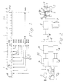
- a screen 1 of a monitor 2 shows the image recorded by a video camera 3 in a schematic representation.
- the finishing line 5 which at the same time corresponds to the installation of the light barrier 6 with light barrier switch 6a indicated in FIG. 2, and a runner or competitor 7 passing the finishing line 5.
- a field 11 with a Marking 11a can be seen where the time triggered by the light barrier 6 can be faded in and marked and marked as such.
- Another field 12 serves to display the continuously running time, as is supplied by the time generator 10 in a manner to be described. Two times can thus be indicated on the screen 1 and in a corresponding manner on the images of the video printer 9.
- Field 12 shows the running time triggered by a start pulse at a switch 13, which can be built into a start pistol, for example, during the operation of the camera 3, ie the individual images recorded by this camera 3 are those from the time generator 10 the time delivered at the time the image was taken is displayed.
- the emitting pulse from the camera 3 for an image signal first controls the time generator via a signal amplifier 14, a pulse separation 15 and a character generator 16 in such a way that the time pending at the time of an image recording in the time generator 10 in turn in this image is faded in and recorded via the character generator 16, a line 17 and via a mixing stage 18.
- the faded-in time is an order of magnitude finer or more precise than the smallest unit of time to be measured, ie in the exemplary embodiment in which an image pulse 19 of perhaps about a thousandth of a second is emitted every two hundredths of a second, and the target arrival times of the competitors 7 If you want to be accurate to hundredths of a second, times that are accurate to thousandths of a second are shown.
- Fig. 1 makes it clear that there are a total of twenty jumps, each of one thousandth of a second duration, available between two image pulses 19.
- the circuit shown in FIG. 2 thus ensures that the output pulse from the camera 3 also triggers the fading in of the time of the time generator 10, so that it is not necessary to synchronize the image pulses 19 from the time generator 10 and on to adjust this.
- the time given in this way by the time generator 10 when the image is created is displayed in the already mentioned field 12 of the screen 1 and at a corresponding point in a printed still image, since the camera 3 is also connected to the mixing stage 18 via the line 20.
- a second time is faded into the camera or still images at least with the accuracy of the time to be measured, but expediently also a time that is an order of magnitude more accurate or finer than the time to be measured, which is caused by the light barrier 6
- a competitor's touch on the target is triggered and, in particular, arrested and at least retained beyond a change of image, that is to say also faded into a subsequent still image.
- the image following the finish of a process which triggers the light barrier 6 thus contains two time insertions, which generally differ from one another, and the competitor 7 or else a vehicle or the like beyond the finish line 5.
- the difference between the two times is proportional to the distance covered by this competitor or the like has traveled beyond the finish line 5. In this way, there is a good possibility of checking whether the light barrier 6 is set correctly and the time-picture synchronization is OK.
- the time generator (clock) 10 is started via the switch 13, which can be installed in a starting pistol or can belong to a starting light barrier, for example.
- This time generator supplies the two times already mentioned, which run independently of one another, but synchronously. These two times are processed in the character generator 16 in the form of digits so that they can be superimposed and superimposed in the recorded image on the screen 1 or in the printer 9 and thus made visible. These two times therefore show corresponding values until the first light barrier pulse.
- the light barrier 6 in the area of the finish line 5 is interrupted by the runner 7 or another competitor, the light barrier or target time remains frozen with respect to its overlay in field 11, at least until the next possible still image or until the next possible light barrier touch, where then the respective new current time is made visible again.
- this time can be used as the official time.
- the continuously running time from field 12 should be used. With regard to this continuously running time that is faded into the individual images, the procedure according to the invention ensures that this time also corresponds exactly with the positioning of the rotor 7 on the respective image.
- the runner is in front of every two Hundredths of a second image jump closer to the finish line 5 than after the image jump, i.e. if the first image is closer to the finish line than the next still image is behind this finish line, the time difference between the two times must be at least one hundredth of a second .
- the standard measure is always the time triggered and faded in by the light barrier, since if the light barrier is set correctly, this represents the correct time between the start and target pulse, regardless of any time-image synchronization.
- the start pulse that starts the time generators 10 can be within this frequency without measuring errors of up to a hundredth of a second because the measurement accuracy of the time generator is at least one order of magnitude smaller or more precise than the actually required time measurement value, that is to say the time that has elapsed until the next picture is created.
- the elapsed time in each case coincides with the time of the image recording and is also superimposed or superimposed on the image during the image formation by means of the control already described. In detail, this happens as follows:
- the video signal clock signal or output signal which comes from the video camera 3, is led via the signal amplifier 14 to the pulse separation 15.
- the character generator 16 there is the time worked up for fade-in since triggering of the start pulse, which is now fed via the connecting line 17 to the mixing stage 18, as is the actual image signal 19 of the image reproduction via the line 20.
- the overall result is a device that specifies the respective target times practically to the nearest thousandth of a second regardless of an external synchronization of the camera and even a control option for the correct setting of the light barrier and also with respect to the time-image synchronization allowed.
- a recording or video camera 3 with playback device 8, 9 for still images and preferably with monitor 2, also a timer 10 or time generator that the by a start pulse, for example by a start pistol, start light barrier or the like, during the camera operation, the accompanying time is faded into the individual images supplied by the latter and indicates the respective time of the single image recording from still image to still image.
- a target light barrier 6 is arranged in accordance with the target line 5 and the recording camera delivers its still images at a fixed time interval of preferably two or four hundredths of a second and is also set up in alignment with the target line 5.
- the output signal of the camera 3 for an image signal to the video recorder 8 is used at the same time to control the time generator 10, so that it is caused to fade in the time that is present at the time of taking an image in this image that is being created at the time, whereby Taking into account a possible offset of the image formation at a point in time, for example, accurate to a hundredth of a second, the displayed time is at least one order of magnitude finer or more precise than the smallest unit of time to be measured, in the example mentioned it was measured from one unit of time to one hundredth of a second, that is to say measured in thousandths of a second and is displayed.
- Fig. 1 illustrates schematically and in table form the time lapse until the bid recording or creation 19, 19a, 19b etc., which in this embodiment takes two hundredths or twenty thousandths of a second. This scale therefore shows the clock frequency of the camera 3.
- the time scale AA also contained in FIG. 1 means the time lapse in the time generator. For example, at point B on this time scale, the start takes place with the time 0.000 seconds. This is followed by an image recording or an output signal from the camera for the first time at 19a. With this image signal (image creation), the time now pending in the time generator of 0.014 seconds is called up and recorded together with the image in the video recorder 8. After two hundredths of a second has elapsed, that is to say during image creation 19b, the second image is now created in an analogous manner. If the frequency of the camera 3 remains unchanged, there is now a pending time of 0.035 seconds for the image recording 19b.
- the frequency of the camera 3 can also deviate, shifts are possible both on one side and on the other side of the time scale, which is harmless, however, since the time which is present in the time generator and which is present at the time of the image formation (image signal) is always adopted . Even with such frequency deviations, it is thus ensured that the image appearing staggered after its creation contains exactly the time of its creation that has elapsed since the start.
- the shift in the scale AA compared to the time lapse of the image reproductions can also have a different value than the selected 0.014 seconds, which is indicated in FIG. 1 by the additional arrows Pf.
Landscapes
- Physics & Mathematics (AREA)
- General Physics & Mathematics (AREA)
- Measurement Of Unknown Time Intervals (AREA)
- Time Recorders, Dirve Recorders, Access Control (AREA)
- Closed-Circuit Television Systems (AREA)
- Camera Data Copying Or Recording (AREA)
- Waste-Gas Treatment And Other Accessory Devices For Furnaces (AREA)
- Feedback Control In General (AREA)
- Testing Electric Properties And Detecting Electric Faults (AREA)
Claims (8)
- Procédé pour déterminer le temps entre départ et arrivée de concurrents, véhicules ou analogues, en particulier de coureurs (7), cavaliers, voitures de course ou analogues, dans lequel sont prévus une caméra d'enregistrement (3) avec un appareil de reproduction (8) pour des images fixes (arrêts sur image) et, de préférence, un récepteur de contrôle (2), de même qu'un générateur de rythme ou horloge (10) qui incruste (affiche en incrustation) dans les différentes images le temps écoulé pendant le fonctionnement de la caméra, temps qui est déclenché par une impulsion de départ, fournie par exemple par un pistolet de starter, un barrage photoélectrique ou analogue, et qui indique d'une image fixe à l'autre l'instant de la prise d'image concernée, et dans lequel un barrage photoélectrique (6) ou un détecteur semblable est prévu en concordance avec une ligne d'arrivée (5) et la caméra d'enregistrement (3) délivre des images fixes avec un intervalle temporel fixe qui est de préférence de deux ou quatre centièmes de seconde et est installée en alignement avec la ligne d'arrivée (5), caractérisé en ce que le temps incrusté est mesuré et affiché avec une finesse ou précision supérieure d'au moins un facteur de dix à la plus petite unité de temps à mesurer, et que le signal de sortie (19) de la caméra (3) pilote l'horloge (10) de manière que le temps plus précis fourni par l'horloge à l'instant d'une prise d'image, soit incrusté dans l'image en question et enregistré.
- Procédé selon la revendication 1, caractérisé en ce que, pour mesurer des temps avec une précision d'un centième de seconde, des temps d'une précision d'un millième de seconde sont incrustés chaque fois dans l'image fixe.
- Procédé selon la revendication 1 ou 2, caractérisé en ce qu'au moins un second temps est incrusté au moins avec la précision du temps à mesurer dans les images défilantes de la caméra ou dans les images fixes, second temps qui s'écoule simultanément avec le premier temps, en synchronisme avec lui, et que l'incrustation de ce second temps est arrêtée par interruption du barrage photoélectrique (6) lorsqu'un concurrent (7), un véhicule ou analogue touche la ligne d'arrivée, et l'affichage de ce temps de passage par l'arrivée est retenu au moins au-delà d'un changement d'image, de sorte qu'il est également incrusté au moins dans une image fixe suivante, si bien que cette image, faisant suite à l'opération de déclenchement du barrage photoélectrique (6) correspondant au passage par l'arrivée, montre au moins deux incrustations de temps différents et le concurrent (7), le véhicule ou analogue au-delà de la ligne d'arrivée (5), la différence des deux temps étant proportionnelle au trajet couvert par le concurrent, le véhicule ou analogue au-delà de la ligne d'arrivée (5).
- Procédé selon la revendication 3, caractérisé en ce que le second temps est incrusté avec une finesse ou précision supérieure d'au moins un facteur de dix au temps à mesurer et à indiquer, en particulier, s'il s'agit de mesures avec une précision d'un centième de seconde, avec une précision d'un millième de seconde.
- Dispositif pour déterminer le temps entre départ et arrivée de concurrents (7), véhicules ou analogues à l'aide d'une caméra d'enregistrement (3) avec un appareil de reproduction (8, 9) pour fournir des images fixes (arrêts sur image) et, de préférence, un récepteur de contrôle (2), de même qu'un générateur de rythme ou horloge (10) et un barrage photoélectrique (6) ou un détecteur semblable, en particulier pour la mise en oeuvre du procédé selon une des revendications 1 à 4, caractérisé en ce que le générateur de rythme ou l'horloge (10) et le temps incrusté par lui dans l'image défilante de la caméra ou dans l'image fixe, possèdent une finesse ou une précision supérieure d'au moins un facteur de dix, en particulier une précision supérieure d'au moins une position derrière la virgule, au temps à mesurer, et que l'horloge (10) est connectée au générateur d'impulsions (15) pour le signal d'image sortant de la caméra (3), de manière qu'à l'instant d'une exposition, le temps fourni par l'horloge (10) puisse être incrusté dans l'image fixe.
- Dispositif selon la revendication 5, caractérisé en ce qu'une horloge (10) ayant une précision d'un millième de seconde est prévue pour des mesures de temps avec une précision d'un centième de seconde.
- Dispositif selon la revendication 5 ou 6, caractérisé en ce que l'horloge (10) indique au moins deux temps s'écoulant indépendamment l'un de l'autre, mais en synchronisme, dont l'un au moins est plus précis d'au moins un facteur de dix que le temps à mesurer, et que le comptage d'un des temps peut être arrêté, en particulier par interruption d'un barrage photoélectrique (6) couplé à l'horloge (10) et installé en concordance avec une ligne d'arrivée (5), à l'instant de l'interruption du barrage photoélectrique (6), ce temps arrêté étant incrustable dans l'image fixe suivante, dans laquelle il diffère de l'affichage du temps compté de façon continue.
- Dispositif selon une des revendications 5 à 7, caractérisé en ce que le signal vidéo ou le signal de rythme, venant de la caméra d'enregistrement ou de la caméra vidéo (3), est envoyé, en particulier à travers un amplificateur de signal (14), à un circuit séparateur d'impulsions (15), que le générateur de caractères (16), servant à l'enregistrement du temps ou des temps déterminés dans l'horloge (10), est connecté au circuit séparateur d'impulsions (15) et présente une ligne de liaison (17) avec un étage mélangeur (18), lui-même connecté par une ligne (20) à la caméra (3) pour la transmission du signal d'image, et qu'un magnétoscope (8) et/ou un écran (1) et/ou une imprimante vidéo (9) pour la visualisation de l'image avec le ou les temps incrusté(s) est ou sont connecté(s) à l'étage mélangeur (18).
Applications Claiming Priority (2)
| Application Number | Priority Date | Filing Date | Title |
|---|---|---|---|
| DE3937977 | 1989-11-15 | ||
| DE3937977A DE3937977C1 (fr) | 1989-11-15 | 1989-11-15 |
Publications (3)
| Publication Number | Publication Date |
|---|---|
| EP0432352A2 EP0432352A2 (fr) | 1991-06-19 |
| EP0432352A3 EP0432352A3 (en) | 1991-12-27 |
| EP0432352B1 true EP0432352B1 (fr) | 1994-12-07 |
Family
ID=6393577
Family Applications (1)
| Application Number | Title | Priority Date | Filing Date |
|---|---|---|---|
| EP90110891A Expired - Lifetime EP0432352B1 (fr) | 1989-11-15 | 1990-06-08 | Méthode et dispositif pour déterminer le temps entre départ et arrivée de concurrents ou semblables |
Country Status (5)
| Country | Link |
|---|---|
| US (1) | US5105395A (fr) |
| EP (1) | EP0432352B1 (fr) |
| JP (1) | JPH03171124A (fr) |
| AT (1) | ATE115314T1 (fr) |
| DE (2) | DE3937977C1 (fr) |
Families Citing this family (17)
| Publication number | Priority date | Publication date | Assignee | Title |
|---|---|---|---|---|
| CA2083170A1 (fr) * | 1991-04-02 | 1992-10-03 | Jean-Pierre Voillat | Systeme d'affichage instantane de la position d'un coureur dans une course a depart decale |
| JP3237124B2 (ja) * | 1991-04-19 | 2001-12-10 | ソニー株式会社 | 映像信号処理装置 |
| US5657077A (en) * | 1993-02-18 | 1997-08-12 | Deangelis; Douglas J. | Event recording system with digital line camera |
| US5552824A (en) * | 1993-02-18 | 1996-09-03 | Lynx System Developers, Inc. | Line object scene generation apparatus |
| JP2978357B2 (ja) * | 1993-03-22 | 1999-11-15 | 日立電子株式会社 | 計時システム |
| US6542183B1 (en) | 1995-06-28 | 2003-04-01 | Lynx Systems Developers, Inc. | Event recording apparatus |
| AU712182B2 (en) * | 1994-06-28 | 1999-10-28 | Lynx System Developers, Inc. | Event recording camera system |
| EP0898249B1 (fr) * | 1997-08-22 | 2003-05-02 | Omega Electronics S.A. | Système, notamment pour le chronométrage de courses; comportant un capteur photosensible et procédé de réglage de l'alignement d'un tel système sur une ligne de passage d'objets |
| US5831940A (en) * | 1997-08-27 | 1998-11-03 | Gillette; Warren | Solo electronic starter and timer system |
| US6545705B1 (en) | 1998-04-10 | 2003-04-08 | Lynx System Developers, Inc. | Camera with object recognition/data output |
| FR2835066A1 (fr) * | 2003-03-05 | 2003-07-25 | Alain Randazzo | Appareil de mesure permettant de chiffrer et de visualiser le nombre de secondes ecoulees entre un evenement precis choisi arbitrairement et l'instant present |
| DE10336447A1 (de) * | 2003-08-06 | 2005-03-10 | Gerd Hansen | Verfahren und Vorrichtung zum Erfassen und Verarbeiten von Daten eines Sportereignisses |
| US20050088524A1 (en) * | 2003-10-23 | 2005-04-28 | Delmar Bleckley | Lag meter |
| US20060146132A1 (en) * | 2005-01-05 | 2006-07-06 | Hy Mayerson | Video system having multiple video cameras for capturing events |
| CN101571964B (zh) * | 2008-12-04 | 2012-11-07 | 武汉理工大学 | 竞技比赛全自动图像计时及信息管理系统 |
| AU2011201119A1 (en) | 2010-03-18 | 2011-10-06 | Aristocrat Technologies Australia Pty Limited | A gaming system and a method of gaming |
| AT512991B1 (de) * | 2012-06-11 | 2015-06-15 | Airwin Entertainment Gmbh | System zur Durchführung von Rennen mit kleinen Tieren |
Family Cites Families (7)
| Publication number | Priority date | Publication date | Assignee | Title |
|---|---|---|---|---|
| US3678189A (en) * | 1969-12-11 | 1972-07-18 | Robert A Oswald | Method of producing time-position records of objects |
| US3714649A (en) * | 1970-05-18 | 1973-01-30 | Stewart Warner Corp | Vehicle race monitoring system |
| US3829869A (en) * | 1972-12-29 | 1974-08-13 | Specialty Instr Corp | Photo finish record system |
| CH629066B (fr) * | 1977-12-27 | Longines Montres Comp D | Installation de chronometrage avec prise de vue de television. | |
| DE3670940D1 (de) * | 1985-06-19 | 1990-06-07 | Yamaguchi Cinema Kk | Aufnahme- und wiedergabegeraet fuer videosignale. |
| US4643585A (en) * | 1986-03-26 | 1987-02-17 | Hillesland Gene G | Light-flash starting system |
| DE3716987C1 (de) * | 1987-05-21 | 1988-04-28 | Augustin Imhof | Verfahren und Vorrichtung zur Bestimmung der Zeit zwischen Start und Ziel von Wettkaempfern od.dgl. |
-
1989
- 1989-11-15 DE DE3937977A patent/DE3937977C1/de not_active Expired - Lifetime
-
1990
- 1990-06-08 AT AT90110891T patent/ATE115314T1/de not_active IP Right Cessation
- 1990-06-08 DE DE59007934T patent/DE59007934D1/de not_active Expired - Fee Related
- 1990-06-08 EP EP90110891A patent/EP0432352B1/fr not_active Expired - Lifetime
- 1990-11-15 JP JP2307318A patent/JPH03171124A/ja active Pending
- 1990-11-15 US US07/614,436 patent/US5105395A/en not_active Expired - Fee Related
Also Published As
| Publication number | Publication date |
|---|---|
| DE59007934D1 (de) | 1995-01-19 |
| DE3937977C1 (fr) | 1990-12-20 |
| ATE115314T1 (de) | 1994-12-15 |
| EP0432352A3 (en) | 1991-12-27 |
| JPH03171124A (ja) | 1991-07-24 |
| EP0432352A2 (fr) | 1991-06-19 |
| US5105395A (en) | 1992-04-14 |
Similar Documents
| Publication | Publication Date | Title |
|---|---|---|
| EP0432352B1 (fr) | Méthode et dispositif pour déterminer le temps entre départ et arrivée de concurrents ou semblables | |
| EP0291627B1 (fr) | Procédé et dispositif pour déterminer le temps entre le départ et l'arrivée des compétiteurs ou similaires | |
| DE2521110C3 (de) | Fahrtsimulator | |
| EP0252215B1 (fr) | Procédé de représentation simultanée d'au moins deux événements consécutifs en TV et dispositif de réalisation du procédé | |
| DE19626058C2 (de) | Elektronische Uhr | |
| DE3247810C2 (fr) | ||
| DE1449030A1 (de) | Zeitmessvorrichtung fuer Sportzwecke | |
| DE69721520T2 (de) | System mit einem Photosensor, insbesonder zur Zeitmessung bei Wettkämpfen, und Einstellverfahren zum Ausrichten eines solchen Systems auf eine Ziellinie | |
| DE4135385A1 (de) | Verfahren zur aufnahme von nacheinander erfolgenden aehnlichen bewegungsablaeufen mittels eines bildaufzeichnungsgeraetes | |
| DE3325810C2 (de) | Video-Einrichtung | |
| DE3132254C2 (de) | Anordnung zur Erfassung der Verzögerung von Geistersignalen in einem Fernsehsignal | |
| DE3248565A1 (de) | Zeitintervall-messeinrichtung | |
| DE2047653A1 (de) | Anlage zur Messung einer Zeitspanne, insbesondere zur Zeitmessung bei Sport wettkampfen | |
| EP0583441B1 (fr) | Dispositif pour mesurer des temps, notamment dans le domaine sportif | |
| DE1728240A1 (de) | Einrichtung zum Messen und Auswerten des Kegelfalls beim Kegelspiel | |
| DE4024499C1 (fr) | ||
| EP0384496A2 (fr) | Méthode et dispositif pour déterminer le temps entre départ et arrivée de concurrents ou semblables, ne déclenchant aucune barrière lumineuse | |
| DD154557A5 (de) | Einrichtung zur bestimmung, anzeige und/registrierung von wettbewerbsergebnissen | |
| DE19509600C1 (de) | Verfahren zur Synchronisation von Zeitintervallen | |
| DE2155600C3 (de) | Synchronisieranordnung für eine Fernsehabtasteinrichtung | |
| DE3217910A1 (de) | Plattenspieler zum abspielen einer eine information tragenden platte | |
| DE2633497A1 (de) | Vielfach-aufzeichnungsvorrichtung | |
| EP0380173B1 (fr) | Système pour la reproduction des signaux d'image à partir d'un support d'enregistrement en forme de ruban | |
| DE102022113894A1 (de) | Verfahren zur Zeitnahme im Sport | |
| DE2555044C2 (de) | Vorrichtung zur Erzeugung von Schichtaufnahmen |
Legal Events
| Date | Code | Title | Description |
|---|---|---|---|
| PUAI | Public reference made under article 153(3) epc to a published international application that has entered the european phase |
Free format text: ORIGINAL CODE: 0009012 |
|
| AK | Designated contracting states |
Kind code of ref document: A2 Designated state(s): AT CH DE FR GB IT LI |
|
| PUAL | Search report despatched |
Free format text: ORIGINAL CODE: 0009013 |
|
| AK | Designated contracting states |
Kind code of ref document: A3 Designated state(s): AT CH DE FR GB IT LI |
|
| 17P | Request for examination filed |
Effective date: 19920110 |
|
| 17Q | First examination report despatched |
Effective date: 19940330 |
|
| GRAA | (expected) grant |
Free format text: ORIGINAL CODE: 0009210 |
|
| AK | Designated contracting states |
Kind code of ref document: B1 Designated state(s): AT CH DE FR GB IT LI |
|
| PG25 | Lapsed in a contracting state [announced via postgrant information from national office to epo] |
Ref country code: IT Free format text: LAPSE BECAUSE OF FAILURE TO SUBMIT A TRANSLATION OF THE DESCRIPTION OR TO PAY THE FEE WITHIN THE PRE;WARNING: LAPSES OF ITALIAN PATENTS WITH EFFECTIVE DATE BEFORE 2007 MAY HAVE OCCURRED AT ANY TIME BEFORE 2007. THE CORRECT EFFECTIVE DATE MAY BE DIFFERENT FROM THE ONE RECORDED.SCRIBED TIME-LIMIT Effective date: 19941207 Ref country code: GB Effective date: 19941207 Ref country code: FR Effective date: 19941207 |
|
| REF | Corresponds to: |
Ref document number: 115314 Country of ref document: AT Date of ref document: 19941215 Kind code of ref document: T |
|
| REF | Corresponds to: |
Ref document number: 59007934 Country of ref document: DE Date of ref document: 19950119 |
|
| EN | Fr: translation not filed | ||
| GBV | Gb: ep patent (uk) treated as always having been void in accordance with gb section 77(7)/1977 [no translation filed] |
Effective date: 19941207 |
|
| PGFP | Annual fee paid to national office [announced via postgrant information from national office to epo] |
Ref country code: AT Payment date: 19950630 Year of fee payment: 6 Ref country code: CH Payment date: 19950630 Year of fee payment: 6 |
|
| PLBE | No opposition filed within time limit |
Free format text: ORIGINAL CODE: 0009261 |
|
| STAA | Information on the status of an ep patent application or granted ep patent |
Free format text: STATUS: NO OPPOSITION FILED WITHIN TIME LIMIT |
|
| 26N | No opposition filed | ||
| PG25 | Lapsed in a contracting state [announced via postgrant information from national office to epo] |
Ref country code: AT Effective date: 19960608 |
|
| PG25 | Lapsed in a contracting state [announced via postgrant information from national office to epo] |
Ref country code: CH Effective date: 19960630 Ref country code: LI Effective date: 19960630 |
|
| REG | Reference to a national code |
Ref country code: CH Ref legal event code: PL |
|
| PGFP | Annual fee paid to national office [announced via postgrant information from national office to epo] |
Ref country code: DE Payment date: 20000411 Year of fee payment: 10 |
|
| PG25 | Lapsed in a contracting state [announced via postgrant information from national office to epo] |
Ref country code: DE Free format text: LAPSE BECAUSE OF NON-PAYMENT OF DUE FEES Effective date: 20010403 |