EP0432352B1 - Method and device for determining the time between start and finish of athletes or suchlike - Google Patents
Method and device for determining the time between start and finish of athletes or suchlike Download PDFInfo
- Publication number
- EP0432352B1 EP0432352B1 EP90110891A EP90110891A EP0432352B1 EP 0432352 B1 EP0432352 B1 EP 0432352B1 EP 90110891 A EP90110891 A EP 90110891A EP 90110891 A EP90110891 A EP 90110891A EP 0432352 B1 EP0432352 B1 EP 0432352B1
- Authority
- EP
- European Patent Office
- Prior art keywords
- time
- camera
- picture
- light barrier
- accurate
- Prior art date
- Legal status (The legal status is an assumption and is not a legal conclusion. Google has not performed a legal analysis and makes no representation as to the accuracy of the status listed.)
- Expired - Lifetime
Links
Images
Classifications
-
- G—PHYSICS
- G07—CHECKING-DEVICES
- G07C—TIME OR ATTENDANCE REGISTERS; REGISTERING OR INDICATING THE WORKING OF MACHINES; GENERATING RANDOM NUMBERS; VOTING OR LOTTERY APPARATUS; ARRANGEMENTS, SYSTEMS OR APPARATUS FOR CHECKING NOT PROVIDED FOR ELSEWHERE
- G07C1/00—Registering, indicating or recording the time of events or elapsed time, e.g. time-recorders for work people
- G07C1/22—Registering, indicating or recording the time of events or elapsed time, e.g. time-recorders for work people in connection with sports or games
- G07C1/24—Race time-recorders
-
- G—PHYSICS
- G04—HOROLOGY
- G04F—TIME-INTERVAL MEASURING
- G04F13/00—Apparatus for measuring unknown time intervals by means not provided for in groups G04F5/00 - G04F10/00
- G04F13/02—Apparatus for measuring unknown time intervals by means not provided for in groups G04F5/00 - G04F10/00 using optical means
Definitions
- the invention relates to a method for determining the time between the start and finish of competitors, vehicles or the like, in particular of runners, riders, racing cars or the like, wherein a recording camera with a playback device for still images and preferably with a monitor, a timer or time generator, which by the a start impulse, e.g. a starting pistol, start light barrier or the like triggered time during camera operation is faded into the individual images and indicates the respective time of the individual image from still image to still image, and wherein a light barrier or the like sensor is provided in accordance with a target line and the recording camera freezes still images provides a time interval of preferably two or four hundredths of a second and is set up in alignment with the finish line.
- a start impulse e.g. a starting pistol, start light barrier or the like triggered time during camera operation
- a light barrier or the like sensor is provided in accordance with a target line and the recording camera freezes still images provides a time interval of preferably two or four hundredths of a
- the invention further relates to a device for determining the time between start and finish using a Recording camera with playback device for still images and preferably with a monitor, a timer and a light barrier or the like sensor, in particular for carrying out the method.
- a method and a device of the type mentioned are known from DE-C 25 35 539. It is feared that the time that is shown may not exactly match the time of the creation of the image, because the individual image jumps could be offset in relation to the changes in the time information. It is therefore desirable in this previously known method that the start pulse coincides with the synchronization pulse of the camera so that the faded-in time and the time of the image formation correspond in each case. The aim is therefore that the start pulse also triggers the synchronization pulse for the camera. The further synchronization pulses of the camera for its individual images are then determined via the clock signal of the time generator.
- this known method cannot be carried out with a commercially available camera, since the camera must be able to be synchronized from the outside, that is to say externally.
- this camera is not only significantly more expensive, but also not for training purposes without a recorder can be used and cannot be exchanged at short notice in the event of failure.
- the object is therefore to create a method and a device of the type mentioned at the outset, with which precise timekeeping is possible with great certainty and yet with an inexpensive commercially available camera which does not have to be able to be synchronized externally.
- the solution to this apparently contradictory task is that the displayed time is measured and displayed at least one order of magnitude finer and more accurately than the smallest unit of time to be measured and that the output signal or the send pulse of the camera for an image signal controls the Zietgenerator in such a way that this in each case When a picture is taken, more precise time is displayed in this picture and recorded.
- the time generator is not used to control and synchronize the image sequence, but instead the output signal of the camera is used to indicate the time in the time generator when the image was created. Since this time is at least an order of magnitude finer and more precise than the time to be measured, it cannot happen that the faded-in time was created considerably "earlier" - in relation to the smallest unit of time to be measured - and thus "lags behind" the image display.
- the method according to the invention makes it possible to start the time generator with a start pulse, irrespective of whether the image formation starts exactly synchronously with the time generator or not, since the exact time that is valid for the image formation can be shown in the subsequent image sequence.
- An embodiment of the invention of considerable importance can consist in using the procedure according to DE-A-37 16 987. Thereafter, it is expedient that at least a second time is faded into the camera or still images with at least the accuracy of the time to be measured, which is synchronous with the first time, and that the fading in of this second time by interrupting the light barrier when the line of sight is touched
- the competitor, vehicle or the like is locked and the display of this finish time is at least recorded after a change of image - to a certain extent "frozen" - that is, at least in a next freeze frame, so that this image following the finish of a process that triggers the light barrier is separated by at least two images shows different time fades and shows the competitor, the vehicle or the like beyond the finish line, the difference between the two times being proportional to the distance traveled by the competitor. Vehicle or the like is beyond the finish line.
- a competitor's target time can remain frozen until the next possible light barrier touch, after which the current time appears again.
- this time is used as the official end time.
- the continuous time also recognizable in this still picture, should be used.
- This second time can thus be used to control and refine the entire measuring method and helps to determine the exact times of several competitors crossing the finish line in close order, who cannot all activate the light barrier in each case. It is expedient if the second time is likewise specified and faded in at least one order of magnitude more precisely or more precisely than the time to be measured, in particular for measurements to a hundredth of a second, to a thousandth of a second.
- Another advantage of this two-time overlay is that it can be constantly checked whether the light barrier is set correctly and whether the time-image synchronization is correct.
- the time difference between the two displayed times must be at least one hundredth of a second.
- the benchmark is always the time of the light barrier, since if the light barrier is set correctly, it determines the correct time between the start and target pulse, regardless of any time-image synchronization. If the specified times are an order of magnitude more precise than the most precise smallest measured variable of the time, i.e.
- a thousandth of a second are specified if measurements are to be made to the nearest hundredths of a second, it is ensured that the times displayed are of the order of magnitude of a time error to be feared due to image jumps Hundredths of a second not included because the elapsed time with the timing of the image recording practically matches to a thousandth of a second.
- the device according to the invention for solving the problem mentioned at the outset is that the time generator or the time measuring element and the time it fades into the camera image or still image is at least an order of magnitude more precise or more precise, in particular at least one digit after the decimal point, than that is measuring time and that the time generator is connected to the pulse generator for the outgoing image signal of the camera in such a way that at the moment of exposure the time in the time generator can be superimposed on the image and is recorded.
- the image signal from the camera ensures that the time generator enters the currently pending time into this image at the moment the image is created and displayed.
- time generator accurate to a thousandth of a second is provided for time measurements accurate to a hundredth of a second.
- time accuracies as are required today in numerous competitions, particularly in sprint running competitions, but also in other competitions aimed at speed.
- the device can have an expedient embodiment, which consists in the time generator being two independently specify times which run synchronously from one another, one of which is at least one order of magnitude more precise than the time to be measured and that one of the times, in particular by interrupting a light barrier coupled to the time generator and arranged in accordance with a target line, at the moment when the light barrier is interrupted fixable and can be faded into the next still picture in the following still picture in this fixed display, which differs from the running time.
- This makes it possible to continuously check and check whether the light barrier is set correctly and whether the time-image synchronization is working.
- the video signal or clock signal coming from the recording camera is led to a pulse separation, in particular via a signal amplifier, if the character generator used to record the time or times determined in the time generator is connected to the pulse separation and has a connecting line to a mixing stage , which in turn is connected to the camera by means of a line for transmitting the image signal, and if a video recorder and / or screen and / or video printer for displaying the image is connected to the times displayed at the mixing stage.
- the overall result is a relatively simply constructed device which is also inexpensive with regard to the inexpensive camera, with which nevertheless very exact target times can be determined without the camera having to be constantly synchronized from the outside and in particular by a time generator .
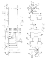
- a screen 1 of a monitor 2 shows the image recorded by a video camera 3 in a schematic representation.
- the finishing line 5 which at the same time corresponds to the installation of the light barrier 6 with light barrier switch 6a indicated in FIG. 2, and a runner or competitor 7 passing the finishing line 5.
- a field 11 with a Marking 11a can be seen where the time triggered by the light barrier 6 can be faded in and marked and marked as such.
- Another field 12 serves to display the continuously running time, as is supplied by the time generator 10 in a manner to be described. Two times can thus be indicated on the screen 1 and in a corresponding manner on the images of the video printer 9.
- Field 12 shows the running time triggered by a start pulse at a switch 13, which can be built into a start pistol, for example, during the operation of the camera 3, ie the individual images recorded by this camera 3 are those from the time generator 10 the time delivered at the time the image was taken is displayed.
- the emitting pulse from the camera 3 for an image signal first controls the time generator via a signal amplifier 14, a pulse separation 15 and a character generator 16 in such a way that the time pending at the time of an image recording in the time generator 10 in turn in this image is faded in and recorded via the character generator 16, a line 17 and via a mixing stage 18.
- the faded-in time is an order of magnitude finer or more precise than the smallest unit of time to be measured, ie in the exemplary embodiment in which an image pulse 19 of perhaps about a thousandth of a second is emitted every two hundredths of a second, and the target arrival times of the competitors 7 If you want to be accurate to hundredths of a second, times that are accurate to thousandths of a second are shown.
- Fig. 1 makes it clear that there are a total of twenty jumps, each of one thousandth of a second duration, available between two image pulses 19.
- the circuit shown in FIG. 2 thus ensures that the output pulse from the camera 3 also triggers the fading in of the time of the time generator 10, so that it is not necessary to synchronize the image pulses 19 from the time generator 10 and on to adjust this.
- the time given in this way by the time generator 10 when the image is created is displayed in the already mentioned field 12 of the screen 1 and at a corresponding point in a printed still image, since the camera 3 is also connected to the mixing stage 18 via the line 20.
- a second time is faded into the camera or still images at least with the accuracy of the time to be measured, but expediently also a time that is an order of magnitude more accurate or finer than the time to be measured, which is caused by the light barrier 6
- a competitor's touch on the target is triggered and, in particular, arrested and at least retained beyond a change of image, that is to say also faded into a subsequent still image.
- the image following the finish of a process which triggers the light barrier 6 thus contains two time insertions, which generally differ from one another, and the competitor 7 or else a vehicle or the like beyond the finish line 5.
- the difference between the two times is proportional to the distance covered by this competitor or the like has traveled beyond the finish line 5. In this way, there is a good possibility of checking whether the light barrier 6 is set correctly and the time-picture synchronization is OK.
- the time generator (clock) 10 is started via the switch 13, which can be installed in a starting pistol or can belong to a starting light barrier, for example.
- This time generator supplies the two times already mentioned, which run independently of one another, but synchronously. These two times are processed in the character generator 16 in the form of digits so that they can be superimposed and superimposed in the recorded image on the screen 1 or in the printer 9 and thus made visible. These two times therefore show corresponding values until the first light barrier pulse.
- the light barrier 6 in the area of the finish line 5 is interrupted by the runner 7 or another competitor, the light barrier or target time remains frozen with respect to its overlay in field 11, at least until the next possible still image or until the next possible light barrier touch, where then the respective new current time is made visible again.
- this time can be used as the official time.
- the continuously running time from field 12 should be used. With regard to this continuously running time that is faded into the individual images, the procedure according to the invention ensures that this time also corresponds exactly with the positioning of the rotor 7 on the respective image.
- the runner is in front of every two Hundredths of a second image jump closer to the finish line 5 than after the image jump, i.e. if the first image is closer to the finish line than the next still image is behind this finish line, the time difference between the two times must be at least one hundredth of a second .
- the standard measure is always the time triggered and faded in by the light barrier, since if the light barrier is set correctly, this represents the correct time between the start and target pulse, regardless of any time-image synchronization.
- the start pulse that starts the time generators 10 can be within this frequency without measuring errors of up to a hundredth of a second because the measurement accuracy of the time generator is at least one order of magnitude smaller or more precise than the actually required time measurement value, that is to say the time that has elapsed until the next picture is created.
- the elapsed time in each case coincides with the time of the image recording and is also superimposed or superimposed on the image during the image formation by means of the control already described. In detail, this happens as follows:
- the video signal clock signal or output signal which comes from the video camera 3, is led via the signal amplifier 14 to the pulse separation 15.
- the character generator 16 there is the time worked up for fade-in since triggering of the start pulse, which is now fed via the connecting line 17 to the mixing stage 18, as is the actual image signal 19 of the image reproduction via the line 20.
- the overall result is a device that specifies the respective target times practically to the nearest thousandth of a second regardless of an external synchronization of the camera and even a control option for the correct setting of the light barrier and also with respect to the time-image synchronization allowed.
- a recording or video camera 3 with playback device 8, 9 for still images and preferably with monitor 2, also a timer 10 or time generator that the by a start pulse, for example by a start pistol, start light barrier or the like, during the camera operation, the accompanying time is faded into the individual images supplied by the latter and indicates the respective time of the single image recording from still image to still image.
- a target light barrier 6 is arranged in accordance with the target line 5 and the recording camera delivers its still images at a fixed time interval of preferably two or four hundredths of a second and is also set up in alignment with the target line 5.
- the output signal of the camera 3 for an image signal to the video recorder 8 is used at the same time to control the time generator 10, so that it is caused to fade in the time that is present at the time of taking an image in this image that is being created at the time, whereby Taking into account a possible offset of the image formation at a point in time, for example, accurate to a hundredth of a second, the displayed time is at least one order of magnitude finer or more precise than the smallest unit of time to be measured, in the example mentioned it was measured from one unit of time to one hundredth of a second, that is to say measured in thousandths of a second and is displayed.
- Fig. 1 illustrates schematically and in table form the time lapse until the bid recording or creation 19, 19a, 19b etc., which in this embodiment takes two hundredths or twenty thousandths of a second. This scale therefore shows the clock frequency of the camera 3.
- the time scale AA also contained in FIG. 1 means the time lapse in the time generator. For example, at point B on this time scale, the start takes place with the time 0.000 seconds. This is followed by an image recording or an output signal from the camera for the first time at 19a. With this image signal (image creation), the time now pending in the time generator of 0.014 seconds is called up and recorded together with the image in the video recorder 8. After two hundredths of a second has elapsed, that is to say during image creation 19b, the second image is now created in an analogous manner. If the frequency of the camera 3 remains unchanged, there is now a pending time of 0.035 seconds for the image recording 19b.
- the frequency of the camera 3 can also deviate, shifts are possible both on one side and on the other side of the time scale, which is harmless, however, since the time which is present in the time generator and which is present at the time of the image formation (image signal) is always adopted . Even with such frequency deviations, it is thus ensured that the image appearing staggered after its creation contains exactly the time of its creation that has elapsed since the start.
- the shift in the scale AA compared to the time lapse of the image reproductions can also have a different value than the selected 0.014 seconds, which is indicated in FIG. 1 by the additional arrows Pf.
Abstract
Description
Die Erfindung betrifft ein Verfahren zur Bestimmung der Zeit zwischen Start und Ziel von Wettkämpfern, Fahrzeugen oder dergleichen, insbesondere von Wettläufern, Reitern, Rennautos oder dergleichen, wobei eine Aufzeichnungskamera mit Wiedergabegerät für Standbilder und vorzugsweise mit Monitor, ein Zeitgeber oder Zeitgenerator, der die durch einen Startimpuls, z.B. eine Startpistole, Startlichtschranke oder dergleichen ausgelöste mitlaufende Zeit während des Kamerabetriebes jeweils in die Einzelbilder einblendet und von Standbild zu Standbild die jeweilige Zeit der Einzelaufnahme angibt, und wobei eine Lichtschranke oder dergleichen Fühler in Übereinstimmung mit einer Ziellinie vorgesehen ist und die Aufzeichungskamera Standbilder in einem festen zeitlichen Abstand von vorzugsweise zwei oder vier hundertstel Sekunden liefert und in Flucht mit der Ziellinie aufgestellt wird.The invention relates to a method for determining the time between the start and finish of competitors, vehicles or the like, in particular of runners, riders, racing cars or the like, wherein a recording camera with a playback device for still images and preferably with a monitor, a timer or time generator, which by the a start impulse, e.g. a starting pistol, start light barrier or the like triggered time during camera operation is faded into the individual images and indicates the respective time of the individual image from still image to still image, and wherein a light barrier or the like sensor is provided in accordance with a target line and the recording camera freezes still images provides a time interval of preferably two or four hundredths of a second and is set up in alignment with the finish line.
Die Erfindung betrifft ferner eine Vorrichtung zur Bestimmung der Zeit zwischen Start und Ziel mit Hilfe einer Aufzeichnungskamera mit Wiedergabegerät für Standbilder und vorzugsweise mit Monitor, einem Zeitgeber und einer Lichtschranke oder dergleichen Fühler insbesondere zur Durchführung des Verfahrens.The invention further relates to a device for determining the time between start and finish using a Recording camera with playback device for still images and preferably with a monitor, a timer and a light barrier or the like sensor, in particular for carrying out the method.
Ein Verfahren und eine Vorrichtung der eingangs genannten Art sind aus der DE-C 25 35 539 bekannt. Dabei wird befürchtet, daß die jeweils eingeblendete Zeit möglicherweise nicht genau mit dem Zeitpunkt der Bildentstehung übereinstimmt, weil die einzelnen Bildsprünge gegenüber den Fortschaltungen der Zeitangaben versetzt sein könnten. Es ist deshalb bei diesem vorbekannten Verfahren angestrebt, daß der Startimpuls mit dem Synchronisationsimpuls der Kamera zusammentrifft, damit die eingeblendete Zeit und die Zeit der Bildentstehung jeweils übereinstimmen. Somit ist angestrebt, daß mit dem Startimpuls auch der Synchronisationsimpuls für die Kamera ausgelöst wird. Die weiteren Synchronisationsimpulse der Kamera für deren Einzelbilder werden danach über das Taktsignal des Zeitgenerators bestimmt.A method and a device of the type mentioned are known from DE-C 25 35 539. It is feared that the time that is shown may not exactly match the time of the creation of the image, because the individual image jumps could be offset in relation to the changes in the time information. It is therefore desirable in this previously known method that the start pulse coincides with the synchronization pulse of the camera so that the faded-in time and the time of the image formation correspond in each case. The aim is therefore that the start pulse also triggers the synchronization pulse for the camera. The further synchronization pulses of the camera for its individual images are then determined via the clock signal of the time generator.
Dies bedeutet, daß der Zeitgenerator auch die Bildfolge bestimmen soll, wobei jedoch der Benutzer keine Kontrolle darüber hat, ob dies - bei eventuellen Störungen - wirklich immer der Fall ist, also die von dem Zeitgenerator bei der Bildfolge im Hinblick auf den Startimpuls durchzuführende Korrektur beim Zieldurchgang der Wettkämpfer tatsächlich vollzogen ist. Eine genaue Übereinstimmung der eingeblendeten Zeit mit dem Zeitpunkt der jeweiligen Bildentstehung ist somit zwar angestrebt, aber nicht sichergestellt.This means that the time generator should also determine the image sequence, but the user has no control over whether this is really always the case - in the event of any faults, i.e. the correction to be carried out by the time generator in the image sequence with regard to the start pulse The competitors' finish line is actually completed. An exact match of the faded-in time with the point in time of the respective image creation is thus aimed at, but not ensured.
Darüber hinaus ist die Durchführung dieses vorbekannten Verfahrens mit einer handelsüblichen Kamera nicht möglich, da die Kamera ja von außen her, also extern synchronisiert werden können muß. Somit ist diese Kamera nicht nur wesentlich teurer, sondern ohne Recorder auch nicht für Trainingszwecke einsetzbar und bei Ausfall nicht kurzfristig austauschbar.In addition, this known method cannot be carried out with a commercially available camera, since the camera must be able to be synchronized from the outside, that is to say externally. Thus, this camera is not only significantly more expensive, but also not for training purposes without a recorder can be used and cannot be exchanged at short notice in the event of failure.
Es besteht deshalb die Aufgabe, ein Verfahren und eine Vorrichtung der eingangs erwähnten Art zu schaffen, womit eine präzise Zeitnahme mit großer Sicherheit und dennoch mit einer preiswerten handelsüblichen Kamera möglich ist, die nicht extern synchronisierbar sein muß.The object is therefore to create a method and a device of the type mentioned at the outset, with which precise timekeeping is possible with great certainty and yet with an inexpensive commercially available camera which does not have to be able to be synchronized externally.
Die Lösung dieser scheinbar widersprüchlichen Aufgabe besteht darin, daß die eingeblendete Zeit wenigstens eine Größenanordnung feiner und genauer als die kleinste zu messende Zeiteinheit gemessen und angezeigt wird und daß das Ausgangssignal beziehungsweise der Absendeimpuls der Kamera für ein Bildsignal den Zietgenerator derart ansteuert, daß dieser jeweils im Zeitpunkt einer Bildaufnahme dort anstehende genauere Zeit in dieses Bild eingeblendet und aufgezeichnet wird.The solution to this apparently contradictory task is that the displayed time is measured and displayed at least one order of magnitude finer and more accurately than the smallest unit of time to be measured and that the output signal or the send pulse of the camera for an image signal controls the Zietgenerator in such a way that this in each case When a picture is taken, more precise time is displayed in this picture and recorded.
Entgegen der bisherigen Lösung dient also nicht der Zeitgenerator zum Ansteuern und synchronisieren der Bildfolge, sondern umgekehrt wird das Ausgangssignal der Kamera dazu herangezogen, die im Augenblick der Bildentstehung im Zeitgenerator anstehende Zeit anzuzeigen. Da diese Zeit wenigstens eine Größenordnung feiner und genauer als die zu messende Zeit ist, kann nicht passieren, daß die eingeblendete Zeit schon erheblich "früher" - in Relation zu der kleinsten zu messenden Zeiteinheit - entstanden ist und also der Bildanzeige "hinterher hinkt".Contrary to the previous solution, the time generator is not used to control and synchronize the image sequence, but instead the output signal of the camera is used to indicate the time in the time generator when the image was created. Since this time is at least an order of magnitude finer and more precise than the time to be measured, it cannot happen that the faded-in time was created considerably "earlier" - in relation to the smallest unit of time to be measured - and thus "lags behind" the image display.
Zur Messung von Zeiten auf eine hunderststel Sekunde genau können beispielsweise auf tausendstel Sekunden genaue Zeiten in das jeweilige Standbild eingeblendet werden. Damit ist sichergestellt, daß zwischen den Sprüngen von hundertstel Sekunde zu hundertstel Sekunde die Zwischenzeiten angegeben und in auf eine tausendstel Sekunde genauer Übereinstimmung mit der Bildentstehung ist. Es ergibt sich auf diese Weise eine praktisch fehlerlose Zeitangabe jeweils zum einzelnen Standbild, da moderne Videokameras mit Belichtungszeiten ebenfalls in dieser Größenordnung also zum Beispiel von einer tausendstel Sekunde arbeiten können.To measure times accurate to a hundredth of a second, times that are accurate to a thousandth of a second can be superimposed on the respective still image. This ensures that the intermediate times are indicated between the jumps from hundredths of a second to hundredths of a second and that they correspond exactly to the formation of the image within a thousandth of a second. It results in this way a practically error-free time specification for each individual still image, since modern video cameras with exposure times can also work in this order of magnitude, for example, of a thousandth of a second.
Das erfindungsgemäße Verfahren ermöglicht es, den Zeitgenerator mit einem Startimpuls in Gang zu setzen unabhängig davon, ob die Bildentstehung genau synchron mit dem Zeitgenerator startet oder nicht, da in der anschließenden Bildfolge jeweils die exakte bei der Bildentstehung geltende Zeit eingeblendet werden kann.The method according to the invention makes it possible to start the time generator with a start pulse, irrespective of whether the image formation starts exactly synchronously with the time generator or not, since the exact time that is valid for the image formation can be shown in the subsequent image sequence.
Eine Ausgestaltung der Erfindung von erheblicher Bedeutung kann dabei darin bestehen, die Verfahrensweise gemäß DE-A-37 16 987 mitanzuwenden. Danach ist es zweckmäßig, daß in die Kamera- oder Standbilder mindestens eine zweite Zeit wenigstens mit der Genauigkeit der zu messenden Zeit eingeblendet wird, die gleichzeitig mit der ersten Zeit synchron abläuft, und daß die Einblendung dieser zweiten Zeit durch Unterbrechung der Lichtschranke bei Ziellinienberührung eines Wettkämpfers, Fahrzeuges oder dergleichen arretiert und die Anzeige dieser Zieldurchgangszeit zumindest über einen Bildwechsel hinaus festgehalten - gewissermaßen "eingefroren" -, also auch zumindest in einem nächstfolgenden Standbild eingeblendet wird, so daß dieses auf den Zieldurchgang eines die Lichtschranke auslösenden Vorgangs folgende Bild wenigstens zwei voneinander abweichende Zeiteinblendungen und den Wettkämpfer, das Fahrzeug oder dergleichen jenseits der Ziellinie zeigt, wobei die Differenz der beiden Zeiten proportional zu der Wegstrecke des Wettkämpfers. Fahrzeuges oder dergleichen über die Ziellinie hinaus ist. Diese Zielzeit eines Wettkämpfers kann zum Beispiel bis zur nächstmöglichen Lichtschrankenberührung eingefroren bleiben, wonach dann die jeweils wieder aktuelle Zeit erscheint.An embodiment of the invention of considerable importance can consist in using the procedure according to DE-A-37 16 987. Thereafter, it is expedient that at least a second time is faded into the camera or still images with at least the accuracy of the time to be measured, which is synchronous with the first time, and that the fading in of this second time by interrupting the light barrier when the line of sight is touched The competitor, vehicle or the like is locked and the display of this finish time is at least recorded after a change of image - to a certain extent "frozen" - that is, at least in a next freeze frame, so that this image following the finish of a process that triggers the light barrier is separated by at least two images shows different time fades and shows the competitor, the vehicle or the like beyond the finish line, the difference between the two times being proportional to the distance traveled by the competitor. Vehicle or the like is beyond the finish line. For example, a competitor's target time can remain frozen until the next possible light barrier touch, after which the current time appears again.
Nach der jeweiligen Position des Wettkämpfers an der Ziellinie kann nun entschieden oder überprüft werden, ob diese Zeit als die offizielle Endzeit herangezogen wird. Im Zweifelsfalle ist die durchlaufende, ebenfalls in diesem Standbild erkennbare Zeit heranzuziehen. Diese zweite Zeit kann also zur Kontrolle und Verfeinerung der gesamten Meßmethode dienen und hilft, die genauen Zeiten von mehreren in dichter Reihenfolge die Ziellinie überquerenden Wettkämpfern, die nicht alle jeweils die Lichtschranke aktivieren können, zu ermitteln. Dabei ist es zweckmäßig, wenn die zweite Zeit ebenfalls wenigstens eine Größenordnung feiner oder genauer als die zu messende Zeit, insbesondere bei Messungen auf Hundertstel Sekunden, auf Tausendstel Sekunden genau angegeben und eingeblendet wird.Depending on the position of the competitor at the finish line, it can now be decided or checked whether this time is used as the official end time. In case of doubt, the continuous time, also recognizable in this still picture, should be used. This second time can thus be used to control and refine the entire measuring method and helps to determine the exact times of several competitors crossing the finish line in close order, who cannot all activate the light barrier in each case. It is expedient if the second time is likewise specified and faded in at least one order of magnitude more precisely or more precisely than the time to be measured, in particular for measurements to a hundredth of a second, to a thousandth of a second.
Ein weiterer Vorteil dieser Einblendung zweier Zeiten besteht darin, daß ständig überprüft werden kann, ob die Lichtschranke richtig eingestellt ist und ob die Zeit-Bild-Synchronisation zutrifft.Another advantage of this two-time overlay is that it can be constantly checked whether the light barrier is set correctly and whether the time-image synchronization is correct.
Befindet sich beispielsweise ein Läufer am Ziel vor dem Bildsprung von zweihundertstel Sekunden näher an der Ziellinie als er sich nach dem Bildsprung hinter der Ziellinie befindet, muß die Zeitdifferenz der beiden eingeblendeten Zeiten mindestens eine hundertstel Sekunde betragen. Das Richtmaß ist hierbei immer die Lichtschrankenzeit, da diese bei richtiger Einstellung der Lichtschranke unabhängig von jeder Zeit-Bild-Synchronisation die korrekte Zeit zwischen Start- und Zielimpuls ermittelt. Wenn dabei die angegebenen Zeiten eine Größenordnung genauer als die genaueste kleinste Meßgröße der Zeit sind, also tausendstel Sekunden angegeben werden, wenn auf hundertstel Sekunden genau gemessen werden soll, ist sichergestellt, daß die eingeblendeten Zeiten den durch Bildsprünge sonst zu befürchtenden Zeitfehler in der Größenordnung einer hundertstel Sekunde nicht enthalten, da die jeweils abgelaufene Zeit mit dem Zietpunkt der Bildaufzeichnung praktisch auf eine tausendstel Sekunde genau übereinstimmt.For example, if a runner is closer to the finish line before the jump of two hundredths of a second than he is behind the finish line after the jump, the time difference between the two displayed times must be at least one hundredth of a second. The benchmark is always the time of the light barrier, since if the light barrier is set correctly, it determines the correct time between the start and target pulse, regardless of any time-image synchronization. If the specified times are an order of magnitude more precise than the most precise smallest measured variable of the time, i.e. a thousandth of a second are specified if measurements are to be made to the nearest hundredths of a second, it is ensured that the times displayed are of the order of magnitude of a time error to be feared due to image jumps Hundredths of a second not included because the elapsed time with the timing of the image recording practically matches to a thousandth of a second.
Die erfindungsgemäße Vorrichtung zur Lösung der eingangs genannten Aufgabe besteht darin, daß der Zeitgenerator oder das Zeitmeßglied und die von ihm in das Kamerabild oder Standbild eingeblendete Zeit wenigstens um eine Größenordnung feiner oder genauer, insbesondere um wenigstens eine Stelle hinter dem Komma genauer,als die zu messende Zeit ist und daß der Zeitgenerator mit dem Impulsgeber für das ausgehende Bildsignal der Kamera derart verbunden ist, daß im Augenblick einer Belichtung die im Zeitgenerator anstehende Zeit in das Bild einblendbar ist und aufgezeichnet wird. Somit ist es nicht erforderlich, die Kamera von außen her bzw. von dem Zeitgenerator her zu synchronisieren, sondern jeweils das Bildsignal der Kamera sorgt dafür, daß der Zeitgenerator im Augenblick der Bildentstehung und Darstellung die gerade anstehende Zeit in dieses Bild eingibt. Entsprechend exakt stimmen die in dem Bild wiedergegebene Position eines Wettkämpfers und die bis dahin abgelaufene Zeit überein, obwohl von Bildsprung zu Bildsprung zum Beispiel mindestens zweihundertstel Sekunden vergehen und bei nur auf hundertstel Sekunden genauer Zeiteinblendung, also Zeitfehler in der Größenordnung von etwa einer hundertstel Sekunde auftreten könnten.The device according to the invention for solving the problem mentioned at the outset is that the time generator or the time measuring element and the time it fades into the camera image or still image is at least an order of magnitude more precise or more precise, in particular at least one digit after the decimal point, than that is measuring time and that the time generator is connected to the pulse generator for the outgoing image signal of the camera in such a way that at the moment of exposure the time in the time generator can be superimposed on the image and is recorded. Thus, it is not necessary to synchronize the camera from the outside or from the time generator, but rather the image signal from the camera ensures that the time generator enters the currently pending time into this image at the moment the image is created and displayed. The position of a competitor represented in the picture and the time elapsed so far correspond correspondingly exactly, although at least two hundredths of a second pass from picture jump to picture jump and time fading occurs with an accuracy of only one hundredth of a second, i.e. time errors of the order of about one hundredth of a second could.
Zweckmäßig ist es dabei, wenn ein auf tausendstel Sekunden genauer Zeitgenerator für auf hundertstel Sekunden genaue Zeitmessungen vorgesehen ist. Dies sind Zeit-Genauigkeiten, wie sie heute bei zahlreichen Wettbewergen, insbesondere bei Sprint-Laufwettbewerben, aber auch in anderen auf Geschwindigkeit ausgerichteten Wettbewerben benötigt werden.It is expedient if a time generator accurate to a thousandth of a second is provided for time measurements accurate to a hundredth of a second. These are time accuracies, as are required today in numerous competitions, particularly in sprint running competitions, but also in other competitions aimed at speed.
Die Vorrichtung kann eine zweckmäßige Ausgestaltung aufweisen, die darin besteht, daß der Zeitgenerator zwei unabhängig voneinander, jedoch synchron ablaufende Zeiten angeben, deren eine um wenigstens eine Größenordnung genauer als die zu messende Zeit ist und daß eine der Zeiten, insbesondere durch Unterbrechung einer mit dem Zeitgenerator gekoppelten, in Übereinstimmung mit einer Ziellinie angeordneten Lichtschranke auf den Augenblick der Unterbrechung der Lichtschranke fixierbar und im folgenden Standbild in dieser fixierten, von der weiterlaufenden Zeit abweichenden Anzeige in das nächste Standbild einblendbar ist. Somit ist eine ständige Kontrolle und Überprüfung möglich, ob die Lichtschranke richtig eingestellt ist und die Zeit-Bild-Synchronisation funktioniert.The device can have an expedient embodiment, which consists in the time generator being two independently specify times which run synchronously from one another, one of which is at least one order of magnitude more precise than the time to be measured and that one of the times, in particular by interrupting a light barrier coupled to the time generator and arranged in accordance with a target line, at the moment when the light barrier is interrupted fixable and can be faded into the next still picture in the following still picture in this fixed display, which differs from the running time. This makes it possible to continuously check and check whether the light barrier is set correctly and whether the time-image synchronization is working.
Zweckmäßig ist es dabei, wenn das von der Aufnahmekamera kommende Videosignal oder Taktsignal insbesondere über einen Signalverstärker zu einer Impulstrennung geführt ist, wenn der zur Aufzeichnung der in dem Zeitgenerator ermittelten Zeit oder Zeiten dienende Zeichengenerator mit der Impulstrennung verbunden ist und eine Verbindungsleitung zu einer Mischstufe aufweist, die ihrerseits mittels einer Leitung zur Übermittlung des Bildsignales mit der Kamera verbunden ist, und wenn an die Mischstufe ein Videorecorder und/oder Bildschirm und/oder Videodrucker für die Darstellung des Bildes mit der/den eingeblendeten Zeiten verbunden ist. Es ergibt sich auf diese Weise insgesamt eine relativ einfach aufgebaute und auch im Hinblick auf die preiswerte Kamera insgesamt preiswerte Vorrichtung, mit der dennoch ganz exakte Zielzeiten ermittelt werden können, ohne daß die Kamera ständig von außen her und insbesondere von einem Zeitgenerator her synchronisiert werden muß.It is expedient if the video signal or clock signal coming from the recording camera is led to a pulse separation, in particular via a signal amplifier, if the character generator used to record the time or times determined in the time generator is connected to the pulse separation and has a connecting line to a mixing stage , which in turn is connected to the camera by means of a line for transmitting the image signal, and if a video recorder and / or screen and / or video printer for displaying the image is connected to the times displayed at the mixing stage. The overall result is a relatively simply constructed device which is also inexpensive with regard to the inexpensive camera, with which nevertheless very exact target times can be determined without the camera having to be constantly synchronized from the outside and in particular by a time generator .
Nachstehend ist ein Ausführungsbeispiel der Erfindung mit ihren ihr als wesentlich zugehörenden Einzelheiten anhand der Zeichnung noch näher beschrieben. Es zeigt:
- Fig. 1
- eine schematische Darstellung des zeitlichen Ablaufes der einzelnen Bildwiedergabe und ihrer zeitlichen Ausdehnung von etwa einer 1000stel Sekunde und einem Abstand von etwa zwei 100stel Sekunden sowie mit den zwischen ihnen angeordneten, im Abstand einer 1000stel Sekunde liegenden Wechsel der jeweils angegebenen Zeiten eines auf tausendstel Sekunden genauen Zeitgenerators und
- Fig. 2
- ein Blockschaltbild einer Vorrichtung zum Ermitteln von Zeiten zwischen Start und Ziel von Wettkämpfern mit einer Videokamera, Zeitgenerator, Bildschirm und Drucker.
- Fig. 1
- is a schematic representation of the temporal sequence of the individual image reproduction and their temporal expansion of about a 1000th of a second and a distance of about two 100ths of a second, and with the change between them, at intervals of a 1000th of a second, of the specified times of a time generator accurate to a thousandth of a second and
- Fig. 2
- a block diagram of a device for determining times between the start and finish of competitors with a video camera, time generator, screen and printer.
Ein Bildschirm 1 eines Monitors 2 zeigt das von einer Videokamera 3 aufgenommene Bild in schematisierter Darstellung.A
Dabei erkennt man die Markierungslinien 4 von Laufbahnen für einen Laufwettbewerb, die Ziellinie 5, die gleichzeitig der Aufstellung der in Fig. 2 links angedeuteten Lichtschranke 6 mit Lichtschranken-Schalter 6a entspricht, sowie einen die Ziellinie 5 passierenden Läufer oder Wettkämpfer 7.Here one can see the
Die Videokamera 3, die Lichtschranke 6 und der Monitor 2 gehören ebenso wie ein Videorecorder 8 und ein Videodrucker 9 mit einem Zietgenerator 10 zu einer Vorrichtung, mit welcher die Zeit zwischen Start und Ziel von Wettkämpfern, beispielsweise dem Läufer 7, aber auch von Fahrzeugen, Pferden oder dergleichen ermittelt und wiedergegeben werden können, wobei in noch zu beschreibender Weise Zeiten in das jeweils entstehende Bild, sei es am Drucker 9, sei es auf dem Bildschirm 1 eingeblendet werden können.The
In Fig. 2 ist auf dem Bildschirm 1 ein Feld 11 mit einer Markierung 11a erkennbar, wo die durch die Lichtschranke 6 jeweils ausgelöste Zeit eingeblendet und als solche markiert und gekennzeichnet werden kann. Ein weiteres Feld 12 dient zum Einblenden der ständig durchlaufenden Zeit, wie sie in noch zu beschreibender Weise von dem Zeitgenerator 10 geliefert wird. Es können also am Bildschirm 1 und in entsprechender Weise auf den Bildern des Videodruckers 9 zwei Zeiten angegeben werden. Feld 12 zeigt dabei die durch einen Startimpuls an einem Schalter 13, der zum Beispiel in eine Startpistole eingebaut sein kann, ausgelöste mitlaufende Zeit während des Betriebes der Kamera 3, d.h. in die von dieser Kamera 3 jeweils aufgenommenen Einzelbilder ist die von dem Zeitgenerator 10 jeweils zum Zeitpunkt der Bildaufnahme gelieferte Zeit eingeblendet. Dies wird dadurch erreicht, daß der von der Kamera 3 ausgehende Absendeimpuls für ein Bildsignal den Zeitgenerator zunächst über einen Signalverstärker 14, eine Impulstrennung 15 und einen Zeichengenerator 16 derart ansteuert, daß die jeweils im Zeitpunkte einer Bildaufnahme im Zeitgenerator 10 anstehende Zeit in dieses Bild wiederum über den Zeichengenerator 16,eine Leitung 17 und über eine Mischstufe 18 eingeblendet und aufgezeichnet wird. Gemaß Fig. 1 ist dabei die eingeblendete Zeit eine Größenordnung feiner oder genauer als die kleinste zu messende Zeiteinheit, d.h. im Ausführungsbeispiel, in welchem alle zwei hundertstel Sekunden ein Bildimpuls 19 von vielleicht etwa einer tausendstel Sekunde Dauer abgegeben wird, und die Zieleingangszeiten der Wettkämper 7 auf hundertstel Sekunden genau sein sollen, werden auf tausendstel Sekunden genaue Zeiten eingeblendet. Fig. 1 macht deutlich, daß also zwischen zwei Bildimpulsen 19 insgesamt zwanzig Sprünge von jeweils einer tausendstel Sekunde Dauer zur Verfügung stehen. Somit kann nicht nur die exakt zwischen zwei Bildsprüngen um eine hundertstel Sekunde weitergegangene Zeit angegeben werden, sondern falls die Bildentstehung gegenüber der durch den Startimpuls ausgelösten Zeitfolge verschoben ist, wird jeweils auf eine tausendstel Sekunde genau die Zeit in das Bild eingeblendet, zu der es im Abstand zum Startimpuls entsteht. Diese Abfrage erfolgt auch mit jedem weiteren Bildsignal, da die Frequenz der Kamera nicht unbedingt mit der des Zeitgenerators übereinstimmt und es so zu Zeitverschiebungen innerhalb der Abfragezeiten kommen kann, die mit der am Start ermittelten, nicht identisch sein muß.In Fig. 2 on the
Durch die in Fig. 2 erkennbare Schaltung wird also dafür gesorgt, daß der Ausgangsimpuls der Kamera 3 auch die Einblendung der jeweils anstehenden Zeit des Zeitgenerators 10 auslöst, so daß also nicht erforderlich ist, die Bildimpulse 19 von dem Zeitgenerator 10 aus zu synchronisieren und an diesen anzupassen.The circuit shown in FIG. 2 thus ensures that the output pulse from the
Die auf diese Weise zeitgleich vom Zeitgenerator 10 mit der Bildentstehung abgegebene Zeit wird in dem schon erwähnten Feld 12 des Bildschirmes 1 und an einer entsprechenden Stelle eines ausgedruckten Standbildes angezeigt, da die Kamera 3 über die Leitung 20 ebenfalls mit der Mischstufe 18 verbunden ist.The time given in this way by the time generator 10 when the image is created is displayed in the already mentioned field 12 of the
Im Ausführungsbeispiel ist nun vorgesehen, daß in die Kamera- oder Standbilder eine zweite Zeit wenigstens mit der Genauigkeit der zu messenden Zeit, zweckmäßigerweise aber ebenfalls eine um eine Größenordnung genauere oder feinere Zeit als die zu messende Zeit eingeblendet wird, die durch die Lichtschranke 6 bei Zielberührung eines Wettkämpfers ausgelöst und insbesondere arretiert und zumindest über einen Bildwechsel hinaus festgehalten, also auch in ein nächstfolgendes Standbild eingeblendet wird. Das auf den Zieldurchgang eines die Lichtschranke 6 auslösenden Vorganges folgende Bild enthält also zwei in der Regel voneinander abweichende Zeiteinblendungen und den Wettkämpfer 7 oder auch ein Fahrzeug oder dergleichen jenseits der Ziellinie 5. Die Differenz der beiden Zeiten ist proportional zu der Wegstrecke, die dieser Wettkämper oder dergleichen über die Ziellinie 5 hinaus zurückgelegt hat. Auf diese Weise ergibt sich eine gute Kontrollmöglichkeit dafür, ob die Lichtschranke 6 richtig eingestellt ist und die Zeit-Bild-Synchronisation in Ordnung ist.In the exemplary embodiment it is now provided that a second time is faded into the camera or still images at least with the accuracy of the time to be measured, but expediently also a time that is an order of magnitude more accurate or finer than the time to be measured, which is caused by the light barrier 6 A competitor's touch on the target is triggered and, in particular, arrested and at least retained beyond a change of image, that is to say also faded into a subsequent still image. The image following the finish of a process which triggers the light barrier 6 thus contains two time insertions, which generally differ from one another, and the
Mit Hilfe der vorstehend beschriebenen Vorrichtung und dem ebenfalls beschriebenen Verfahren ist folgender Meßverlauf durchführbar:With the aid of the device described above and the method also described, the following measurement process can be carried out:
Über den Schalter 13, der beispielsweise in einer Startpistole eingebaut oder zu einer Start-Lichtschranke gehören kann, wird der Zeitgenerator (Uhr) 10 in Gang gesetzt. Dieser Zeitgenerator liefert die bereits erwähnten zwei Zeiten, die zwar unabhängig voneinander, jedoch synchron ablaufen. Diese beiden Zeiten werden in dem Zeichengenerator 16 in Form von Ziffern so aufgearbeitet, daß sie in dem aufgezeichneten Bild auf dem Bildschirm 1 oder auch im Drucker 9 überlagert und eingeblendet werden können und so sichtbar gemacht werden. Diese beiden Zeiten zeigen also bis zum ersten Lichtschrankenimpuls übereinstimmende Werte.The time generator (clock) 10 is started via the switch 13, which can be installed in a starting pistol or can belong to a starting light barrier, for example. This time generator supplies the two times already mentioned, which run independently of one another, but synchronously. These two times are processed in the character generator 16 in the form of digits so that they can be superimposed and superimposed in the recorded image on the
Wird die Lichtschranke 6 im Bereich der Ziellinie 5 durch den Läufer 7 oder einen sonstigen Wettkämpfer unterbrochen, bleibt die Lichtschranken- oder Zielzeit bezüglich ihrer Einblendung in Feld 11 eingefroren stehen und zwar zumindest bis zum nächstmöglichen Standbild oder bis zur nächstmöglichen Lichtschrankenberührung, wo dann die jeweils neue aktuelle Zeit wieder sichtbar gemacht wird. Nach Überprüfung der Position des Läufers 7 im Bereich der Ziellinie 5 kann entschieden werden, ob diese Zeit als offizielle Zeit herangezogen werden kann. Im Zweifelsfalle ist die ständig weiter durchlaufende Zeit aus Feld 12 heranzuziehen. Bezüglich dieser ständig weiterlaufenden, in die Einzelbilder eingeblendeten Zeit ist durch die erfindungsgemäße Verfahrensweise sichergestellt, daß diese Zeit auch mit der Positionierung des Läufers 7 auf dem jeweiligen Bild genau übereinstimmt.If the light barrier 6 in the area of the
Befindet sich der Läufer beispielsweise vor dem alle zwei hundertstel Sekunden erfolgenden Bildsprung näher an der Ziellinie 5, als nach dem Bildsprung, d.h. befindet er sich bei einem ersten zielnahen Bild näher vor der Ziellinie als er bei dem nächsten Standbild hinter dieser Ziellinie ist, muß die Zeitdifferenz der beiden Zeiten mindestens eine hundertstel Sekunde betragen. Das Richtmaß ist dabei immer die durch die Lichtschranke ausgelöste und eingeblendete Zeit, da diese bei richtiger Einstellung der Lichtschranke unabhängig von jeder Zeit-Bild-Synchronisation die korrekte Zeit zwischen Start- und Zielimpuls darstellt.For example, the runner is in front of every two Hundredths of a second image jump closer to the
Da eine handelsübliche Videokamera 3, nicht aber eine teuere, extern synchronisierbare Kamera Verwendung finden können soll und diese über ein eigenes Taktsystem verfügt, kann der Startimpuls, der die Zeitgeneratoren 10 startet, innerhalb dieser Frequenz liegen, ohne zu Meßfehlern von bis zu einer hundertstel Sekunde zu führen, da die Meßgenauigkeit des Zeitgenerators um wenigstens eine Größenordnung kleiner bzw. genauer als der eigentlich geforderte Zeit-Meßwert ist, also auch die Zeit ermittelt werden kann, die bis zur Erstellung des jeweils nächsten Bildes abgelaufen ist. Dies bedeutet, daß die jeweils abgelaufene Zeit mit dem Zeitpunkt der Bild-Aufzeichnung übereinstimmt und über die schon beschriebene Ansteuerung auch genau während dieser Bildentstehung in das Bild überlagert oder eingeblendet wird. Im einzelnen geschieht dies folgendermaßen:Since a commercially
Das Videosignal-Taktsignal oder Ausgangssignal, welches von der Videokamera 3 kommt, wird über den Signalverstärker 14 zur Impulstrennung 15 geführt. Im Zeichengenerator 16 liegt die zur Einblendung aufgearbeitete Zeit seit Auslösung des Startimpulses vor, die nun über die Verbindungsleitung 17 der Mischstufe 18 ebenso zugeführt wird, wie das eigentliche Bildsignal 19 der Bildwiedergabe über die Leitung 20. Diese beiden Informationen, die somit aus der Mischstufe 18 kommen, werden im Videorecorder 8 auf Magnetband aufgezeichnet und können beispielsweise nach Ablauf des Geschehens auf dem Bildschirm 1 und dem Videodrucker 9 zum Zwecke der Auswertung und Dokumentation reproduziert werden. Trotz der Verwendungsmöglichkeit sehr preiswerter Bausteine ergibt sich also insgesamt eine Vorrichtung, die die jeweiligen Zielzeiten unabhängig von einer externen Synchronisation der Kamera praktisch auf tausendstel Sekunden genau angibt und sogar noch eine Kontrollmöglichkeit für die richtige Einstellung der Lichtschranke und auch bezüglich der Zeit-Bild-Synchronisation erlaubt.The video signal clock signal or output signal, which comes from the
Zur Bestimmung der Zeit zwischen Start und Ziel von Wettkämpfern oder Wettläufern 7, Reitern, Rennautos, Fahrzeugen oder dergleichen ist eine Aufzeichnungs- oder Videokamera 3 mit Wiedergabegerät 8, 9 für Standbilder und vorzugsweise mit Monitor 2, ferner ein Zeitgeber 10 oder Zeitgenerator, der die durch einen Startimpuls, zum Beispiel durch eine Startpistole, Startlichtschranke oder dergleichen ausgelöste mitlaufende Zeit während des Kamerabetriebes jeweils in die von dieser gelieferten Einzelbilder einblendet und von Standbild zu Standbild die jeweilige Zeit der Einzelbildaufnahme angibt, vorgesehen. Ferner ist dabei eine Ziel-Lichtschranke 6 in Übereinstimmung mit der Ziellinie 5 angeordnet und die Aufzeichnungskamera liefert ihre Standbilder in einem festen zeitlichen Abstand von vorzugsweise zwei oder vier hundertstel Sekunden und ist ebenfalls in Flucht mit der Ziellinie 5 aufgestellt. Dabei wird das Ausgangssignal der Kamera 3 für ein Bildsignal an den Videorecorder 8 gleichzeitig dazu verwendet, den Zeitgenerator 10 anzusteuern, so daß dieser veranlaßt wird, die jeweils im Zeitpunkt einer Bildaufnahme in ihm anstehende Zeit in dieses in diesem Augenblick entstehende Bild einzublenden, wobei zur Berücksichtigung eines eventuellen Versatzes der Bildentstehung zu einem zum Beispiel auf hundertstel Sekunden genauen Zeitpunkt die eingeblendete Zeit wenigstens eine Größenordnung feiner oder genauer als die kleinste zu messende Zeiteinheit, bei dem genannten Beispiel von einer zu messenden Zeiteinheit auf hundertstel Sekunden genau also intausendstel Sekunden gemessen und angezeigt wird.
Fig. 1 verdeutlicht schematisch und in Tabellenform den Zeitablauf bis zu der Bidlaufzeichnung oder -entstehung 19, 19a, 19b usw., der in diesem Ausführungsbeispiel je zwei hundertstel oder zwanzig tausendstel Sekunden dauert. Diese Skala zeigt also die Taktfrequenz der Kamera 3.To determine the time between the start and finish of competitors or
Fig. 1 illustrates schematically and in table form the time lapse until the bid recording or
Die auch in Fig. 1 enthaltene Zeitskala A-A bedeutet dabei den Zeitablauf im Zeitgenerator. Beispielsweise erfolgt an der Stelle B dieser Zeitskala der Start mit der Zeit 0,000 Sekunden. Danach erfolgt zum ersten Mal bei 19a eine Bildaufzeichnung oder ein Ausgangssignal der Kamera. Mit diesem Bildsignal (Bilderstellung) wird die im Zeitgenerator inzwischen anstehende Zeit von 0,014 Sekunden abgerufen und gemeinsam mit dem Bild im Videorecorder 8 zur Aufzeichnung gebracht. Nach Ablauf von zwei hundertstel Sekunden, also bei der Bilderstellung 19b, wird nun in analoger Weise das zweite Bild erstellt. Falls die Frequenz der Kamera 3 unverändert bleibt, ergibt sich bei der Bildaufzeichnung 19b nun eine anstehende Zeit von 0,035 Sekunden.
Da die Frequenz der Kamera 3 aber auch abweichen kann, sind Verschiebungen sowohl nach der einen als auch der anderen Seite der Zeitskala möglich, was jedoch unschädlich ist, da stets die im Zeitgenerator anstehende Zeit übernommen wird, die zum Zeitpunkt der Bildentstehung (Bildsignal) ansteht. Selbst bei solchen Frequenzabweichungen ist also sichergestellt, daß das zeitversetzt nach seiner Entstehung erscheinende Bild exakt die seit dem Start abgelaufene Zeit seiner Entstehung enthält.
Selbstverständlich kann je nach Startzeitpunkt die Verschiebung der Skala A-A gegenüber dem Zeitablauf der Bildwiedergaben auch einen anderen Wert als die gewählten 0,014 Sekunden haben, was in Fig. 1 durch die zusätzlichen Pfeile Pf angedeutet ist.The time scale AA also contained in FIG. 1 means the time lapse in the time generator. For example, at point B on this time scale, the start takes place with the time 0.000 seconds. This is followed by an image recording or an output signal from the camera for the first time at 19a. With this image signal (image creation), the time now pending in the time generator of 0.014 seconds is called up and recorded together with the image in the
However, since the frequency of the
Of course, depending on the starting time, the shift in the scale AA compared to the time lapse of the image reproductions can also have a different value than the selected 0.014 seconds, which is indicated in FIG. 1 by the additional arrows Pf.
Claims (8)
- A method for determining the time between start and finish of athletes, vehicles or the like, particularly of runners (7), riders, racing cars or the like, provision being made for a recording camera (3) with playback unit (8) for still pictures and preferably with a monitor (2), a timer or timing pulse generator (10) which during camera operation images onto the individual pictures the running time initiated by a start pulse, e.g. by a starter pistol, start light barrier or the like, and from still picture to still picture indicates the respective time the individual picture is taken, and wherein a light barrier (6) or like detector is provided in congruence with a finish line (5), and the recording camera (3) supplies still pictures at a fixed interval of preferably two or four hundredths of a second and is set up in alignment with the finish line (5), characterized in that the imaged time is measured and displayed at least one order of magnitude finer or more accurate than the smallest time unit to be measured and that the output signal (19) of the camera (3) addresses the timing pulse generator (19) in such a way that the more accurate time present there at the instant a picture is taken is imaged onto said picture and recorded.
- A method as claimed in claim 1, characterized in that for timing to an accuracy of one hundredth of a second, times accurate to thousandths of a second are imaged onto the respective still picture.
- A method as claimed in claim 1 or claim 2, characterized in that at least one second time at least with the accuracy of the time to be measured is imaged onto the camera pictures or still pictures and runs contemporaneously and in synchronism with the first time, and that the imaging of said second time is arrested through interruption of the light barrier (6) when an athlete (7), vehicle or the like touches the finish line and the display of said time of passage through the finish is held at least beyond one frame change, hence is also imaged at least onto a next-following still picture, so that said next-following picture after the finish has been passed actuating the light barrier (6) bears the image of at least two times differing from each other and the athlete (7), vehicle or the like beyond the finish line (5), the difference of the two times being proportional to the distance of the athlete, vehicle or the like beyond the finish line (5).
- A method as claimed in claim 3, characterized in that the second time is imaged at least one order of magnitude finer or more accurate than the time to be measured and indicated, in particular for timing to hundredths of a second is imaged accurate to thousandths of a second.
- A device for determining the time between start and finish of athletes (7), vehicles or the like, with the aid of a recording camera (3) with a playback unit (8, 9) for still pictures and preferably with a monitor (2), a timer or timing pulse generator (10) and a light barrier (6) or like detector, particularly for carrying out the method as claimed in any one of claims 1 to 4, characterized in that the timer or timing pulse generator (10) and the time imaged thereby onto the camera picture or still picture is at least one order of magnitude finer or more accurate, particularly is at least one place behind the decimal point more accurate, than the time to be measured and that the timing pulse generator (10) is connected to the pulse generator (15) for the output picture signal of the camera (3) in a manner enabling that at the instant of an exposure the time present in the timing pulse generator (10) is imaged onto the still picture.
- A device as claimed in claim 5, characterized in that a timing pulse generator (10) accurate to thousandths of a second is provided for timing accurate to hundredths of a second.
- A device as claimed in claim 5 or claim 6, characterized in that the timing pulse generator (10) signalizes at least two times running independently but in synchronism, at least one of which is at least one order of magnitude more accurate than the time to be measured, and that particularly through interruption of a light barrier (6) coupled to the timing pulse generator (10) and arranged in congruence with a finish line (5) one of the times is fixable at the instant when the light barrier (6) is interrupted and can be imaged onto the next still picture in this fixed display differing from the on-running time.
- A device as claimed in any one of claims 5 to 7, characterized in that the video signal or clock signal coming from the recording or video camera (3) is conducted particularly through a signal amplifier (14) to a pulse separator (15), that the signal generator (16) serving for recording the time or times determined in the timing pulse generator (10) is connected to the pulse separator (15) and has a connecting line (17) to a mixing stage (18), the latter being connected to the camera (3) by means of a line (20) to transmit the picture signal, and that connected to the mixing stage (18) is a video recorder (8) and/or screen (1) and/or video printer (9) for display of the picture with the time(s) imaged thereon.
Applications Claiming Priority (2)
| Application Number | Priority Date | Filing Date | Title |
|---|---|---|---|
| DE3937977A DE3937977C1 (en) | 1989-11-15 | 1989-11-15 | |
| DE3937977 | 1989-11-15 |
Publications (3)
| Publication Number | Publication Date |
|---|---|
| EP0432352A2 EP0432352A2 (en) | 1991-06-19 |
| EP0432352A3 EP0432352A3 (en) | 1991-12-27 |
| EP0432352B1 true EP0432352B1 (en) | 1994-12-07 |
Family
ID=6393577
Family Applications (1)
| Application Number | Title | Priority Date | Filing Date |
|---|---|---|---|
| EP90110891A Expired - Lifetime EP0432352B1 (en) | 1989-11-15 | 1990-06-08 | Method and device for determining the time between start and finish of athletes or suchlike |
Country Status (5)
| Country | Link |
|---|---|
| US (1) | US5105395A (en) |
| EP (1) | EP0432352B1 (en) |
| JP (1) | JPH03171124A (en) |
| AT (1) | ATE115314T1 (en) |
| DE (2) | DE3937977C1 (en) |
Families Citing this family (17)
| Publication number | Priority date | Publication date | Assignee | Title |
|---|---|---|---|---|
| WO1992017862A1 (en) * | 1991-04-02 | 1992-10-15 | Swiss Timing Ltd Chronometrage Suisse Sa | System for displaying the instantaneous ranking of a competitor in a competition in which competitors start sequentially |
| JP3237124B2 (en) * | 1991-04-19 | 2001-12-10 | ソニー株式会社 | Video signal processing device |
| US5552824A (en) * | 1993-02-18 | 1996-09-03 | Lynx System Developers, Inc. | Line object scene generation apparatus |
| US5657077A (en) * | 1993-02-18 | 1997-08-12 | Deangelis; Douglas J. | Event recording system with digital line camera |
| JP2978357B2 (en) * | 1993-03-22 | 1999-11-15 | 日立電子株式会社 | Timekeeping system |
| AU718094B2 (en) * | 1994-06-28 | 2000-04-06 | Lynx System Developers, Inc. | Compression system |
| US6542183B1 (en) | 1995-06-28 | 2003-04-01 | Lynx Systems Developers, Inc. | Event recording apparatus |
| ES2198522T3 (en) * | 1997-08-22 | 2004-02-01 | Omega Electronics S.A. | SYSTEM, MAINLY FOR TIMING; WHICH INCLUDES A PHOTOSENSIBLE SENSOR AND ADJUSTMENT PROCEDURE OF THE ALIGNMENT OF SUCH SYSTEM ON A PASSAGE PASS LINE. |
| US5831940A (en) * | 1997-08-27 | 1998-11-03 | Gillette; Warren | Solo electronic starter and timer system |
| US6545705B1 (en) | 1998-04-10 | 2003-04-08 | Lynx System Developers, Inc. | Camera with object recognition/data output |
| FR2835066A1 (en) * | 2003-03-05 | 2003-07-25 | Alain Randazzo | Chronometer can be initialized to show seconds from arbitrary time |
| DE10336447A1 (en) * | 2003-08-06 | 2005-03-10 | Gerd Hansen | Recording and classification of sport or race data, whereby each participant in an event triggers a time signal at a finishing line and is digitally photographed so that times and identities can be subsequently correlated |
| US20050088524A1 (en) * | 2003-10-23 | 2005-04-28 | Delmar Bleckley | Lag meter |
| US20060146132A1 (en) * | 2005-01-05 | 2006-07-06 | Hy Mayerson | Video system having multiple video cameras for capturing events |
| CN101571964B (en) * | 2008-12-04 | 2012-11-07 | 武汉理工大学 | Fully-automatic image timing and information management system for athletic competition |
| AU2011201119A1 (en) | 2010-03-18 | 2011-10-06 | Aristocrat Technologies Australia Pty Limited | A gaming system and a method of gaming |
| AT512991B1 (en) * | 2012-06-11 | 2015-06-15 | Airwin Entertainment Gmbh | System for running races with small animals |
Family Cites Families (7)
| Publication number | Priority date | Publication date | Assignee | Title |
|---|---|---|---|---|
| US3678189A (en) * | 1969-12-11 | 1972-07-18 | Robert A Oswald | Method of producing time-position records of objects |
| US3714649A (en) * | 1970-05-18 | 1973-01-30 | Stewart Warner Corp | Vehicle race monitoring system |
| US3829869A (en) * | 1972-12-29 | 1974-08-13 | Specialty Instr Corp | Photo finish record system |
| CH629066B (en) * | 1977-12-27 | Longines Montres Comp D | TIMING INSTALLATION WITH TELEVISION SHOOTING. | |
| DE3670940D1 (en) * | 1985-06-19 | 1990-06-07 | Yamaguchi Cinema Kk | RECORDING AND PLAYING DEVICE FOR VIDEO SIGNALS. |
| US4643585A (en) * | 1986-03-26 | 1987-02-17 | Hillesland Gene G | Light-flash starting system |
| DE3716987C1 (en) * | 1987-05-21 | 1988-04-28 | Augustin Imhof | Method and device for determining the time between the start and finish of competitors or the like. |
-
1989
- 1989-11-15 DE DE3937977A patent/DE3937977C1/de not_active Expired - Lifetime
-
1990
- 1990-06-08 EP EP90110891A patent/EP0432352B1/en not_active Expired - Lifetime
- 1990-06-08 AT AT90110891T patent/ATE115314T1/en not_active IP Right Cessation
- 1990-06-08 DE DE59007934T patent/DE59007934D1/en not_active Expired - Fee Related
- 1990-11-15 US US07/614,436 patent/US5105395A/en not_active Expired - Fee Related
- 1990-11-15 JP JP2307318A patent/JPH03171124A/en active Pending
Also Published As
| Publication number | Publication date |
|---|---|
| US5105395A (en) | 1992-04-14 |
| DE3937977C1 (en) | 1990-12-20 |
| JPH03171124A (en) | 1991-07-24 |
| EP0432352A3 (en) | 1991-12-27 |
| EP0432352A2 (en) | 1991-06-19 |
| DE59007934D1 (en) | 1995-01-19 |
| ATE115314T1 (en) | 1994-12-15 |
Similar Documents
| Publication | Publication Date | Title |
|---|---|---|
| EP0432352B1 (en) | Method and device for determining the time between start and finish of athletes or suchlike | |
| EP0291627B1 (en) | Method and device for determining the time between the start and finish of competitors and the like | |
| EP0252215B1 (en) | Process for simultaneous representation of at least two successive events in TV and arrangement for the realization of the process | |
| DE19626058C2 (en) | Electronic clock | |
| DE3247810C2 (en) | ||
| DE1449030A1 (en) | Timing device for sports purposes | |
| DE2622635A1 (en) | ARRANGEMENT FOR DETERMINING THE FOUR-FRAME PERIODIC PHASE OF THE AUXILIARY CARRIAGE IN A PAL SIGNAL | |
| DE69721520T2 (en) | System with a photosensor, in particular for time measurement in competitions, and setting method for aligning such a system to a finish line | |
| DE4135385A1 (en) | Recording sequential similar movements e.g. ski track, high jump - storing one or more takes by TV or video camera using same start signal for selective overlapping with current event for comparison | |
| DE2653640A1 (en) | IGNITION ANALYZER FOR MULTI-CYLINDER COMBUSTION ENGINES | |
| DE2540025B2 (en) | Circuit arrangement for determining the carbon content of a sample of a molten metal | |
| DE3325810C2 (en) | Video facility | |
| DE2047653C3 (en) | System for measuring a period of time, in particular for measuring time in sports competitions | |
| DE3135593A1 (en) | "CIRCUIT ARRANGEMENT FOR DETECTING A PERIODIC SIGNAL IN A PLAYBACK DEVICE" | |
| EP3306575A1 (en) | Method and device for transferring multiple measured times | |
| EP0583441B1 (en) | Device for measuring time, especially sporting times | |
| DE4024499C1 (en) | ||
| DE19509600C1 (en) | Procedure for the synchronization of time intervals | |
| DE2155600C3 (en) | Synchronizing arrangement for a television scanner | |
| DE2633497A1 (en) | MULTIPLE RECORDING DEVICE | |
| EP0380173B1 (en) | System for the reproduction of picture signals from a recording medium in tape form | |
| DE102022113894A1 (en) | Methods for timekeeping in sports | |
| DE2411634B1 (en) | Television based security system - detects picture changes by comparing received pictures with those stored on video tape | |
| DE2120673A1 (en) | Method and device for signal acquisition | |
| DE1943919A1 (en) | Device for fading in a distance scale in the image display of the sight of retroreflective locators |
Legal Events
| Date | Code | Title | Description |
|---|---|---|---|
| PUAI | Public reference made under article 153(3) epc to a published international application that has entered the european phase |
Free format text: ORIGINAL CODE: 0009012 |
|
| AK | Designated contracting states |
Kind code of ref document: A2 Designated state(s): AT CH DE FR GB IT LI |
|
| PUAL | Search report despatched |
Free format text: ORIGINAL CODE: 0009013 |
|
| AK | Designated contracting states |
Kind code of ref document: A3 Designated state(s): AT CH DE FR GB IT LI |
|
| 17P | Request for examination filed |
Effective date: 19920110 |
|
| 17Q | First examination report despatched |
Effective date: 19940330 |
|
| GRAA | (expected) grant |
Free format text: ORIGINAL CODE: 0009210 |
|
| AK | Designated contracting states |
Kind code of ref document: B1 Designated state(s): AT CH DE FR GB IT LI |
|
| PG25 | Lapsed in a contracting state [announced via postgrant information from national office to epo] |
Ref country code: IT Free format text: LAPSE BECAUSE OF FAILURE TO SUBMIT A TRANSLATION OF THE DESCRIPTION OR TO PAY THE FEE WITHIN THE PRE;WARNING: LAPSES OF ITALIAN PATENTS WITH EFFECTIVE DATE BEFORE 2007 MAY HAVE OCCURRED AT ANY TIME BEFORE 2007. THE CORRECT EFFECTIVE DATE MAY BE DIFFERENT FROM THE ONE RECORDED.SCRIBED TIME-LIMIT Effective date: 19941207 Ref country code: GB Effective date: 19941207 Ref country code: FR Effective date: 19941207 |
|
| REF | Corresponds to: |
Ref document number: 115314 Country of ref document: AT Date of ref document: 19941215 Kind code of ref document: T |
|
| REF | Corresponds to: |
Ref document number: 59007934 Country of ref document: DE Date of ref document: 19950119 |
|
| EN | Fr: translation not filed | ||
| GBV | Gb: ep patent (uk) treated as always having been void in accordance with gb section 77(7)/1977 [no translation filed] |
Effective date: 19941207 |
|
| PGFP | Annual fee paid to national office [announced via postgrant information from national office to epo] |
Ref country code: AT Payment date: 19950630 Year of fee payment: 6 Ref country code: CH Payment date: 19950630 Year of fee payment: 6 |
|
| PLBE | No opposition filed within time limit |
Free format text: ORIGINAL CODE: 0009261 |
|
| STAA | Information on the status of an ep patent application or granted ep patent |
Free format text: STATUS: NO OPPOSITION FILED WITHIN TIME LIMIT |
|
| 26N | No opposition filed | ||
| PG25 | Lapsed in a contracting state [announced via postgrant information from national office to epo] |
Ref country code: AT Effective date: 19960608 |
|
| PG25 | Lapsed in a contracting state [announced via postgrant information from national office to epo] |
Ref country code: CH Effective date: 19960630 Ref country code: LI Effective date: 19960630 |
|
| REG | Reference to a national code |
Ref country code: CH Ref legal event code: PL |
|
| PGFP | Annual fee paid to national office [announced via postgrant information from national office to epo] |
Ref country code: DE Payment date: 20000411 Year of fee payment: 10 |
|
| PG25 | Lapsed in a contracting state [announced via postgrant information from national office to epo] |
Ref country code: DE Free format text: LAPSE BECAUSE OF NON-PAYMENT OF DUE FEES Effective date: 20010403 |