EP0431949A2 - Datenverarbeitungssystem mit Kanalsteuerungsmitteln - Google Patents
Datenverarbeitungssystem mit Kanalsteuerungsmitteln Download PDFInfo
- Publication number
- EP0431949A2 EP0431949A2 EP90313284A EP90313284A EP0431949A2 EP 0431949 A2 EP0431949 A2 EP 0431949A2 EP 90313284 A EP90313284 A EP 90313284A EP 90313284 A EP90313284 A EP 90313284A EP 0431949 A2 EP0431949 A2 EP 0431949A2
- Authority
- EP
- European Patent Office
- Prior art keywords
- control means
- channel control
- command
- address
- control device
- Prior art date
- Legal status (The legal status is an assumption and is not a legal conclusion. Google has not performed a legal analysis and makes no representation as to the accuracy of the status listed.)
- Withdrawn
Links
Images


Classifications
-
- G—PHYSICS
- G06—COMPUTING; CALCULATING OR COUNTING
- G06F—ELECTRIC DIGITAL DATA PROCESSING
- G06F13/00—Interconnection of, or transfer of information or other signals between, memories, input/output devices or central processing units
- G06F13/10—Program control for peripheral devices
- G06F13/12—Program control for peripheral devices using hardware independent of the central processor, e.g. channel or peripheral processor
- G06F13/124—Program control for peripheral devices using hardware independent of the central processor, e.g. channel or peripheral processor where hardware is a sequential transfer control unit, e.g. microprocessor, peripheral processor or state-machine
- G06F13/126—Program control for peripheral devices using hardware independent of the central processor, e.g. channel or peripheral processor where hardware is a sequential transfer control unit, e.g. microprocessor, peripheral processor or state-machine and has means for transferring I/O instructions and statuses between control unit and main processor
Definitions
- the invention relates to a data processing system, particularly to a situation where a host unit is effectively connected or disconnected during the execution of a command depending upon the command and address.
- the Fig. 10 shows a standard connection between a host unit 31 and plural input/output (I/O) devices 41, 43 and 45.
- Plural control units 33, 35 and 37 are serially connected to the host unit 31, and a terminator (T) 39 is connected to the control unit 37.
- the I/O device is connected to each control unit.
- Lines 32, 34, 36 and 38 are parallel data busses.
- the host unit 31 includes a host processor, an operating system and a host channel.
- the host channel decodes a channel command word (CCW) from the host processor to supply a command and I/O device address to the control units connected in series.
- the control unit decodes the command to control the addressed I/O device.
- One of conditions required for the channel operation is that a response period in an initial sequence, from the time at which the host unit sends the command and the I/O device address to the time at which the control unit returns the response must be shorter than a predetermined time period, such as 32 micro seconds. If none of the control units is assigned with the I/O device address sent from the host channel, the command and the I/O device address are sent to the terminator (T) 39 and returned to the host channel. This longest time period must be shorter than 32 micro seconds. If the response time is longer than 32 micro seconds, the initial selection sequence is deemed as an error, and the channel operation can not be proceeded. Therefore, the total length of the lines 32, 34, 36 and 38 has been selected to satisfy the above condition. One example of the length is about 400 feet. However, it has been required to locate the control unit at a remote location over the 400 feet length.
- the systems shown in the Figs. 11 and 12 have been proposed.
- the host unit 46 and a channel to channel adapter 47 are located at a local location, and the channel to channel adapter 49, the host unit 50, the control unit 51 and the I/O device 52 are located at a remote location, and a long transmission line 48 connects them.
- This approach successfully enables the control unit 51 to be located at the remote location, but it requires the additional host unit 50 and an operator for operating it.
- This system is fully operable but it has the disadvantage of the cost of the additional host unit 50 and the operator.
- the Fig. 12 shows a system disclosed in Japanese patent 1411818 wherein a channel adapter 55 and I/O adapter 57 are connected between the host unit 53 and the I/O device 59, lines 54 and 58 are parallel data transmission lines, line 56 is serial data transmission line.
- the channel adapter 55 and the I/O adapter 57 operate as buffers between the host unit 53 and the I/O device 59.
- the connection between the host unit 53 and the channel adapter 55 is maintained during the process of the command, so that other jobs of the host unit must wait for the completion of the process of the command.
- the object of the present invention is to provide a data processing system mitigating the problems of the prior art.
- a data processing system comprising: a host unit generating a command and address: a local channel control means connected to the host unit for receiving the command and the address, to generate an initial status depending upon the command and the address and to send the initial status to the host unit; a remote channel control means connected to the local channel control means for receiving the command and the address; and a control unit connected to the remote channel control means for receiving the command and the address to control an I/O device; wherein the host unit responds the initial status to control a connection and a disconnection of the local channel control means.
- control units can thus be located at the remote location, and the host unit is effectively connected or disconnected to the local channel control device 2 during the execution of the command depending upon the command and the address, whereby the host unit can perform other jobs during the disconnected period.
- the local channel control means preferably discriminates a type of operation for processing the command, in accordance with the command and the address and sends a type information representing the type of operation to the remote channel control means, and the remote channel control means responds the type information to control I/O device.
- the local channel control means includes an initial status table storing initial statuses which are accessed by the command and the address, and a type information table storing type information which are accessed by the command and the address.
- the control unit is preferably a control unit without data buffer memory or a control unit with data buffer memory.
- the host unit and the local channel control means are connected by parallel data transmission line
- the local channel control means and the remote channel control means are connected by serial data transmission line
- the remote channel control means and the control unit are connected by parallel data transmission line.
- Fig. 1 shows an example of a data processing system in accordance with the present invention.
- the system includes a host unit 1, a local channel control device 2, a remote channel control device 3, control units 4 and 5 and I/O devices 12 and 13.
- the control unit 4 is provided with a data buffer memory, but the control unit 5 is not provided with the data buffer memory. Although plural control units are serially connected to the remote channel control device 3, only control units 4 and 5 are shown in the Fig. 1.
- the host unit 1 includes a host processor, an operating system (OS) which includes IO Supervisor (IOS), and a host channel.
- OS and IOS decodes channel control word (CCW) including command and address or data from the host processor to control the host channel, in well known manner in the art.
- CCW channel control word
- Line 8 is a parallel data transmission line including plural tag lines and two 9 bit buses, and the command, address, data and status information are transmitted in parallel between the host unit 1 and the local channel control device 2.
- Line 9 is a well known serial data transmission line, such as RS449, V35, X21, HSDS, etc.
- Lines 10 and 11 are the same as the line 8, and, the command, the address, the data and the status information are transmitted in parallel between the remote channel control device 3 and the control unit 4.
- I/O devices 12 and 13 are connected to the control units 4 and 5 through lines 7 and 14, respectively.
- Examples of the tag lines in the lines 8, 10 and 11 are Service In, Service Out, Data In, Data Out, Command Out, Suppress Out, etc. Since these tag lines have been well known in the art, details of the tag lines are not described.
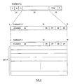
- Fig. 2 shows formats used in the serial transmission line 9 between the local channel control device 2 and the remote channel control device 3.
- Format A is used to perform the transmission of the data or the status information.
- a portion 21 of the format A includes flags (F), address (A) of the local or remote channel control device 2 or 3 and control data (c).
- a portion 22 is used to transmit format B or format C.
- a portion 23 includes frame check sequence (FCS) and flags (F).
- 16 byte format B is used to transmit latter described various messages between the local channel control device 2 and the remote channel control device 3.
- Header portion 25 includes the address of the control unit, length of the format B, information indicating data chaining, etc.
- Two byte portion 26 is used for message code.
- One byte portion 27 is used for the address.
- Two byte portion 29 is used for type information, Type 1, Type 2 or Type 3, as described hereinafter.
- Format C is used for transmitting data between the local channel control device 2 and the remote channel control device 3. The 16 bytes are followed by the data. Therefore, the format C includes the 16 bytes and the data.
- the local channel control device 2 sends an initial status to the host channel depending upon the received command and address, to the host channel.
- the local channel control device 2 includes an initial status table 21 accessed by the command and the address.
- the host channel responds the initial status to control the connection and the disconnection of the local channel control device 2.
- the address used in the specification means the address of the control unit when only one I/O device is connected to the control unit, or the addresses of both the control unit and I/O device when plural I/O devices are connected to the control unit.
- Processing patterns or types of operations are selected depending upon as to whether the addressed control unit is provided with a data buffer memory, or not.
- the control unit 4 is provided with a data buffer memory, whereas the control unit 5 is not provided with a data buffer memory.
- the control unit 4 can store the data in its own data buffer memory. Accordingly, the control unit 4, in the READ operation, can store the data sent from the I/O device; and when a re-transmission of the data due to a transmission error, for example, is requested, the data is re-transmitted from the data buffer memory of the control unit 4 to the remote channel control device 3 without re-operating the I/O device.
- the control unit 4 in the WRITE operation, can store the data sent from the remote channel control device 3; and when a re-transmission of data due to a printer error, for example, is requested, the data is resent from the data buffer memory of the control unit 4 to the printer without re-transmitting the data from the remote channel control device 3.
- the control unit 4 can recover the error without requesting the re-transmission of the data from the data source.
- the control unit 5 cannot store the data and only passes the data. Accordingly, the control unit 5, in the READ operation, passes the data sent from the I/O device, such as a tape unit to the remote channel control device 3. When the re-transmission of the data is required due to the error, the tape unit must be connected again and the data is re-transmitted from the tape unit to the remote channel control device 3 through the control unit 5.
- the control unit 5, in the WRITE operation also passes the data sent from the remote channel control device 3 to the printer, for example. When the re-transmission of the data is required, the data must be re-sent from the remote channel control device 3 to the printer through the control unit 5. Thus, control unit 5 requires the re-connection of the data source to recover the error.
- the type 1 operation processes READ or WRITE command to the control unit 5 without the data buffer memory.
- the type 1 operation processes the command which requires the data transfer sequence, requires X'00' as an initial status, requires X'08' as an ending status and requires X'04' as an asynchronous status.
- the X'00' represents that the command is accepted.
- the local and remote channel control devices receive the X'00", they can proceed to the next operation.
- the X'08' (Channel end) represents that the operations of the command on the channel have been completed without error, e.g. error of the number of data, parity error, etc.
- the X'08' is sent at the receive of the X'00' from the control unit, based upon the assumption that the data transfer will be completed without the error.
- the X'04' (Device end) represents that the control unit or the I/O device has received the data, and the host channel can erase the data and process the next command.
- the X'4A' makes the host channel to perform the command retry when the host channel receives the X'04' from the local channel control device 2.
- the type 2 operation is used for processing the READ or WRITE command to the control unit 4 with the data buffer memory.
- the commands require the data transfer sequence, require the X'00' as the initial status, and require the X'0C' as the ending status.
- the TYPE 3 operation processes the CONTROL command, which requires the X'08' as the initial status, and requires the X'04' as the asynchronous status.
- the type 3 operation processes the CONTROL command, such as SPACE, STOP, REWIND which changes a condition of the I/O device.
- Fig. 3 shows the details of the local channel control device 2 and the remote channel control device 3.
- the local channel control device 2 includes a microprocessor (MPU) 20, an initial status table 21, a type information table 22 and a data buffer memory 23.
- the MPU 20 controls the operations and the data buffer memory 23 stores the data.
- the remote channel control device 3 includes MPU 27 which controls the operations of the device 3 and a data buffer memory 28 which stores the data.
- the MPU 20 in the local channel control device 2 receives the command and the address; sends a message, which represents the command, the address and the type information, to the remote channel control device 3; sends the status to the host channel; and controls the transmission of data.
- the MPU 27 in the remote channel control device 3 responds the message from the local channel control device 2 to control the control unit 4 or 5 and the transmission of data.
- Fig. 4A shows the initial status table 21 which stores various initial statuses, one of which is fed back to the host channel in accordance with the command and the address of the control unit when these are supplied from the host channel to the local channel control device 2.
- One of the statuses is accessed by the command and the address. In other words, one of the initial statuses is selected depending upon the command and the address of the control unit.
- Fig. 4B shows the type information table 22 which stores the type information, i.e. Type 1, Type 2 and Type 3, one of which is selected depending upon the command and the address of the control unit supplied from the host channel to the local channel control device 2.
- the local channel control device 2 therefore, decodes the command and the address supplied from the host channel to send back the initial status to the host channel depending upon the received command and the address, and to send both the command and address along with the type information, i.e. Type 1, Type 2 or Type 3, which is selected depending upon the command and the address, to the remote channel control device 3.
- type information i.e. Type 1, Type 2 or Type 3, which is selected depending upon the command and the address
- Figs. 5, 6, 7, 8 and 9 show various operations between the host channel and the local channel control device 2, between the local channel control device 2 and the remote channel control device 3, and between the remote channel control device 3 and the control unit.
- Operational sequences between the host channel and the local channel control device 2 and between the remote channel control device 3 and the control unit are, as follows.
- the command and the address are sent, and the initial status are sent back between the host channel and the local channel control device 2, and between the remote channel control device 3 and the control unit.
- the data is sent between the host channel and the local channel control device 2 and between the remote channel control device 3 and the control unit.
- the ending status is sent between the host channel and the local channel control device 2 and between the remote channel control device 3 and the control unit.
- asynchronous status is sent between the host channel and the local channel control device 2 and between the remote channel control device 3 and the control unit.
- Messages transmitted between the local channel control device 2 and the remote channel control device 3 are, as follows.
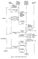
- the Fig. 5 shows the TYPE 1 WRITE operation wherein the data is sent from the host unit 1 to the control unit 5 without the data buffer memory and the I/O device 13.
- the host channel supplies the local channel control device 2 WRITE command and the control unit address X'61' of the control unit 5 without the data buffer memory.
- the WRITE command and the address X'61' are supplied to the initial status table 21, so that the initial status X'00' (Command normally accepted) is selected, and the local channel control device 2 sends the host channel the selected initial status X'00', as shown in the Fig. 5.
- the WRITE command and the address X'61' are also supplied to the information table 22 of the local channel control device 2, as shown in the Figs. 3 and 4B, so that the type information, i.e.
- TYPE 1 is selected, and the local channel control device 2 sends the remote channel control device 3 the WRITE command, the address X'61' and the selected type information TYPE 1, as the ISSINF (Initial selection information).
- the host channel responds to the X'00' to transmit the data to the local channel control device 2 during DTS (Data transfer sequence).
- the control device 2 sends the remote channel control device 3 the message DTSCMP (Data transfer complete), and transmits the remote channel control device 3 the data.
- the remote channel control device 3 sends the WRITE command and the address X'61' to the control unit 5 during the ISS, after receiving the data.
- the control unit 5 sends the initial status X'00' to the remote channel control device 3, which passes the X'00' along with the message ISSTAT to the local channel control device 2.
- the control device 2 responds the X'00' to send the ending status X'08' (Channel end) to the host channel during the ES (Ending status transfer sequence). That is, the control device 2 sends the ending status X'08' at the time the remote channel control device 3 has received the data and the control unit 5 has sent the initial status X'00' to the local channel control device 2. It is noted that the X'08' is generated at the receive of the X'00' from the control unit 5 based upon the assumption that the data transfer will be completed without the error.
- the host channel sends a signal representing Accept of the X'08' on the tag line Service Out to the local channel control device 2, which sends the message ESCOND representing that the host channel accepted the X'08', to the remote channel control device 3. And, the host channel disconnects the local channel control device 2, and can perform other jobs.
- the remote channel control device 3 After sending the ISSTAT X'00', the remote channel control device 3 sends the data to the control unit 5 during the DTS.
- the control unit 5 sends the ending status X'08' to the remote channel control device 3 during the ES after receiving the data; and sends the asynchronous status X'04' during the CUIS after sending the data to the I/O device 13.
- the remote channel control device 3 stacks the X'04'.
- the stack means that the remote channel control device 3 does not accept the X'04' (Device end), but knows the arrival of the X'04' and can read the X'04'.
- the reasons for stacking the X'04' are as follows. If the remote channel control device 3 accepts the X'04', the control unit 5 understands as that the operation of the WRITE command was completed, and can not respond to RESET, CHAINNING, etc., which is latter sent from the host channel in this WRITE operation. The stack makes the control unit 5 to respond the RESET or CHAINNING latter sent from the host channel.
- the remote channel control device 3 sends ASYNDE (X'04') to the local channel control device 3, which sends CUIS STAT X'04' to the host channel during the CUIS.
- the host channel responds the X'04' by sending the control device 2 a signal on the tag line Service Out if accepts the X'04'; or sends RESET or CHAINNING on the respective tag lines to the control device 2 if these are required.
- the local channel control device 2 sends the message ASCOND indicating the host channel response to the remote channel control device 3.
- the host channel response is ACCEPT
- the control device 3 accepts the ASYN STAT X'04' at this time, and the WRITE operation is completed.
- the host channel response is RESET
- the RESET is sent to the control unit 5 for performing the RESET operation.
- TEST I/O TIO
- control unit 5 sends the status X'08' to the remote channel control device 3 when the control unit 5 has passed the data to the I/O device 13; and sends the status X'04' to the remote channel control device 3 when the I/O device 13 has processed the data.
- the reasons for separately generating the statuses X'08' and X'04' are that the control unit 5 does not have the data buffer memory, and cannot generate the X'04' (Device end) until the I/O device 13 has processed the data.
- the host channel connects the local channel control device 2 from the ISS (Initial selection sequence) to the ES (Ending status transfer sequence); disconnects the control device 2 until the CUIS (Control unit initiated sequence); and connects again the control device 2 during the CUIS, as shown in the Fig. 5.
- the host channel therefore, can perform other jobs during the disconnected period.
- the remote channel control device 3 is connected to the control unit 5 during the connection periods, and is disconnected from the control unit 5 during the disconnection periods shown in the Fig. 5.
- the control device 3 can receive the ASYN STAT from the control unit 5 in the CUIS during the disconnected period.
- the control device 3 can perform job of other control unit during the disconnected period.
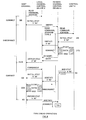
- the Fig. 6 shows the TYPE 1 READ operation wherein the data is sent from the I/O device 13 and the control unit 5 without the data buffer memory to the host unit 1.
- the host channel sends the local channel control device 2 the READ command and the address X'61' of the control unit 5.
- the READ command and the address X'61' are supplied to the initial status table 21 and the information table 22 to select the initial status X'4A' and the Type information or TYPE 1, respectively.
- the local channel control device 2 sends the initial status X'4A' to the host channel, which responds the X'4A' to disconnect the local channel control device 2, as shown in the Fig. 6.
- the initial status X'4A' means the command retry which makes the host channel to perform the command retry when the host channel receives X'04' (Device end) from the local channel control device 2.
- the local channel control device 2 sends the READ command, the address X'61' and the type information or TYPE 1 to the remote channel control device 3 as the message ISSINF.
- the control device 3 sends the READ command and the address X'61' to the control unit 5, which sends back the initial status X'00' to the control device 3 during the ISS.
- the message ISSTAT X'00' is sent from the control device 3 to the control device 2.
- the data from the I/O device is read and sent to the remote channel control device 3.
- the control device 3 When the control device 3 has received the data, it sends the message DTSCMP to the control device 2, and sends the data to the control device 2.
- the control unit 5 sends the ending status X'08' during the ES to the control device 3, which stacks the X'08'. That is, the control device 3 does not accept the X'08' at this time, but reads the X'08', and sends the message ESSTAT to the control device 2.
- the local channel control device 2 When the local channel control device 2 receives the data, it sends asynchronous status X'04' to the host channel during CUIS. It is noted that the host channel was supplied with the initial status X'4A' during the ISS, which makes the host channel to perform the command retry when it receives the X'04'. The host channel, therefore, responds the X'04' to perform the command retry, so that it sends again the READ command and the address X'61' to the local channel control device 2, and the control device 2 sends the initial status X'00' to the host channel during the ISS. The control device 2 sends the data to the host channel during the DTS and sends the ending status X'08' to the host channel.
- the host channel responds the X'08' to send the response, such as RESET, ACCEP, CHAINNING to the control device 2, and disconnects the control device 2.
- the control device 2 sends the response to the control device 3 as the message ESCOND. If the response of the host channel is ACCEPT, the control device 3 accepts the ending status X'08' which was stacked in the ES. If the response is RESET, the RESET is informed to the control unit 5 and the unit 5 resets the operation. In the exemplary case, the X'08' is accepted, and the control unit 5 sends the X'04' to the control device 3 during the CUIS. The X'04' is also stacked.
- the control device 3 sends ASYNDE (X'04') to the control device 2, which sends the X'04' to the host channel during CUIS.
- the host channel sends the response, e.g. ACCEPT, to the control device 2, which sends the ASCOND (ACCEPT) to the control device 3, so that, at this time the control device 3 accepts the X'04' which was stacked in the CUIS, and the READ operation is completed.
- control device 2 is connected to the host channel during the ISS, disconnected until the CUIS, connected until the ES, disconnected until the CUIS, and connected during the CUIS, whereby the host-channel can perform other jobs during the disconnected periods.
- connection between the remote channel control device 3 and the control unit 5 is connected and disconnected as shown in the Fig. 6, whereby the control device 3 can perform jobs from the other control units during the disconnected periods.
- control unit 5 sends the status X'08' to the remote channel control device 3 when the control device 5 has passed the data from the I/O device 13 to the remote channel control device 3; and sends the status X'04' to the remote channel control device 3 when the I/O device has informed the control unit 5 of the actual end of the READ operation.
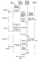
- the Fig. 7 shows the TYPE 2 WRITE operation wherein the data is written from the host unit 1 to the control unit 4 with the data buffer memory and the I/O device 12.
- the host channel sends the local channel control device 2 the WRITE command and the address X'62' of the control unit 4 with the data buffer memory.
- the WRITE command and the I/O device address X'62' are supplied to the initial status table 21 and the information table 22 to select the initial status X'00' and the type information or TYPE 2, respectively.
- the local channel control device 2 sends the initial status X'00' to the host channel during the ISS.
- the local channel control device 2 sends the WRITE command, the address X'62' and the type information or TYPE 2 as the message ISSINF to the remote channel control device 3.
- the host channel sends the data to the local channel control device 2.
- the control device 2 sends the DTSCMP to the control device 3 and sends the data to the control device 3.
- the control device 3 sends the received WRITE command and the address X'62' to the control unit 4 during the ISS.
- the control unit 4 sends the initial status X'00' to the control device 3, which sends the X'00' to the control device 2, which responds the X'00' to send the ending status X'08' to the host channel during the ES.
- the host channel responds the X'08' to send its response i.e. a signal on the tag line, such as ACCEPT RESET, etc. In this case, it is assumed that the host channel response is ACCEPT.
- the remote channel control device 3 sends the data to the control unit 4 during the DTS, after sending the status X'00' to the control device 2.
- the control unit 4 When the control unit 4 has received the data, it sends the ending status X'0C' to the control device 3 during the ES.
- the control device 3 stacks the X'0C', and sends the ESSTAT X'0C' to the control device 2, which sends the asynchronous status X'04' to the host channel.
- the host channel responds the X'04' to send its response to the control device 2 and disconnects the control device 2.
- the control device 2 sends ASCOND, i.e. the host channel response, to the control device 3. It is assumed that the response is ACCEPT. Thus, at this time the control device 3 accepts the ending status X'0C' received in the ES. The WRITE operation is thereby completed.
- the reasons for stacking the X'0C' are as follows. At the ES, the data has been stored in the control unit 4 or the I/O device. If the X'0C' is accepted by the control device 3 during the ES, the control unit 4 considers as that the data transfer in the WRITE operation has completed without DISCONNECT, RESET, CHAINNING etc. It for example RESET, is sent by the host channel to reset the operation at the time it is received, and to clear the stored data. If the host channel sends the response RESET to the control unit 4 after the X'0C' had been accepted during the ES, the data stored in the control unit 4 or the I/O device can not be cleared, thus an integration of operations is lost.
- the control unit 4 sends the status X'0C' (Channel end and Device end) when the control unit 4 has received the data from the remote channel control device 3 into its data buffer memory.
- the reasons for generating the X'0C' are that the data has been stored in the data buffer memory of the control unit 4 and it is deemed that the I/O device 12 has processed the data.
- the host channel connects the local channel control device 2 from the ISS to the ES, disconnects it until the CUIS, and connects it during the CUIS, and can perform other jobs during the disconnected period.
- the remote channel control device 3 is also disconnected, as shown in the Fig. 7, and can perform jobs of the other control unit during the disconnected period.
- Fig. 8 shows the TYPE 2 READ operation wherein the data is sent from the I/O device 12 and the control unit 4 with the data buffer memory to the host unit 1.
- the host channel sends the control device 2 the READ command and the address X'62' of the control unit 4 with the data buffer memory.
- the READ command and the address X'62' are supplied to the initial status table 21 and the type information table 22 of the local channel control device 2 to select the initial status X'4A' and the type information or TYPE 2, respectively.
- the control device 2 sends the X'4A' to the host channel during the ISS, and sends the READ command, the address X'62' and the type information TYPE 2 to the remote channel control device 3 as the message ISSINF.
- the host channel responds the X'4A' to disconnect the control device 2.
- the X'4A' makes the host channel to perform the command retry when the host channel receives the X'04' from the local channel control device 2.
- the control device 3 sends the READ command and the address X'62' to the control unit 4, which sends back the initial status X'00' to the control device 3 during the ISS.
- the control device 3 then sends the X'00' to the control device 2.
- the data is read from the I/O device 12 to the control unit 4 and sent to the remote channel control device 3 during the DTS.
- the control device 3 When the control device 3 has received the data, it sends the message DTSCMP to the local channel control device 2.
- the control unit 4 sends the ending status X'0C' to the control device 3 during ES, which stacks the status X'0C' and sends the X'0C' to the control device 2.
- the data is sent from the control device 3 to the control device 2.
- the control device 2 sends the asynchronous status X'04' to the host channel during CUIS, which responds the X'04' to start the command retry to re-send the READ command and the address X'62' to the local channel control device 2, which sends back the X'00' to the host channel in the ISS.
- the data is sent from the control device 2 to the host channel in DTS.
- the control device 2 sends the ending status X'0C' to the host channel during the ES.
- the host channel sends a signal on the tag line representing its response and disconnects the control device 2.
- the response i.e. ESCOND, is sent from the control device 2 to the control device 3. If the response is ACCEPT, the control device 3 accepts at this time the ending status X'0C' received in the ES. If the response is RESET, the data is cleared. The READ operation is thereby completed.
- the host channel connects the control device 2 during the ISS, disconnects until the CUIS, and connects until the ES; and the remote channel control device 3 connects and disconnects the control unit 4, as shown in the Fig. 8. During the disconnected period, the host channel can perform other jobs, and the remote channel control device 3 can perform jobs of other control unit.
- control unit 4 sends the status X'0C' to the remote channel control device 3 when the data in the data buffer memory of the control unit 4 has been sent to the remote channel control device 3.
- the Fig. 9 shows the TYPE 3 operation wherein a command, such as CONTROL, without the data transfer is processed.
- the CONTROL command is used to directly control the condition of the I/O device.
- the host channel sends the CONTROL command and the address X'62' of the control unit 4, for example, to which the I/O device is connected, to the local channel control device 2 during the ISS.
- the CONTROL command and the address X'62' are supplied to the initial status table 21 and the type information table 22 to select the initial status X'4A' and the type information TYPE 3.
- the initial status X'4A' is sent to the host channel during the ISS, which responds the X'4A' to disconnect the control device 2.
- the control device 2 sends the CONTROL command, the address X'62' and the type information TYPE 3 to the control device 3, which sends the CONTROL command and the address X'62' to the control unit 4 during ISS, which sends the initial status X'08' to the control device 3.
- the control device 3 stacks the X'08', and sends the X'08' to the control device 2.
- the control device 2 sends the asynchronous status X'04' to the host channel, which responds the X'04' to perform the command retry by sending again the CONTROL command and the address X'62' to the control device 2; sends its response to the X'08' to the control device 2; and disconnects the control device 2.
- the control device 2 sends the host unit response ESCOND to the control device 3. It is assumed the host response is ACCEPT.
- the remote channel control device 3 accepts, at this time, the X'08' stacked during ISS.
- the control unit 4 sends the asynchronous status X'04' to the control device 3, which stacks the X'04', and sends the ASYNDE X'04' to the control device 2, which sends the X'04' to the host channel.
- the host channel responds the X'04' to send its response, e.g. ACCEPT, to the control device 2, and disconnects the local channel control device 2.
- the control device 2 sends the host unit response ASCOND to the control device 3, which, at this time, accepts the X'04' stacked during the CUIS. The operation of the CONTROL command is thereby completed.
- the host channel connects and disconnects the local channel control device 2, and the remote channel control device 3 connects and disconnects the control unit 4, as shown in the Fig. 9.
- the host channel and the remote channel control device 3 can perform other jobs during the disconnected period, respectively.
- additional plural remote channel control devices can be connected to the remote channel control device 3 in a multi-drop connection.
Applications Claiming Priority (2)
| Application Number | Priority Date | Filing Date | Title |
|---|---|---|---|
| JP317910/89 | 1989-12-08 | ||
| JP1317910A JPH03189752A (ja) | 1989-12-08 | 1989-12-08 | データ処理システム |
Publications (2)
| Publication Number | Publication Date |
|---|---|
| EP0431949A2 true EP0431949A2 (de) | 1991-06-12 |
| EP0431949A3 EP0431949A3 (en) | 1993-11-18 |
Family
ID=18093416
Family Applications (1)
| Application Number | Title | Priority Date | Filing Date |
|---|---|---|---|
| EP19900313284 Withdrawn EP0431949A3 (en) | 1989-12-08 | 1990-12-06 | Data processing system with channel control means |
Country Status (3)
| Country | Link |
|---|---|
| US (1) | US5204950A (de) |
| EP (1) | EP0431949A3 (de) |
| JP (1) | JPH03189752A (de) |
Cited By (5)
| Publication number | Priority date | Publication date | Assignee | Title |
|---|---|---|---|---|
| EP0859324A2 (de) * | 1997-02-14 | 1998-08-19 | Canon Kabushiki Kaisha | Vorrichtung, System und Verfahren zur Datenübertragung und Vorrichtung zur Bildverarbeitung |
| CN1084898C (zh) * | 1995-03-15 | 2002-05-15 | 三菱电机株式会社 | 多计算机系统 |
| US7062579B2 (en) | 1997-02-14 | 2006-06-13 | Canon Kabushiki Kaisha | Data transmission apparatus, system and method, and image processing apparatus |
| US7213138B2 (en) | 1997-02-14 | 2007-05-01 | Canon Kabushiki Kaisha | Data transmission apparatus, system and method, and image processing apparatus |
| US7401213B2 (en) | 1997-02-14 | 2008-07-15 | Canon Kabushiki Kaisha | Data communication apparatus and method of a device that supports plural communication methods |
Families Citing this family (8)
| Publication number | Priority date | Publication date | Assignee | Title |
|---|---|---|---|---|
| US5392397A (en) * | 1992-03-30 | 1995-02-21 | International Business Machines Corporation | Command execution system for using first and second commands to reserve and store second command related status information in memory portion respectively |
| US5459838A (en) * | 1992-09-24 | 1995-10-17 | International Business Machines Corporation | I/O access method for using flags to selectively control data operation between control unit and I/O channel to allow them proceed independently and concurrently |
| US5388210A (en) * | 1993-05-17 | 1995-02-07 | The United States Of America As Represented By The Secretary Of The Navy | Programmable modular network interface for coupling a computer and a plurality of workstation consoles |
| JP3599408B2 (ja) * | 1995-03-15 | 2004-12-08 | キヤノン株式会社 | 通信システム及び通信装置及び通信制御方法 |
| US5664219A (en) * | 1995-06-12 | 1997-09-02 | International Business Machines Corporation | Method and system for controlling servicability of adapters connected by an I/O channel interface to a computer system |
| US7013305B2 (en) | 2001-10-01 | 2006-03-14 | International Business Machines Corporation | Managing the state of coupling facility structures, detecting by one or more systems coupled to the coupling facility, the suspended state of the duplexed command, detecting being independent of message exchange |
| US10019203B1 (en) * | 2013-05-30 | 2018-07-10 | Cavium, Inc. | Method and system for processing write requests |
| JP7032631B2 (ja) | 2017-07-04 | 2022-03-09 | 富士通株式会社 | 送受信システム、送受信システムの制御方法、及び送信装置 |
Citations (4)
| Publication number | Priority date | Publication date | Assignee | Title |
|---|---|---|---|---|
| EP0071782A2 (de) * | 1981-08-10 | 1983-02-16 | International Business Machines Corporation | Mehrunterkanaladapter mit einem einzelnen Zustands-/Adressen-Register |
| JPS58119028A (ja) * | 1982-01-11 | 1983-07-15 | Nippon Telegr & Teleph Corp <Ntt> | 入出力装置接続方式 |
| JPS61288232A (ja) * | 1985-06-17 | 1986-12-18 | Fujitsu Ltd | 出力命令制御方式 |
| US4805137A (en) * | 1987-01-08 | 1989-02-14 | United Technologies Corporation | Bus controller command block processing system |
Family Cites Families (1)
| Publication number | Priority date | Publication date | Assignee | Title |
|---|---|---|---|---|
| US4015243A (en) * | 1975-06-02 | 1977-03-29 | Kurpanek Horst G | Multi-processing computer system |
-
1989
- 1989-12-08 JP JP1317910A patent/JPH03189752A/ja active Granted
-
1990
- 1990-11-28 US US07/619,788 patent/US5204950A/en not_active Expired - Fee Related
- 1990-12-06 EP EP19900313284 patent/EP0431949A3/en not_active Withdrawn
Patent Citations (4)
| Publication number | Priority date | Publication date | Assignee | Title |
|---|---|---|---|---|
| EP0071782A2 (de) * | 1981-08-10 | 1983-02-16 | International Business Machines Corporation | Mehrunterkanaladapter mit einem einzelnen Zustands-/Adressen-Register |
| JPS58119028A (ja) * | 1982-01-11 | 1983-07-15 | Nippon Telegr & Teleph Corp <Ntt> | 入出力装置接続方式 |
| JPS61288232A (ja) * | 1985-06-17 | 1986-12-18 | Fujitsu Ltd | 出力命令制御方式 |
| US4805137A (en) * | 1987-01-08 | 1989-02-14 | United Technologies Corporation | Bus controller command block processing system |
Non-Patent Citations (2)
| Title |
|---|
| PATENT ABSTRACTS OF JAPAN vol. 11, no. 153 (P-577)19 May 1987 & JP-A-61 288 232 ( FUJITSU ) 18 December 1986 * |
| PATENT ABSTRACTS OF JAPAN vol. 7, no. 231 (P-229)13 October 1983 & JP-A-58 119 028 ( NIPPON DENSHIN ) 15 July 1983 * |
Cited By (8)
| Publication number | Priority date | Publication date | Assignee | Title |
|---|---|---|---|---|
| CN1084898C (zh) * | 1995-03-15 | 2002-05-15 | 三菱电机株式会社 | 多计算机系统 |
| EP0859324A2 (de) * | 1997-02-14 | 1998-08-19 | Canon Kabushiki Kaisha | Vorrichtung, System und Verfahren zur Datenübertragung und Vorrichtung zur Bildverarbeitung |
| EP0859324A3 (de) * | 1997-02-14 | 1999-05-19 | Canon Kabushiki Kaisha | Vorrichtung, System und Verfahren zur Datenübertragung und Vorrichtung zur Bildverarbeitung |
| US6603737B1 (en) | 1997-02-14 | 2003-08-05 | Canon Kabushiki Kaisha | Data transmission apparatus, system and method, and image processing apparatus |
| US7062579B2 (en) | 1997-02-14 | 2006-06-13 | Canon Kabushiki Kaisha | Data transmission apparatus, system and method, and image processing apparatus |
| US7213138B2 (en) | 1997-02-14 | 2007-05-01 | Canon Kabushiki Kaisha | Data transmission apparatus, system and method, and image processing apparatus |
| US7401213B2 (en) | 1997-02-14 | 2008-07-15 | Canon Kabushiki Kaisha | Data communication apparatus and method of a device that supports plural communication methods |
| US7430660B2 (en) | 1997-02-14 | 2008-09-30 | Canon Kabushiki Kaisha | Data transmission apparatus, system and method, and image processing apparatus |
Also Published As
| Publication number | Publication date |
|---|---|
| JPH03189752A (ja) | 1991-08-19 |
| JPH0526221B2 (de) | 1993-04-15 |
| US5204950A (en) | 1993-04-20 |
| EP0431949A3 (en) | 1993-11-18 |
Similar Documents
| Publication | Publication Date | Title |
|---|---|---|
| US6434643B1 (en) | Transmission of status information by a selected one of multiple transfer modes based on the cause for sending the status information | |
| EP0431949A2 (de) | Datenverarbeitungssystem mit Kanalsteuerungsmitteln | |
| EP0471354A2 (de) | Schnittstellenschaltung für intelligentes Netzwerk | |
| US4896151A (en) | Simultaneous communication method and system | |
| US5944797A (en) | Data mover hardware controlled processing in a commanding system and in a commanded system for controlling frame communications on a link | |
| US4675864A (en) | Serial bus system | |
| JPS604624B2 (ja) | 正しくない情報フレ−ムを再送するシステム | |
| JP3028815B2 (ja) | 携帯可能電子装置の伝送方法と携帯可能電子装置 | |
| EP0496177A1 (de) | Verfahren zur Übertragung von Daten zwischen einem Wirtsrechner und einer Datenübertragungsteuerung durch Verkettung von Puffern | |
| EP0639016A2 (de) | Vielzahlknoten-Datenverarbeitungssystem | |
| EP0242634A2 (de) | Bytezählergebnisbehandlung in einer seriellen Kanalerweiterung mit Pufferung von vorausgeholten Daten | |
| EP0336547B1 (de) | Rechnernetzwerk und Verfahren zum Betreiben desselben | |
| EP0115348A2 (de) | Ferninitialisierung von verbundenen Datenstationen | |
| JP4112717B2 (ja) | データ処理装置 | |
| US4612541A (en) | Data transmission system having high-speed transmission procedures | |
| US20020116566A1 (en) | Data transmitting and receiving system, and data receiving device | |
| EP0482828B1 (de) | Nachrichtenbezogene Steuerungsschnittstelle | |
| US5559972A (en) | Method and apparatus for supporting byte-mode devices and non-byte-mode devices on a bus | |
| JP2776274B2 (ja) | 中継計算機における仮想バッファ制御システム | |
| JPH06290144A (ja) | 受信バッファ制御装置 | |
| JPS59158641A (ja) | デ−タ伝送方式 | |
| JP2848442B2 (ja) | 任意メッセージデータ判別方式 | |
| JP3429510B2 (ja) | パケット通信装置 | |
| JP2000022743A (ja) | 非同期データ通信方法 | |
| JP3388806B2 (ja) | シリアルインタフェイス制御を用いるプリンタ装置 |
Legal Events
| Date | Code | Title | Description |
|---|---|---|---|
| PUAI | Public reference made under article 153(3) epc to a published international application that has entered the european phase |
Free format text: ORIGINAL CODE: 0009012 |
|
| AK | Designated contracting states |
Kind code of ref document: A2 Designated state(s): DE FR GB |
|
| 17P | Request for examination filed |
Effective date: 19911018 |
|
| PUAL | Search report despatched |
Free format text: ORIGINAL CODE: 0009013 |
|
| AK | Designated contracting states |
Kind code of ref document: A3 Designated state(s): DE FR GB |
|
| 17Q | First examination report despatched |
Effective date: 19960125 |
|
| STAA | Information on the status of an ep patent application or granted ep patent |
Free format text: STATUS: THE APPLICATION IS DEEMED TO BE WITHDRAWN |
|
| 18D | Application deemed to be withdrawn |
Effective date: 19961008 |