EP0431419A1 - Garniture mécanique et dispositif pour assurer l'étanchéité d'un tuyau en rotation contre un bâti fixe - Google Patents
Garniture mécanique et dispositif pour assurer l'étanchéité d'un tuyau en rotation contre un bâti fixe Download PDFInfo
- Publication number
- EP0431419A1 EP0431419A1 EP90122423A EP90122423A EP0431419A1 EP 0431419 A1 EP0431419 A1 EP 0431419A1 EP 90122423 A EP90122423 A EP 90122423A EP 90122423 A EP90122423 A EP 90122423A EP 0431419 A1 EP0431419 A1 EP 0431419A1
- Authority
- EP
- European Patent Office
- Prior art keywords
- rail
- ring
- roller
- mechanical seal
- counter
- Prior art date
- Legal status (The legal status is an assumption and is not a legal conclusion. Google has not performed a legal analysis and makes no representation as to the accuracy of the status listed.)
- Granted
Links
Images


Classifications
-
- F—MECHANICAL ENGINEERING; LIGHTING; HEATING; WEAPONS; BLASTING
- F27—FURNACES; KILNS; OVENS; RETORTS
- F27D—DETAILS OR ACCESSORIES OF FURNACES, KILNS, OVENS, OR RETORTS, IN SO FAR AS THEY ARE OF KINDS OCCURRING IN MORE THAN ONE KIND OF FURNACE
- F27D99/00—Subject matter not provided for in other groups of this subclass
- F27D99/0073—Seals
-
- F—MECHANICAL ENGINEERING; LIGHTING; HEATING; WEAPONS; BLASTING
- F16—ENGINEERING ELEMENTS AND UNITS; GENERAL MEASURES FOR PRODUCING AND MAINTAINING EFFECTIVE FUNCTIONING OF MACHINES OR INSTALLATIONS; THERMAL INSULATION IN GENERAL
- F16J—PISTONS; CYLINDERS; SEALINGS
- F16J15/00—Sealings
- F16J15/16—Sealings between relatively-moving surfaces
- F16J15/34—Sealings between relatively-moving surfaces with slip-ring pressed against a more or less radial face on one member
- F16J15/36—Sealings between relatively-moving surfaces with slip-ring pressed against a more or less radial face on one member connected by a diaphragm or bellow to the other member
-
- F—MECHANICAL ENGINEERING; LIGHTING; HEATING; WEAPONS; BLASTING
- F16—ENGINEERING ELEMENTS AND UNITS; GENERAL MEASURES FOR PRODUCING AND MAINTAINING EFFECTIVE FUNCTIONING OF MACHINES OR INSTALLATIONS; THERMAL INSULATION IN GENERAL
- F16L—PIPES; JOINTS OR FITTINGS FOR PIPES; SUPPORTS FOR PIPES, CABLES OR PROTECTIVE TUBING; MEANS FOR THERMAL INSULATION IN GENERAL
- F16L27/00—Adjustable joints, Joints allowing movement
- F16L27/12—Adjustable joints, Joints allowing movement allowing substantial longitudinal adjustment or movement
- F16L27/125—Adjustable joints, Joints allowing movement allowing substantial longitudinal adjustment or movement having longitudinal and rotary movement
-
- F—MECHANICAL ENGINEERING; LIGHTING; HEATING; WEAPONS; BLASTING
- F27—FURNACES; KILNS; OVENS; RETORTS
- F27B—FURNACES, KILNS, OVENS, OR RETORTS IN GENERAL; OPEN SINTERING OR LIKE APPARATUS
- F27B7/00—Rotary-drum furnaces, i.e. horizontal or slightly inclined
- F27B7/20—Details, accessories, or equipment peculiar to rotary-drum furnaces
- F27B7/22—Rotary drums; Supports therefor
- F27B7/24—Seals between rotary and stationary parts
-
- F—MECHANICAL ENGINEERING; LIGHTING; HEATING; WEAPONS; BLASTING
- F27—FURNACES; KILNS; OVENS; RETORTS
- F27D—DETAILS OR ACCESSORIES OF FURNACES, KILNS, OVENS, OR RETORTS, IN SO FAR AS THEY ARE OF KINDS OCCURRING IN MORE THAN ONE KIND OF FURNACE
- F27D17/00—Arrangements for using waste heat; Arrangements for using, or disposing of, waste gases
- F27D17/001—Extraction of waste gases, collection of fumes and hoods used therefor
- F27D17/002—Details of the installations, e.g. fume conduits or seals
Definitions
- the invention relates to a mechanical seal for sealing a rotatable tube against a standing housing.
- Such mechanical seals and suitable methods for sealing a rotatable tube against a standing housing are known.
- a compensator is used which consists of a flexible material, for example an impregnated fabric. This compensator is necessary so that different thermal expansions of the pipe and the housing can be compensated and that no damage to one of the components can occur. Different thermal expansions of the tube and the housing are to be expected especially if there is a temperature change in the tube due to combustion.
- the tube assigned to a housing can be, for example, a smoldering drum known from EP-A-0 302 310. There is a gas space in the upright housing, which must be sealed by the mechanical seal against the interior of the tube, in which charring of waste takes place.
- the smoldering drum is a component of a system for carrying out a smoldering-burning process.
- the positioned counter ring must also be pressed against the sealing ring using suitable means. This is the only way to achieve a gas-tight seal. So far, mechanical, pneumatic or hydraulic means have been used for this. Common means are brackets that enclose the sealing ring and counter ring on the circumference. The brackets are equipped with mechanical springs, pneumatic cylinders or hydraulic cylinders that press the sealing ring and counter ring against each other.
- the usual supporting structures or supporting devices for the counter ring and compensator require complex monitoring, since they have to be tracked in the event of heat-related displacements of the counter ring. Care must be taken that the mating ring is always kept stable in the carrying device and does not slip off the carrying device.
- the usual means of pressing the counter ring onto the sealing ring also require constant monitoring. Care must be taken that the contact pressure of the mechanical spring, the pneumatic cylinder or the hydraulic cylinder is always sufficiently large.
- the invention has for its object to provide a mechanical seal in which the counter ring is always positioned sufficiently centered on the sealing ring without the position of a support device having to be monitored.
- a mechanical seal should also be specified, in which no means are required to press the counter ring onto the sealing ring, which means that frequent monitoring is required.
- a mechanical seal for sealing a rotatable tube against a stationary housing with a sealing ring rotatable with the pipe and connected to the pipe and coaxial with the pipe, with a mating ring connected to the housing via a flexible compensator for compensating changes in length of the tube, which can be pressed with an end sealing surface against an end sealing surface of the sealing ring for sealing the housing against the tube, with at least one roller arranged to support the counter ring and the compensator on the peripheral surface of the counter ring, the axis of rotation of which is perpendicular to the peripheral surface of the counter ring, and with at least one rail which is fastened to the stationary housing and on which the at least one roller is supported and can be moved in a rolling manner.
- the counter ring and the compensator are kept space-saving. In addition, there is always an optimal support point without tracking a hoist.
- an end sealing surface of one of two mating rings can be pressed onto the sealing ring on two opposite sealing faces.
- the pipe is sealed against two housings.
- Each of the two mating rings is connected to its housing via its own compensator. Rollers are also arranged on each counter ring, which can move on rails attached to the housing.
- the mechanical seal for sealing a rotatable tube against two standing housings thus corresponds to a mirror-symmetrical doubling of the mechanical seal for a tube and a housing.
- the single sealing ring of the single tube is joined on both sides by mating rings which are connected to the housings via compensators.
- Such a mechanical seal can advantageously be used if two gas flows are to be separated from one another.
- Combustion in particular the smoldering method mentioned, can be a gas to be supplied and a gas to be removed.
- the rails are arranged inclined against the direction of the axis of the rotatable sealing ring with a gradient from the housing to the sealing ring. They form an inclined plane for the roles.
- a component of gravity directed towards the sealing ring always acts on the rollers. With this force the counter ring is pressed against the sealing ring.
- the gravity component is sufficient to press the counter ring gas-tight onto the sealing ring.
- another rail is arranged as a guide rail such that the roller is guided between the two rails.
- the roller in connection with the two rails forms an anti-rotation device for the counter ring.
- the counter ring can therefore not be rotated about its axis by external forces. This also prevents the compensator from being damaged or even destroyed by such a movement. Turning the counter ring could cause the compensator to tear.
- the roller has, for example, a flange on one or both sides for guidance on the rail or on the guide rail.
- the role can thus be constructed similar to a railway wheel. It can also have two wheel flanges and then have the shape of a spindle wheel.
- a roller provided with a flange cannot be pushed away from the rail in the event of any radial displacements of the counter ring. If only one wheel flange is used, the roller is held radially to the counter ring in one direction. When using two flanges, it is also held in the opposite direction. This has the advantage that the roller cannot be lifted off or removed from the rail not only during rotary movements of the counter ring, but also during radial lateral movements of the counter ring.
- the roller has a wheel flange on both sides, the distance of the wheel flanges from one another and thus also the width of the running surface of the roller being slight is greater than the width of the rail or the guide rail. In this way, there is little play for radial movements of the counter ring.
- the distance between the rail and the guide rail is slightly larger than the rolling diameter of the roll. This allows slight rotary movements of the counter ring. Due to the play of the roller between the rails, there is no tension in the material. Damage to the compensator from such slight rotary movements is not expected. Despite the clearance between the rails, the roller is held because the total diameter of the roller with flange is larger than the distance between the rail and the guide rail.
- the mating ring in the side that comes into contact with the sealing ring has grooves for receiving lubricant or lubricant.
- lubricants or lubricants on the one hand a gas-tight seal of the sealing ring and mating ring against one another and on the other hand an easy sliding of the rings on one another is ensured.
- the grooves on the counter ring are evenly distributed and arranged at an angle to the diameter of the counter ring. This ensures an optimal distribution of the lubricant or lubricant.
- the rails are connected to the stationary housing via a hinge, whereby their angle of inclination against the axis of the rotatable sealing ring is variable.
- This has the advantage that the contact pressure with which the counter ring is pressed against the sealing ring can also be changed.
- the contact pressure can advantageously be adapted to the respective requirements by changing the angle of inclination.
- the angle of inclination can even be changed in the operating state, that is to say while the pipe is rotating.
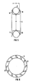
- a pushed-on sealing ring 3 is connected to the pipe 1 in order to seal a pipe 1 which can rotate about its longitudinal axis against a standing housing 2a.
- the sealing ring 3 rotates yourself with the pipe 1.
- a counter ring 5a is connected to the standing housing 2a via a flexible, tubular compensator 4a.
- the flexible compensator 4a consists of a gastight flexible fabric.
- a roller 6a is rotatably arranged on the circumferential surface of the counter ring 5a, the axis of rotation of which is directed perpendicular to the axis of the counter ring 5a.
- At least one first rail 7a is assigned to the roller 6a.
- the roller 6a is supported on the rail 7a.
- the first rail 7a is arranged obliquely to the tube axis and is firmly connected to the housing 2a.
- the roller 6a and the first rail 7a are arranged so that the counter ring 5a is positioned centered on the sealing ring 3.
- the roller 6a is assigned a second rail, which is referred to as a guide rail 8a. This runs parallel to the rail 7a and is also firmly connected to the housing 2a.
- the rail 7a and also the guide rail 8a which may be present are arranged obliquely to the pipe axis.
- the rails 7a and 8a have a slope from the housing 2a in the direction of the counter ring 5a.
- the angle to the horizontal or pipe axis is, for example, between 15 ° and 30 °. In particular 25 ° are chosen.
- the rail 7a forms an inclined plane for the roller 6a. A component of the weight of the roller 6a, the counter ring 5a and partially the compensator 4a presses the counter ring 5a against the sealing ring 3 in the construction shown.
- connection pressure is so great that additional connection means can be dispensed with.
- a further similar arrangement of the rail 7a and roller 6a and optionally the guide rail 8a is arranged on the opposite side of the compensator 4, which is not visible in FIG. 1, a further similar arrangement of the rail 7a and roller 6a and optionally the guide rail 8a is arranged.
- the mechanical seal can also make do with only one rail 7a on each side.
- a first rail 7b for the roller 6a can also be parallel to the pipe axis, i.e. run horizontally here.
- a second horizontal guide rail 8b can also be present parallel to the horizontally running rail 7b, which is also shown in FIG. 2.
- an additional means for pressing the counter ring 5a against the sealing ring 3 must be used.
- a known clip or spring clip 9 equipped with mechanical springs is suitable. Otherwise, the mechanical seal according to FIG. 2 is identical in construction to that according to FIG. 1.
- a rotatable tube 1 shown in dashed lines, is sealed against two standing housings 2a and 2b with a mechanical seal.
- a pushed-on sealing ring 3, which rotates with the pipe 1, is connected to the pipe 1.
- a first mating ring 5a is connected to the first housing 2a via a first flexible compensator 4a, the end face of which is assigned and facing an end face of the sealing ring 3.
- a second counter ring Sb is connected to the second housing 2b via a second flexible compensator 4b. The end face of this second counter ring 5b is assigned to the end face of the sealing ring 3 facing away from the first counter ring 5a and facing.
- a first roller 6a is arranged perpendicularly on the circumference of the first counter ring 5a and a second roller 6b is rotatably arranged on the circumference of the second counter ring 5b.
- the first roller 6a is supported at the bottom on a first horizontal rail 7b, which is arranged parallel to the tube axis outside the compensator 4a and is connected to the first housing 2a.
- the second roller 6b is supported at the bottom on a second horizontal rail 7c, which is connected to the second housing 2b.
- parallel guide rails 8b and 8c are assigned to the rails 7b and 7c.
- the two rails 7b and 7c can each extend from the first housing 2a to the second housing 2b, and they can be connected to the two housings 2a and 2b when a movement of the two housings 2a and 2b against each other caused by different thermal expansions of the Housing 2a and 2b can be caused, must not be expected.
- the distance between the two rails 7b and 7c can then be selected such that the first rail 7b forms a rail with the guide rail 8c of the second roller 6b.
- a third rail can be arranged at a suitable distance above the first rail 7b.
- rollers 6a and 6b When using horizontally running rails 7b, 7c and guide rails 8b, 8c, the rollers 6a and 6b only serve to hold the two counter rings 5a and 5b in a centered manner.
- U-shaped brackets 9 are provided for pressing the counter rings 5a and 5b onto the sealing ring 3.
- FIG 3 it is not visible that on the opposite side of the rollers 6a and 6b of the counter rings 5a and 5b and the compensators 4a and 4b, similar rollers 6a and 6b and similar rails 7b, 7c and optionally guide rails 8b, 8c are arranged.
- the first roller 6a is supported on an inclined first rail 7a.
- the first rail 7a has a slope directed towards the sealing ring 3.
- the second roller 6b is supported on a second inclined rail 7d, which also has a slope directed towards the sealing ring 3.
- the components of the weight forces of the rollers 6a and 6b are sufficient to press the two counter rings 5a and 5b against the sealing ring 3 from the opposite direction.
- each roller 6a and 6b can be assigned a guide rail 8a or 8d connected to the respective housing 2a or 2b.
- the rails 7a and 7d and the guide rails 8a and 8d each run inclined to one another. Further rollers 6a and 6b as well as further rails 7a and 7d and optionally further guide rails 8a and 8d are arranged on the opposite side of the counter rings 5a and 5b and the compensators 4a and 4b, which is not visible.
- the counter rings 5a and 5b are connected to the associated housings 2a and 2b via flexible compensators 4a and 4b, as in FIG.
- a roller 6 has a wheel flange 10 and 11 on both sides.
- the roller 6 runs on a lower rail 7 with a round cross-section. Lifting of the roller 6 from the rail 7 is prevented by a guide rail 8 with a round cross section above the roller 6.
- the flanges 10, 11 prevent the roller 6 from sliding off the rail 7 or from the rails 7 and 8. If sliding in only one direction is to be prevented, a one-sided flange 10 on the roller 6 is sufficient. So that there is little freedom of movement for the roller 6, the rolling diameter d of the roller 6 should be slightly smaller than the distance between the rail 7 and the guide rail 8. Likewise, the distance a between two flanges 10 and 11 of the roller 6 should be slightly larger than the diameter of the rail 7 and the guide rail 8. This gives the roller 6 a lateral range of motion.
- grooves 12 are arranged on a counter ring 5 on the side facing the sealing ring 3 in order to receive lubricant or lubricant, which enables a particularly good gas-tight seal.
- the grooves 12 run, for example, at an angle to the diameter of the counter ring 5. They do not touch the edge of the counter ring 5.
- FIG. 7 shows a joint 13 with which the rails 7a, 7d shown in FIGS. 1 and 4 can be connected to the housing 2a, 2b.
- the joint 13 according to FIG. 7 consists of a flat body 14 formed on the rail 7, which is connected with a bolt 15 as the axis of rotation to a rod-shaped component 20 formed on the housing 2.
- a gap 16 which has the shape of an arc of a circle surrounding the bolt 15.
- a locking screw 17 firmly connected to the component 20 engages in this gap 16.
- the inclination of the rail 7 can be adjusted continuously.
- the rail 7 is locked in each case by the locking screw 17.
- a guide rail 8 can optionally be firmly coupled to the rail 7 at the required distance.
- a sealing ring 3 which is connected to the tube 1, is assigned one or two fixed counter rings 5, 5a, 5b, which are connected to the housing 2a, 2b via compensators 4a , 4b are connected.
- a counter ring 5, 5a, 5b is held centered on the sealing ring 3 by rollers 6, 6a, 6b, which are arranged on its circumference and are supported on rails 7, 7a, 7b, 7c, 7d.
- the counter ring 5, 5a, 5b is pressed against the sealing ring 3 by a component of the weight of the roller 6, 6a, 6b, the counter ring 5, 5a, 5b and the compensator 4a, 4b.
- the roller 6, 6a, 6b is supported on a rail 7, 7a, 7d, which is connected to the housing 2a, 2b and has a slope in the direction of the sealing ring 5, 5a, 5b.
- the mechanical seal manages with little space and without expensive means.
Landscapes
- Engineering & Computer Science (AREA)
- General Engineering & Computer Science (AREA)
- Mechanical Engineering (AREA)
- Mechanical Sealing (AREA)
- Joints Allowing Movement (AREA)
- Sealing Devices (AREA)
- Laying Of Electric Cables Or Lines Outside (AREA)
- Joints With Sleeves (AREA)
- Joints With Pressure Members (AREA)
Applications Claiming Priority (2)
| Application Number | Priority Date | Filing Date | Title |
|---|---|---|---|
| EP89122577 | 1989-12-07 | ||
| EP89122577 | 1989-12-07 |
Publications (2)
| Publication Number | Publication Date |
|---|---|
| EP0431419A1 true EP0431419A1 (fr) | 1991-06-12 |
| EP0431419B1 EP0431419B1 (fr) | 1994-09-21 |
Family
ID=8202199
Family Applications (1)
| Application Number | Title | Priority Date | Filing Date |
|---|---|---|---|
| EP90122423A Expired - Lifetime EP0431419B1 (fr) | 1989-12-07 | 1990-11-23 | Garniture mécanique et dispositif pour assurer l'étanchéité d'un tuyau en rotation contre un bâti fixe |
Country Status (10)
| Country | Link |
|---|---|
| EP (1) | EP0431419B1 (fr) |
| AT (1) | ATE112027T1 (fr) |
| CZ (1) | CZ280255B6 (fr) |
| DE (1) | DE59007246D1 (fr) |
| DK (1) | DK0431419T3 (fr) |
| ES (1) | ES2060903T3 (fr) |
| HU (1) | HU206405B (fr) |
| PL (1) | PL164361B1 (fr) |
| RU (1) | RU2015434C1 (fr) |
| SK (1) | SK278409B6 (fr) |
Cited By (3)
| Publication number | Priority date | Publication date | Assignee | Title |
|---|---|---|---|---|
| WO1995007956A1 (fr) * | 1993-09-16 | 1995-03-23 | Siemens Aktiengesellschaft | Bague d'etancheite glissante pour creer une etancheite entre un tuyau chaud et un boitier |
| DE19619342A1 (de) * | 1996-05-14 | 1997-11-20 | Riedhammer Gmbh Co Kg | Einrichtung zum Abdichten von drehbaren Rohren gegen ein Gehäuse |
| DE19623577A1 (de) * | 1996-06-13 | 1998-01-02 | Krc Umwelttechnik Gmbh | Dichtung für Drehrohre |
Citations (4)
| Publication number | Priority date | Publication date | Assignee | Title |
|---|---|---|---|---|
| DE1192967B (de) * | 1961-08-26 | 1965-05-13 | Beteiligungs & Patentverw Gmbh | Abdichtung an Drehrohroefen |
| DE1475621A1 (de) * | 1964-09-30 | 1969-01-16 | J C Carter Company | Selbstreinigende Dichtung |
| EP0255662A2 (fr) * | 1986-08-04 | 1988-02-10 | Siemens Aktiengesellschaft | Joint d'étanchéité |
| EP0274090A2 (fr) * | 1986-12-23 | 1988-07-13 | Feodor Burgmann Dichtungswerke GmbH & Co. | Dispositif d'étanchéité |
-
1990
- 1990-11-23 EP EP90122423A patent/EP0431419B1/fr not_active Expired - Lifetime
- 1990-11-23 ES ES90122423T patent/ES2060903T3/es not_active Expired - Lifetime
- 1990-11-23 CZ CS905837A patent/CZ280255B6/cs not_active IP Right Cessation
- 1990-11-23 DK DK90122423.8T patent/DK0431419T3/da active
- 1990-11-23 AT AT90122423T patent/ATE112027T1/de not_active IP Right Cessation
- 1990-11-23 DE DE59007246T patent/DE59007246D1/de not_active Expired - Fee Related
- 1990-11-23 SK SK5837-90A patent/SK278409B6/sk unknown
- 1990-11-26 PL PL90287934A patent/PL164361B1/pl unknown
- 1990-12-06 RU SU904831778A patent/RU2015434C1/ru active
- 1990-12-06 HU HU908103A patent/HU206405B/hu not_active IP Right Cessation
Patent Citations (4)
| Publication number | Priority date | Publication date | Assignee | Title |
|---|---|---|---|---|
| DE1192967B (de) * | 1961-08-26 | 1965-05-13 | Beteiligungs & Patentverw Gmbh | Abdichtung an Drehrohroefen |
| DE1475621A1 (de) * | 1964-09-30 | 1969-01-16 | J C Carter Company | Selbstreinigende Dichtung |
| EP0255662A2 (fr) * | 1986-08-04 | 1988-02-10 | Siemens Aktiengesellschaft | Joint d'étanchéité |
| EP0274090A2 (fr) * | 1986-12-23 | 1988-07-13 | Feodor Burgmann Dichtungswerke GmbH & Co. | Dispositif d'étanchéité |
Cited By (6)
| Publication number | Priority date | Publication date | Assignee | Title |
|---|---|---|---|---|
| WO1995007956A1 (fr) * | 1993-09-16 | 1995-03-23 | Siemens Aktiengesellschaft | Bague d'etancheite glissante pour creer une etancheite entre un tuyau chaud et un boitier |
| DE19619342A1 (de) * | 1996-05-14 | 1997-11-20 | Riedhammer Gmbh Co Kg | Einrichtung zum Abdichten von drehbaren Rohren gegen ein Gehäuse |
| DE19619342C2 (de) * | 1996-05-14 | 2000-01-05 | Riedhammer Gmbh Co Kg | Einrichtung zum Abdichten eines drehbaren Rohres gegen ein Gehäuse |
| DE19623577A1 (de) * | 1996-06-13 | 1998-01-02 | Krc Umwelttechnik Gmbh | Dichtung für Drehrohre |
| DE19623577C2 (de) * | 1996-06-13 | 1998-04-30 | Krc Umwelttechnik Gmbh | Dichtung für Drehrohre |
| US6003874A (en) * | 1996-06-13 | 1999-12-21 | Noell-Krc Energie-Und Umwelttechnik Gmbh | Apparatus for sealing rotary tubes |
Also Published As
| Publication number | Publication date |
|---|---|
| SK278409B6 (en) | 1997-04-09 |
| ATE112027T1 (de) | 1994-10-15 |
| RU2015434C1 (ru) | 1994-06-30 |
| EP0431419B1 (fr) | 1994-09-21 |
| CS583790A3 (en) | 1992-02-19 |
| PL287934A1 (en) | 1991-07-15 |
| DK0431419T3 (da) | 1995-02-20 |
| HU206405B (en) | 1992-10-28 |
| DE59007246D1 (de) | 1994-10-27 |
| CZ280255B6 (cs) | 1995-12-13 |
| HUT55894A (en) | 1991-06-28 |
| PL164361B1 (pl) | 1994-07-29 |
| ES2060903T3 (es) | 1994-12-01 |
Similar Documents
| Publication | Publication Date | Title |
|---|---|---|
| DE602005003946T2 (de) | Stützvorrichtung für prägewalzen und verfahren zu deren austausch | |
| EP2931430B1 (fr) | Presse à rouleaux | |
| DE3990222B4 (de) | Raupenfahrwerk | |
| EP1203167B1 (fr) | Station a cylindres de roulement pour soutenir de fa on basculante un corps tubulaire rotatif | |
| EP0570696B2 (fr) | Tambour rotatif | |
| DE2417682A1 (de) | Symmetrisches synchronisiertes bandsteuerungs- und spannsystem und vorrichtung fuer kontinuierliches zwillingsbandmetallgiessen | |
| DE60028304T2 (de) | Walzenlagerung mit integrierten Bauteilen | |
| EP1048570A2 (fr) | Dispositif de transport pour une machine d'emballage | |
| DE19941306C1 (de) | Rollenkette | |
| EP0431419B1 (fr) | Garniture mécanique et dispositif pour assurer l'étanchéité d'un tuyau en rotation contre un bâti fixe | |
| EP4077174A1 (fr) | Chariot de transport pour un convoyeur distributeur et ensemble de raccordement pour fixer un chariot de transport à un moyen d'entraînement d'un convoyeur distributeur | |
| EP0712801A1 (fr) | Méthode et dispositif pour approcher un châssis pivotant bidirectionnellement d'un dispositif de changement de rouleaux de papier | |
| DE2743129C2 (de) | Vorrichtung zum Haltern und Versetzen einer Lanze | |
| DE2741835A1 (de) | Rakeleinrichtung | |
| DE19501028A1 (de) | Parallelführung zum senkrechten Bewegen von Nutzlasten | |
| EP0271880A2 (fr) | Support à colonne et bras articulé sur celle-ci | |
| EP0412356A1 (fr) | Chaîne de rame | |
| WO1999041174A1 (fr) | Systeme de cylindres contacteurs d'une enrouleuse | |
| DE2553556C3 (de) | Verstellvorrichtung an fotografischen Vergrößerungs- oder Reprogeräten | |
| WO2005058546A1 (fr) | Tete de rouleau de cylindrage pour vilebrequin a goupille d'arret | |
| DE10144974B4 (de) | Walzgerüst zum Walzen von stab- oder rohrförmigem Gut | |
| DE3906618C2 (de) | Führungsvorrichtung für die Einbaustücke von Arbeitswalzen eines Walzgerüstes | |
| EP0296407B1 (fr) | Dispositif pour déplacer axialement les supports des paliers de cylindres | |
| EP0484623B1 (fr) | Presse à forger | |
| DE1602070A1 (de) | Walzgutrollenfuehrung |
Legal Events
| Date | Code | Title | Description |
|---|---|---|---|
| PUAI | Public reference made under article 153(3) epc to a published international application that has entered the european phase |
Free format text: ORIGINAL CODE: 0009012 |
|
| 17P | Request for examination filed |
Effective date: 19901205 |
|
| AK | Designated contracting states |
Kind code of ref document: A1 Designated state(s): AT BE CH DE DK ES FR GB GR IT LI LU NL SE |
|
| 17Q | First examination report despatched |
Effective date: 19930305 |
|
| GRAA | (expected) grant |
Free format text: ORIGINAL CODE: 0009210 |
|
| AK | Designated contracting states |
Kind code of ref document: B1 Designated state(s): AT BE CH DE DK ES FR GB GR IT LI LU NL SE |
|
| PG25 | Lapsed in a contracting state [announced via postgrant information from national office to epo] |
Ref country code: GR Free format text: LAPSE BECAUSE OF FAILURE TO SUBMIT A TRANSLATION OF THE DESCRIPTION OR TO PAY THE FEE WITHIN THE PRESCRIBED TIME-LIMIT Effective date: 19940921 |
|
| REF | Corresponds to: |
Ref document number: 112027 Country of ref document: AT Date of ref document: 19941015 Kind code of ref document: T |
|
| REF | Corresponds to: |
Ref document number: 59007246 Country of ref document: DE Date of ref document: 19941027 |
|
| REG | Reference to a national code |
Ref country code: ES Ref legal event code: FG2A Ref document number: 2060903 Country of ref document: ES Kind code of ref document: T3 |
|
| GBT | Gb: translation of ep patent filed (gb section 77(6)(a)/1977) |
Effective date: 19941114 |
|
| ITF | It: translation for a ep patent filed |
Owner name: STUDIO JAUMANN |
|
| EAL | Se: european patent in force in sweden |
Ref document number: 90122423.8 |
|
| ET | Fr: translation filed | ||
| REG | Reference to a national code |
Ref country code: DK Ref legal event code: T3 |
|
| PLBE | No opposition filed within time limit |
Free format text: ORIGINAL CODE: 0009261 |
|
| STAA | Information on the status of an ep patent application or granted ep patent |
Free format text: STATUS: NO OPPOSITION FILED WITHIN TIME LIMIT |
|
| 26N | No opposition filed | ||
| REG | Reference to a national code |
Ref country code: GB Ref legal event code: IF02 |
|
| PGFP | Annual fee paid to national office [announced via postgrant information from national office to epo] |
Ref country code: AT Payment date: 20051019 Year of fee payment: 16 |
|
| PGFP | Annual fee paid to national office [announced via postgrant information from national office to epo] |
Ref country code: GB Payment date: 20051108 Year of fee payment: 16 Ref country code: SE Payment date: 20051108 Year of fee payment: 16 |
|
| PGFP | Annual fee paid to national office [announced via postgrant information from national office to epo] |
Ref country code: NL Payment date: 20051109 Year of fee payment: 16 |
|
| PGFP | Annual fee paid to national office [announced via postgrant information from national office to epo] |
Ref country code: DK Payment date: 20051110 Year of fee payment: 16 |
|
| PGFP | Annual fee paid to national office [announced via postgrant information from national office to epo] |
Ref country code: BE Payment date: 20051118 Year of fee payment: 16 |
|
| PGFP | Annual fee paid to national office [announced via postgrant information from national office to epo] |
Ref country code: FR Payment date: 20051122 Year of fee payment: 16 Ref country code: LU Payment date: 20051122 Year of fee payment: 16 |
|
| PGFP | Annual fee paid to national office [announced via postgrant information from national office to epo] |
Ref country code: ES Payment date: 20051214 Year of fee payment: 16 |
|
| PGFP | Annual fee paid to national office [announced via postgrant information from national office to epo] |
Ref country code: DE Payment date: 20060123 Year of fee payment: 16 |
|
| PGFP | Annual fee paid to national office [announced via postgrant information from national office to epo] |
Ref country code: CH Payment date: 20060206 Year of fee payment: 16 |
|
| REG | Reference to a national code |
Ref country code: CH Ref legal event code: PUE Owner name: MITSUI ENGINEERING & SHIPBUILDING CO., LTD. Free format text: SIEMENS AKTIENGESELLSCHAFT#WITTELSBACHERPLATZ 2#D-80333 MUENCHEN (DE) -TRANSFER TO- MITSUI ENGINEERING & SHIPBUILDING CO., LTD.#64, TSUKIJI 5-CHOME, CHUO-KU#TOKYO 104-8439 (JP) $ TAKUMA CO., LTD.#1-3-23 DOJIMAHAMA , KITA -KU#OSAKA 530-004 (JP) |
|
| REG | Reference to a national code |
Ref country code: GB Ref legal event code: 732E |
|
| REG | Reference to a national code |
Ref country code: FR Ref legal event code: TP |
|
| PG25 | Lapsed in a contracting state [announced via postgrant information from national office to epo] |
Ref country code: AT Free format text: LAPSE BECAUSE OF NON-PAYMENT OF DUE FEES Effective date: 20061123 |
|
| PG25 | Lapsed in a contracting state [announced via postgrant information from national office to epo] |
Ref country code: SE Free format text: LAPSE BECAUSE OF NON-PAYMENT OF DUE FEES Effective date: 20061124 |
|
| PG25 | Lapsed in a contracting state [announced via postgrant information from national office to epo] |
Ref country code: CH Free format text: LAPSE BECAUSE OF NON-PAYMENT OF DUE FEES Effective date: 20061130 Ref country code: LI Free format text: LAPSE BECAUSE OF NON-PAYMENT OF DUE FEES Effective date: 20061130 Ref country code: DK Free format text: LAPSE BECAUSE OF NON-PAYMENT OF DUE FEES Effective date: 20061130 Ref country code: BE Free format text: LAPSE BECAUSE OF NON-PAYMENT OF DUE FEES Effective date: 20061130 |
|
| PGFP | Annual fee paid to national office [announced via postgrant information from national office to epo] |
Ref country code: IT Payment date: 20061130 Year of fee payment: 17 |
|
| PG25 | Lapsed in a contracting state [announced via postgrant information from national office to epo] |
Ref country code: NL Free format text: LAPSE BECAUSE OF NON-PAYMENT OF DUE FEES Effective date: 20070601 Ref country code: DE Free format text: LAPSE BECAUSE OF NON-PAYMENT OF DUE FEES Effective date: 20070601 |
|
| REG | Reference to a national code |
Ref country code: DK Ref legal event code: EBP |
|
| REG | Reference to a national code |
Ref country code: CH Ref legal event code: PL |
|
| EUG | Se: european patent has lapsed | ||
| GBPC | Gb: european patent ceased through non-payment of renewal fee |
Effective date: 20061123 |
|
| NLV4 | Nl: lapsed or anulled due to non-payment of the annual fee |
Effective date: 20070601 |
|
| REG | Reference to a national code |
Ref country code: FR Ref legal event code: ST Effective date: 20070731 |
|
| PG25 | Lapsed in a contracting state [announced via postgrant information from national office to epo] |
Ref country code: GB Free format text: LAPSE BECAUSE OF NON-PAYMENT OF DUE FEES Effective date: 20061123 |
|
| BERE | Be: lapsed |
Owner name: *SIEMENS A.G. Effective date: 20061130 |
|
| REG | Reference to a national code |
Ref country code: ES Ref legal event code: FD2A Effective date: 20061124 |
|
| PG25 | Lapsed in a contracting state [announced via postgrant information from national office to epo] |
Ref country code: FR Free format text: LAPSE BECAUSE OF NON-PAYMENT OF DUE FEES Effective date: 20061130 Ref country code: ES Free format text: LAPSE BECAUSE OF NON-PAYMENT OF DUE FEES Effective date: 20061124 |
|
| PG25 | Lapsed in a contracting state [announced via postgrant information from national office to epo] |
Ref country code: LU Free format text: LAPSE BECAUSE OF NON-PAYMENT OF DUE FEES Effective date: 20061123 |
|
| PG25 | Lapsed in a contracting state [announced via postgrant information from national office to epo] |
Ref country code: IT Free format text: LAPSE BECAUSE OF NON-PAYMENT OF DUE FEES Effective date: 20071123 |