EP0431419A1 - Mechanical seal and device for sealing a rotating pipe against a fixed casing - Google Patents
Mechanical seal and device for sealing a rotating pipe against a fixed casing Download PDFInfo
- Publication number
- EP0431419A1 EP0431419A1 EP90122423A EP90122423A EP0431419A1 EP 0431419 A1 EP0431419 A1 EP 0431419A1 EP 90122423 A EP90122423 A EP 90122423A EP 90122423 A EP90122423 A EP 90122423A EP 0431419 A1 EP0431419 A1 EP 0431419A1
- Authority
- EP
- European Patent Office
- Prior art keywords
- rail
- ring
- roller
- mechanical seal
- counter
- Prior art date
- Legal status (The legal status is an assumption and is not a legal conclusion. Google has not performed a legal analysis and makes no representation as to the accuracy of the status listed.)
- Granted
Links
Images


Classifications
-
- F—MECHANICAL ENGINEERING; LIGHTING; HEATING; WEAPONS; BLASTING
- F27—FURNACES; KILNS; OVENS; RETORTS
- F27D—DETAILS OR ACCESSORIES OF FURNACES, KILNS, OVENS, OR RETORTS, IN SO FAR AS THEY ARE OF KINDS OCCURRING IN MORE THAN ONE KIND OF FURNACE
- F27D99/00—Subject matter not provided for in other groups of this subclass
- F27D99/0073—Seals
-
- F—MECHANICAL ENGINEERING; LIGHTING; HEATING; WEAPONS; BLASTING
- F16—ENGINEERING ELEMENTS AND UNITS; GENERAL MEASURES FOR PRODUCING AND MAINTAINING EFFECTIVE FUNCTIONING OF MACHINES OR INSTALLATIONS; THERMAL INSULATION IN GENERAL
- F16J—PISTONS; CYLINDERS; SEALINGS
- F16J15/00—Sealings
- F16J15/16—Sealings between relatively-moving surfaces
- F16J15/34—Sealings between relatively-moving surfaces with slip-ring pressed against a more or less radial face on one member
- F16J15/36—Sealings between relatively-moving surfaces with slip-ring pressed against a more or less radial face on one member connected by a diaphragm or bellow to the other member
-
- F—MECHANICAL ENGINEERING; LIGHTING; HEATING; WEAPONS; BLASTING
- F16—ENGINEERING ELEMENTS AND UNITS; GENERAL MEASURES FOR PRODUCING AND MAINTAINING EFFECTIVE FUNCTIONING OF MACHINES OR INSTALLATIONS; THERMAL INSULATION IN GENERAL
- F16L—PIPES; JOINTS OR FITTINGS FOR PIPES; SUPPORTS FOR PIPES, CABLES OR PROTECTIVE TUBING; MEANS FOR THERMAL INSULATION IN GENERAL
- F16L27/00—Adjustable joints, Joints allowing movement
- F16L27/12—Adjustable joints, Joints allowing movement allowing substantial longitudinal adjustment or movement
- F16L27/125—Adjustable joints, Joints allowing movement allowing substantial longitudinal adjustment or movement having longitudinal and rotary movement
-
- F—MECHANICAL ENGINEERING; LIGHTING; HEATING; WEAPONS; BLASTING
- F27—FURNACES; KILNS; OVENS; RETORTS
- F27B—FURNACES, KILNS, OVENS, OR RETORTS IN GENERAL; OPEN SINTERING OR LIKE APPARATUS
- F27B7/00—Rotary-drum furnaces, i.e. horizontal or slightly inclined
- F27B7/20—Details, accessories, or equipment peculiar to rotary-drum furnaces
- F27B7/22—Rotary drums; Supports therefor
- F27B7/24—Seals between rotary and stationary parts
-
- F—MECHANICAL ENGINEERING; LIGHTING; HEATING; WEAPONS; BLASTING
- F27—FURNACES; KILNS; OVENS; RETORTS
- F27D—DETAILS OR ACCESSORIES OF FURNACES, KILNS, OVENS, OR RETORTS, IN SO FAR AS THEY ARE OF KINDS OCCURRING IN MORE THAN ONE KIND OF FURNACE
- F27D17/00—Arrangements for using waste heat; Arrangements for using, or disposing of, waste gases
- F27D17/001—Extraction of waste gases, collection of fumes and hoods used therefor
- F27D17/002—Details of the installations, e.g. fume conduits or seals
Definitions
- the invention relates to a mechanical seal for sealing a rotatable tube against a standing housing.
- Such mechanical seals and suitable methods for sealing a rotatable tube against a standing housing are known.
- a compensator is used which consists of a flexible material, for example an impregnated fabric. This compensator is necessary so that different thermal expansions of the pipe and the housing can be compensated and that no damage to one of the components can occur. Different thermal expansions of the tube and the housing are to be expected especially if there is a temperature change in the tube due to combustion.
- the tube assigned to a housing can be, for example, a smoldering drum known from EP-A-0 302 310. There is a gas space in the upright housing, which must be sealed by the mechanical seal against the interior of the tube, in which charring of waste takes place.
- the smoldering drum is a component of a system for carrying out a smoldering-burning process.
- the positioned counter ring must also be pressed against the sealing ring using suitable means. This is the only way to achieve a gas-tight seal. So far, mechanical, pneumatic or hydraulic means have been used for this. Common means are brackets that enclose the sealing ring and counter ring on the circumference. The brackets are equipped with mechanical springs, pneumatic cylinders or hydraulic cylinders that press the sealing ring and counter ring against each other.
- the usual supporting structures or supporting devices for the counter ring and compensator require complex monitoring, since they have to be tracked in the event of heat-related displacements of the counter ring. Care must be taken that the mating ring is always kept stable in the carrying device and does not slip off the carrying device.
- the usual means of pressing the counter ring onto the sealing ring also require constant monitoring. Care must be taken that the contact pressure of the mechanical spring, the pneumatic cylinder or the hydraulic cylinder is always sufficiently large.
- the invention has for its object to provide a mechanical seal in which the counter ring is always positioned sufficiently centered on the sealing ring without the position of a support device having to be monitored.
- a mechanical seal should also be specified, in which no means are required to press the counter ring onto the sealing ring, which means that frequent monitoring is required.
- a mechanical seal for sealing a rotatable tube against a stationary housing with a sealing ring rotatable with the pipe and connected to the pipe and coaxial with the pipe, with a mating ring connected to the housing via a flexible compensator for compensating changes in length of the tube, which can be pressed with an end sealing surface against an end sealing surface of the sealing ring for sealing the housing against the tube, with at least one roller arranged to support the counter ring and the compensator on the peripheral surface of the counter ring, the axis of rotation of which is perpendicular to the peripheral surface of the counter ring, and with at least one rail which is fastened to the stationary housing and on which the at least one roller is supported and can be moved in a rolling manner.
- the counter ring and the compensator are kept space-saving. In addition, there is always an optimal support point without tracking a hoist.
- an end sealing surface of one of two mating rings can be pressed onto the sealing ring on two opposite sealing faces.
- the pipe is sealed against two housings.
- Each of the two mating rings is connected to its housing via its own compensator. Rollers are also arranged on each counter ring, which can move on rails attached to the housing.
- the mechanical seal for sealing a rotatable tube against two standing housings thus corresponds to a mirror-symmetrical doubling of the mechanical seal for a tube and a housing.
- the single sealing ring of the single tube is joined on both sides by mating rings which are connected to the housings via compensators.
- Such a mechanical seal can advantageously be used if two gas flows are to be separated from one another.
- Combustion in particular the smoldering method mentioned, can be a gas to be supplied and a gas to be removed.
- the rails are arranged inclined against the direction of the axis of the rotatable sealing ring with a gradient from the housing to the sealing ring. They form an inclined plane for the roles.
- a component of gravity directed towards the sealing ring always acts on the rollers. With this force the counter ring is pressed against the sealing ring.
- the gravity component is sufficient to press the counter ring gas-tight onto the sealing ring.
- another rail is arranged as a guide rail such that the roller is guided between the two rails.
- the roller in connection with the two rails forms an anti-rotation device for the counter ring.
- the counter ring can therefore not be rotated about its axis by external forces. This also prevents the compensator from being damaged or even destroyed by such a movement. Turning the counter ring could cause the compensator to tear.
- the roller has, for example, a flange on one or both sides for guidance on the rail or on the guide rail.
- the role can thus be constructed similar to a railway wheel. It can also have two wheel flanges and then have the shape of a spindle wheel.
- a roller provided with a flange cannot be pushed away from the rail in the event of any radial displacements of the counter ring. If only one wheel flange is used, the roller is held radially to the counter ring in one direction. When using two flanges, it is also held in the opposite direction. This has the advantage that the roller cannot be lifted off or removed from the rail not only during rotary movements of the counter ring, but also during radial lateral movements of the counter ring.
- the roller has a wheel flange on both sides, the distance of the wheel flanges from one another and thus also the width of the running surface of the roller being slight is greater than the width of the rail or the guide rail. In this way, there is little play for radial movements of the counter ring.
- the distance between the rail and the guide rail is slightly larger than the rolling diameter of the roll. This allows slight rotary movements of the counter ring. Due to the play of the roller between the rails, there is no tension in the material. Damage to the compensator from such slight rotary movements is not expected. Despite the clearance between the rails, the roller is held because the total diameter of the roller with flange is larger than the distance between the rail and the guide rail.
- the mating ring in the side that comes into contact with the sealing ring has grooves for receiving lubricant or lubricant.
- lubricants or lubricants on the one hand a gas-tight seal of the sealing ring and mating ring against one another and on the other hand an easy sliding of the rings on one another is ensured.
- the grooves on the counter ring are evenly distributed and arranged at an angle to the diameter of the counter ring. This ensures an optimal distribution of the lubricant or lubricant.
- the rails are connected to the stationary housing via a hinge, whereby their angle of inclination against the axis of the rotatable sealing ring is variable.
- This has the advantage that the contact pressure with which the counter ring is pressed against the sealing ring can also be changed.
- the contact pressure can advantageously be adapted to the respective requirements by changing the angle of inclination.
- the angle of inclination can even be changed in the operating state, that is to say while the pipe is rotating.
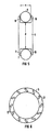
- a pushed-on sealing ring 3 is connected to the pipe 1 in order to seal a pipe 1 which can rotate about its longitudinal axis against a standing housing 2a.
- the sealing ring 3 rotates yourself with the pipe 1.
- a counter ring 5a is connected to the standing housing 2a via a flexible, tubular compensator 4a.
- the flexible compensator 4a consists of a gastight flexible fabric.
- a roller 6a is rotatably arranged on the circumferential surface of the counter ring 5a, the axis of rotation of which is directed perpendicular to the axis of the counter ring 5a.
- At least one first rail 7a is assigned to the roller 6a.
- the roller 6a is supported on the rail 7a.
- the first rail 7a is arranged obliquely to the tube axis and is firmly connected to the housing 2a.
- the roller 6a and the first rail 7a are arranged so that the counter ring 5a is positioned centered on the sealing ring 3.
- the roller 6a is assigned a second rail, which is referred to as a guide rail 8a. This runs parallel to the rail 7a and is also firmly connected to the housing 2a.
- the rail 7a and also the guide rail 8a which may be present are arranged obliquely to the pipe axis.
- the rails 7a and 8a have a slope from the housing 2a in the direction of the counter ring 5a.
- the angle to the horizontal or pipe axis is, for example, between 15 ° and 30 °. In particular 25 ° are chosen.
- the rail 7a forms an inclined plane for the roller 6a. A component of the weight of the roller 6a, the counter ring 5a and partially the compensator 4a presses the counter ring 5a against the sealing ring 3 in the construction shown.
- connection pressure is so great that additional connection means can be dispensed with.
- a further similar arrangement of the rail 7a and roller 6a and optionally the guide rail 8a is arranged on the opposite side of the compensator 4, which is not visible in FIG. 1, a further similar arrangement of the rail 7a and roller 6a and optionally the guide rail 8a is arranged.
- the mechanical seal can also make do with only one rail 7a on each side.
- a first rail 7b for the roller 6a can also be parallel to the pipe axis, i.e. run horizontally here.
- a second horizontal guide rail 8b can also be present parallel to the horizontally running rail 7b, which is also shown in FIG. 2.
- an additional means for pressing the counter ring 5a against the sealing ring 3 must be used.
- a known clip or spring clip 9 equipped with mechanical springs is suitable. Otherwise, the mechanical seal according to FIG. 2 is identical in construction to that according to FIG. 1.
- a rotatable tube 1 shown in dashed lines, is sealed against two standing housings 2a and 2b with a mechanical seal.
- a pushed-on sealing ring 3, which rotates with the pipe 1, is connected to the pipe 1.
- a first mating ring 5a is connected to the first housing 2a via a first flexible compensator 4a, the end face of which is assigned and facing an end face of the sealing ring 3.
- a second counter ring Sb is connected to the second housing 2b via a second flexible compensator 4b. The end face of this second counter ring 5b is assigned to the end face of the sealing ring 3 facing away from the first counter ring 5a and facing.
- a first roller 6a is arranged perpendicularly on the circumference of the first counter ring 5a and a second roller 6b is rotatably arranged on the circumference of the second counter ring 5b.
- the first roller 6a is supported at the bottom on a first horizontal rail 7b, which is arranged parallel to the tube axis outside the compensator 4a and is connected to the first housing 2a.
- the second roller 6b is supported at the bottom on a second horizontal rail 7c, which is connected to the second housing 2b.
- parallel guide rails 8b and 8c are assigned to the rails 7b and 7c.
- the two rails 7b and 7c can each extend from the first housing 2a to the second housing 2b, and they can be connected to the two housings 2a and 2b when a movement of the two housings 2a and 2b against each other caused by different thermal expansions of the Housing 2a and 2b can be caused, must not be expected.
- the distance between the two rails 7b and 7c can then be selected such that the first rail 7b forms a rail with the guide rail 8c of the second roller 6b.
- a third rail can be arranged at a suitable distance above the first rail 7b.
- rollers 6a and 6b When using horizontally running rails 7b, 7c and guide rails 8b, 8c, the rollers 6a and 6b only serve to hold the two counter rings 5a and 5b in a centered manner.
- U-shaped brackets 9 are provided for pressing the counter rings 5a and 5b onto the sealing ring 3.
- FIG 3 it is not visible that on the opposite side of the rollers 6a and 6b of the counter rings 5a and 5b and the compensators 4a and 4b, similar rollers 6a and 6b and similar rails 7b, 7c and optionally guide rails 8b, 8c are arranged.
- the first roller 6a is supported on an inclined first rail 7a.
- the first rail 7a has a slope directed towards the sealing ring 3.
- the second roller 6b is supported on a second inclined rail 7d, which also has a slope directed towards the sealing ring 3.
- the components of the weight forces of the rollers 6a and 6b are sufficient to press the two counter rings 5a and 5b against the sealing ring 3 from the opposite direction.
- each roller 6a and 6b can be assigned a guide rail 8a or 8d connected to the respective housing 2a or 2b.
- the rails 7a and 7d and the guide rails 8a and 8d each run inclined to one another. Further rollers 6a and 6b as well as further rails 7a and 7d and optionally further guide rails 8a and 8d are arranged on the opposite side of the counter rings 5a and 5b and the compensators 4a and 4b, which is not visible.
- the counter rings 5a and 5b are connected to the associated housings 2a and 2b via flexible compensators 4a and 4b, as in FIG.
- a roller 6 has a wheel flange 10 and 11 on both sides.
- the roller 6 runs on a lower rail 7 with a round cross-section. Lifting of the roller 6 from the rail 7 is prevented by a guide rail 8 with a round cross section above the roller 6.
- the flanges 10, 11 prevent the roller 6 from sliding off the rail 7 or from the rails 7 and 8. If sliding in only one direction is to be prevented, a one-sided flange 10 on the roller 6 is sufficient. So that there is little freedom of movement for the roller 6, the rolling diameter d of the roller 6 should be slightly smaller than the distance between the rail 7 and the guide rail 8. Likewise, the distance a between two flanges 10 and 11 of the roller 6 should be slightly larger than the diameter of the rail 7 and the guide rail 8. This gives the roller 6 a lateral range of motion.
- grooves 12 are arranged on a counter ring 5 on the side facing the sealing ring 3 in order to receive lubricant or lubricant, which enables a particularly good gas-tight seal.
- the grooves 12 run, for example, at an angle to the diameter of the counter ring 5. They do not touch the edge of the counter ring 5.
- FIG. 7 shows a joint 13 with which the rails 7a, 7d shown in FIGS. 1 and 4 can be connected to the housing 2a, 2b.
- the joint 13 according to FIG. 7 consists of a flat body 14 formed on the rail 7, which is connected with a bolt 15 as the axis of rotation to a rod-shaped component 20 formed on the housing 2.
- a gap 16 which has the shape of an arc of a circle surrounding the bolt 15.
- a locking screw 17 firmly connected to the component 20 engages in this gap 16.
- the inclination of the rail 7 can be adjusted continuously.
- the rail 7 is locked in each case by the locking screw 17.
- a guide rail 8 can optionally be firmly coupled to the rail 7 at the required distance.
- a sealing ring 3 which is connected to the tube 1, is assigned one or two fixed counter rings 5, 5a, 5b, which are connected to the housing 2a, 2b via compensators 4a , 4b are connected.
- a counter ring 5, 5a, 5b is held centered on the sealing ring 3 by rollers 6, 6a, 6b, which are arranged on its circumference and are supported on rails 7, 7a, 7b, 7c, 7d.
- the counter ring 5, 5a, 5b is pressed against the sealing ring 3 by a component of the weight of the roller 6, 6a, 6b, the counter ring 5, 5a, 5b and the compensator 4a, 4b.
- the roller 6, 6a, 6b is supported on a rail 7, 7a, 7d, which is connected to the housing 2a, 2b and has a slope in the direction of the sealing ring 5, 5a, 5b.
- the mechanical seal manages with little space and without expensive means.
Abstract
Description
Die Erfindung betrifft eine Gleitringdichtung zum Abdichten eines drehbaren Rohres gegen ein stehendes Gehäuse.The invention relates to a mechanical seal for sealing a rotatable tube against a standing housing.
Derartige Gleitringdichtungen und geeignete Verfahren zum Abdichten eines drehbaren Rohres gegen ein stehendes Gehäuse sind bekannt. Dabei wird in der Regel ein Kompensator eingesetzt, der aus einem flexiblen Material, beispielsweise aus einem impregnierten Gewebe, besteht. Dieser Kompensator ist notwendig, damit unterschiedliche Wärmedehnungen des Rohres und des Gehäuses kompensiert werden können und es nicht zu Beschädigungen an einem der Bauteile kommen kann. Unterschiedliche Wärmedehnungen von Rohr und Gehäuse sind besonders dann zu erwarten, wenn in dem Rohr eine Temperaturänderung infolge einer Verbrennung stattfindet. Das einem Gehäuse zugeordnete Rohr kann beispielsweise eine aus der EP-A-0 302 310 bekannte Schweltrommel sein. Dabei befindet sich im stehenden Gehäuse ein Gasraum, der durch die Gleitringdichtung gegen den Innenraum des Rohres, in dem eine Verschwelung von Abfall stattfindet, abgedichtet sein muß. Die Schweltrommel ist ein Bestandteil einer Anlage zur Durchführung eines Schwel-Brenn-Verfahrens.Such mechanical seals and suitable methods for sealing a rotatable tube against a standing housing are known. As a rule, a compensator is used which consists of a flexible material, for example an impregnated fabric. This compensator is necessary so that different thermal expansions of the pipe and the housing can be compensated and that no damage to one of the components can occur. Different thermal expansions of the tube and the housing are to be expected especially if there is a temperature change in the tube due to combustion. The tube assigned to a housing can be, for example, a smoldering drum known from EP-A-0 302 310. There is a gas space in the upright housing, which must be sealed by the mechanical seal against the interior of the tube, in which charring of waste takes place. The smoldering drum is a component of a system for carrying out a smoldering-burning process.
Da der Gegenring bei bekannten Gleitringdichtungen nur über den flexiblen Kompensator mit dem Gehäuse verbunden ist, der keine feste Verbindung darstellt, ist es erforderlich, den Gegenring und den Kompensator mit einem geeigneten Mittel in der gewünschten Lage zu halten. Dazu sind bisher verschiedenartige Tragkonstruktionen eingesetzt worden. Beispielsweise ist über der Anlage, die Gehäuse und Rohr umfaßt, ein Galgen angeordnet, auf dessen Ausleger eine Laufkatze verschiebbar positioniert ist. Der Gegenring ist dann mit Seilen oder Ketten an dieser Laufkatze aufgehängt. Es ist auch möglich, den Gegenring durch eine auf dem Boden des Raumes, in dem sich die Anlage befindet, beweglich angeordnete Konstruktion zu unterstützen.Since the counter ring in known mechanical seals is only connected to the housing via the flexible compensator, which is not a fixed connection, it is necessary to hold the counter ring and the compensator in the desired position with a suitable means. So far, various types of support structures have been used. For example, a gallows is arranged above the system, which comprises the housing and the pipe, on the boom of which a trolley can be moved is positioned. The counter ring is then suspended from this trolley with ropes or chains. It is also possible to support the counter ring by means of a construction which is movably arranged on the floor of the room in which the system is located.
Der positionierte Gegenring muß außerdem mit geeigneten Mitteln gegen den Dichtring gepreßt werden. Erst dadurch ist ein gasdichter Verschluß möglich. Bisher wurden dazu mechanische, pneumatische oder hydraulische Mittel eingesetzt. Übliche Mittel sind Klammern, die Dichtring und Gegenring am Umfang umfassen. Die Klammern sind mit mechanischen Federn, mit Pneumatikzylindern oder mit Hydraulikzylindern ausgestattet, die Dichtring und Gegenring gegeneinander pressen.The positioned counter ring must also be pressed against the sealing ring using suitable means. This is the only way to achieve a gas-tight seal. So far, mechanical, pneumatic or hydraulic means have been used for this. Common means are brackets that enclose the sealing ring and counter ring on the circumference. The brackets are equipped with mechanical springs, pneumatic cylinders or hydraulic cylinders that press the sealing ring and counter ring against each other.
Die üblichen Tragkonstruktionen oder Tragvorrichtungen für Gegenring und Kompensator erfordern eine aufwendige Überwachung, da sie bei wärmebedingten Verschiebungen des Gegenringes nachgeführt werden müssen. Es muß darauf geachtet werden, daß der Gegenring in der Tragvorrichtung stets stabil gehalten wird und nicht von der Tragvorrichtung abrutscht. Die üblichen Mittel zum Anpressen des Gegenringes an den Dichtring bedürfen ebenfalls einer ständigen Überwachung. Es muß darauf geachtet werden, daß die Anspreßkraft der mechanischen Feder, des Pneumatikzylinders oder des Hydraulikzylinders stets ausreichend groß ist.The usual supporting structures or supporting devices for the counter ring and compensator require complex monitoring, since they have to be tracked in the event of heat-related displacements of the counter ring. Care must be taken that the mating ring is always kept stable in the carrying device and does not slip off the carrying device. The usual means of pressing the counter ring onto the sealing ring also require constant monitoring. Care must be taken that the contact pressure of the mechanical spring, the pneumatic cylinder or the hydraulic cylinder is always sufficiently large.
Der Erfindung liegt die Aufgabe zugrunde, eine Gleitringdichtung anzugeben, bei der der Gegenring auf dem Dichtring stets ausreichend zentriert positioniert ist, ohne daß die Position einer Tragvorrichtung überwacht werden muß. Darüberhinaus soll auch eine Gleitringdichtung angegeben werden, bei der zum Anpressen des Gegenringes an den Dichtring keine Mittel erforderlich sind, die einer häufigen Überwachung bedürfen.The invention has for its object to provide a mechanical seal in which the counter ring is always positioned sufficiently centered on the sealing ring without the position of a support device having to be monitored. In addition, a mechanical seal should also be specified, in which no means are required to press the counter ring onto the sealing ring, which means that frequent monitoring is required.
Die Aufgabe wird gemäß der Erfindung dadurch gelöst, daß eine Gleitringdichtung vorgesehen ist, zum Abdichten eines drehbaren Rohres gegen ein stehendes Gehäuse
mit einem mit dem Rohr verbundenen koaxial zum Rohr angeordneten mit dem Rohr drehbaren Dichtring,
mit einem mit dem Gehäuse über einen flexiblen Kompensator zum Kompensieren von Längenänderungen des Rohres verbundenen Gegenring, der mit einer stirnseitigen Dichtfläche an eine stirnseitige Dichtfläche des Dichtringes zum Abdichten des Gehäuses gegen das Rohr anpreßbar ist,
mit mindestens einer zum Tragen des Gegenringes und des Kompensators an der Umfangsfläche des Gegenringes angeordneten Rolle, deren Drehachse senkrecht auf der Umfangsfläche des Gegenringes steht,
und mit mindestens einer Schiene, die am stehenden Gehäuse befestigt ist und auf der die mindestens eine Rolle abgestützt und rollend verschiebbar ist.The object is achieved according to the invention in that a mechanical seal is provided for sealing a rotatable tube against a stationary housing
with a sealing ring rotatable with the pipe and connected to the pipe and coaxial with the pipe,
with a mating ring connected to the housing via a flexible compensator for compensating changes in length of the tube, which can be pressed with an end sealing surface against an end sealing surface of the sealing ring for sealing the housing against the tube,
with at least one roller arranged to support the counter ring and the compensator on the peripheral surface of the counter ring, the axis of rotation of which is perpendicular to the peripheral surface of the counter ring,
and with at least one rail which is fastened to the stationary housing and on which the at least one roller is supported and can be moved in a rolling manner.
Damit wird der Vorteil erzielt, daß der Gegenring und der Kompensator platzsparend gehalten werden. Darüberhinaus ist ein Nachführen einer Tragvorrichtung nicht erforderlich. Bei einer möglichen Wärmedehnung des Rohres, was eine Verschiebung des Dichtringes in Achsrichtung zur Folge hat, wird der an den Dichtring angepresste Gegenring mitgenommen. Dabei bewegen sich die Rollen auf den Schienen. Bedingt durch das Rollen-Schienen-System finden die Rollen in jeder Position eine gleich gute Abstützung. Ein aufwendiges Nachführen eines Hebezeuges nach einer wärmebedingten axialen Verschiebung des Dichtringes und des Gegenringes ist also nicht erforderlich. Damit entfallen auch für eine solche Nachführung sonst notwendige motorgetriebene Geräte.This has the advantage that the counter ring and the compensator are kept space-saving. In addition, tracking of a carrying device is not necessary. In the event of a possible thermal expansion of the tube, which results in a displacement of the sealing ring in the axial direction, the counter ring pressed onto the sealing ring is taken along. The rollers move on the rails. Due to the roller-rail system, the rollers are equally well supported in every position. A complex tracking of a hoist after a thermal axial displacement of the sealing ring and the counter ring is therefore not necessary. This also eliminates the need for motor-driven devices that are necessary for such tracking.
Der Gegenring und der Kompensator werden platzsparend gehalten. Außerdem ist ohne Nachführung eines Hebezeuges stets ein optimaler Unterstützungspunkt gegeben.The counter ring and the compensator are kept space-saving. In addition, there is always an optimal support point without tracking a hoist.
Beispielsweise ist an den Dichtring an zwei gegenüberliegende stirnseitige Dichtflächen jeweils eine stirnseitige Dichtfläche eines von zwei Gegenringen anpreßbar. Auf diese Weise ist das Rohr gegen zwei Gehäuse abzudichten. Dabei ist jeder der beiden Gegenringe über einen eigenen Kompensator mit seinem Gehäuse verbunden. Auch sind an jedem Gegenring Rollen angeordnet, die sich auf am Gehäuse befestigten Schienen bewegen können. Die Gleitringdichtung zum Abdichten eines drehbaren Rohres gegen zwei stehende Gehäuse entspricht also einer spiegelsymmetrischen Verdopplung der Gleitringdichtung für ein Rohr und ein Gehäuse. An den einzigen Dichtring des einzigen Rohres schließen sich dabei beidseitig Gegenringe an, die über Kompensatoren mit den Gehäusen verbunden sind.For example, an end sealing surface of one of two mating rings can be pressed onto the sealing ring on two opposite sealing faces. In this way, the pipe is sealed against two housings. Each of the two mating rings is connected to its housing via its own compensator. Rollers are also arranged on each counter ring, which can move on rails attached to the housing. The mechanical seal for sealing a rotatable tube against two standing housings thus corresponds to a mirror-symmetrical doubling of the mechanical seal for a tube and a housing. The single sealing ring of the single tube is joined on both sides by mating rings which are connected to the housings via compensators.
Eine solche Gleitringdichtung ist vorteilhaft einsetzbar, wenn zwei Gasströme voneinander zu trennen sind. Dabei kann es sich bei einer Verbrennung, insbesondere bei dem erwähnten Schwel-Brenn-Verfahren, um ein zuzuführendes Gas und um ein abzuführendes Gas handeln.Such a mechanical seal can advantageously be used if two gas flows are to be separated from one another. Combustion, in particular the smoldering method mentioned, can be a gas to be supplied and a gas to be removed.
Beispielsweise sind die Schienen gegen die Richtung der Achse des drehbaren Dichtringes mit einem Gefälle vom Gehäuse zum Dichtring hin geneigt angeordnet. Sie bilden für die Rollen eine schiefe Ebene. Dadurch bedingt greift an die Rollen stets eine auf den Dichtring hin gerichtete Komponente der Schwerkraft an. Mit dieser Kraft wird der Gegenring gegen den Dichtring gedrückt. Bei geeignetem Gefälle der Schienen, es wird beispielsweise eine Neigung von 15° bis 40°, insbesondere von 25°, gegen die Horizontale gewählt, reicht die Schwerkraftkomponente aus, um den Gegenring gasdicht an den Dichtring anzupressen.For example, the rails are arranged inclined against the direction of the axis of the rotatable sealing ring with a gradient from the housing to the sealing ring. They form an inclined plane for the roles. As a result, a component of gravity directed towards the sealing ring always acts on the rollers. With this force the counter ring is pressed against the sealing ring. With a suitable slope of the rails, for example an inclination of 15 ° to 40 °, in particular 25 °, relative to the horizontal is selected, the gravity component is sufficient to press the counter ring gas-tight onto the sealing ring.
Mit diesem Mittel zum Anpressen des Gegenringes an den Dichtring wird der Vorteil erzielt, daß stets eine ausreichend große Anpreßkraft gegeben ist, ohne daß Anpreßmittel, wie mechanische Federn, pneumatische oder hydraulische Zylinder erforderlich wären, deren Funktion laufend überwacht werden müßte. Es sind auch keine zusätzlichen Geräte, wie beispielsweise Kompressoren erforderlich, die zum Betrieb von Hydraulikzylindern benötigt würden.With this means for pressing the counter ring onto the sealing ring, the advantage is achieved that there is always a sufficiently large contact pressure without contact means such as mechanical springs, pneumatic or hydraulic cylinders would be required, the function of which would have to be monitored continuously. There is also no need for additional devices, such as compressors, which would be required to operate hydraulic cylinders.
Beispielsweise ist parallel zu einer Schiene, auf der eine Rolle zu bewegen ist, eine weitere Schiene als Führungsschiene derart angeordnet, daß die Rolle zwischen beiden Schienen geführt ist. Die Rolle in Verbindung mit den beiden Schienen bildet eine Verdrehsicherung für den Gegenring. Der Gegenring kann folglich nicht durch von außen einwirkende Kräfte um seine Achse gedreht werden. Damit ist auch ausgeschlossen, daß der Kompensator durch eine solche Bewegung beschädigt oder sogar zerstört wird. Ein Drehen des Gegenringes könnte nämlich dazu führen, daß der Kompensator zerreist.For example, parallel to a rail on which a roller is to be moved, another rail is arranged as a guide rail such that the roller is guided between the two rails. The roller in connection with the two rails forms an anti-rotation device for the counter ring. The counter ring can therefore not be rotated about its axis by external forces. This also prevents the compensator from being damaged or even destroyed by such a movement. Turning the counter ring could cause the compensator to tear.
Die Rolle weist beispielsweise einseitig oder beidseitig einen Spurkranz auf zur Führung auf der Schiene bzw. auf der Führungsschiene. Die Rolle kann also ähnlich wie ein Eisenbahnrad aufgebaut sein. Sie kann auch zwei Spurkränze aufweisen und dann die Gestalt eines Spindelrades haben. Eine mit Spurkranz versehene Rolle kann bei möglicherweise auftretenden radialen Verschiebungen des Gegenringes nicht von der Schiene weggedrückt werden. Bei Verwendung nur eines Spurkranzes ist die Rolle in einer Richtung radial zum Gegenring gehalten. Bei Verwendung von zwei Spurkränzen ist sie darüberhinaus auch in entgegengesetzter Richtung gehalten. Damit wird der Vorteil erzielt, daß die Rolle nicht nur bei Drehbewegungen des Gegenringes, sondern auch bei radialen seitlichen Bewegungen des Gegenringes nicht von der Schiene abgehoben oder entfernt werden kann.The roller has, for example, a flange on one or both sides for guidance on the rail or on the guide rail. The role can thus be constructed similar to a railway wheel. It can also have two wheel flanges and then have the shape of a spindle wheel. A roller provided with a flange cannot be pushed away from the rail in the event of any radial displacements of the counter ring. If only one wheel flange is used, the roller is held radially to the counter ring in one direction. When using two flanges, it is also held in the opposite direction. This has the advantage that the roller cannot be lifted off or removed from the rail not only during rotary movements of the counter ring, but also during radial lateral movements of the counter ring.
Beispielsweise weist die Rolle beidseitig jeweils einen Spurkranz auf, wobei der Abstand der Spurkränze voneinander und damit auch die Breite der Lauffläche der Rolle geringfügig größer ist als die Breite der Schiene bzw. der Führungsschiene. Auf diese Weise ist für radiale Bewegungen des Gegenringes ein geringes Spiel vorhanden.For example, the roller has a wheel flange on both sides, the distance of the wheel flanges from one another and thus also the width of the running surface of the roller being slight is greater than the width of the rail or the guide rail. In this way, there is little play for radial movements of the counter ring.
Beispielsweise ist der Abstand zwischen der Schiene und der Führungsschiene geringfügig größer als der Abrolldurchmesser der Rolle. Dadurch sind geringfügige Drehbewegungen des Gegenringes möglich. Durch den Spielraum der Rolle zwischen den Schienen kommt es nicht zu Spannungen im Material. Eine Beschädigung des Kompensators durch derartige geringfügige Drehbewegungen ist nicht zu erwarten. Die Rolle ist trotz des Spielraumes zwischen den Schienen gehalten, da der Gesamtdurchmesser der Rolle mit Spurkranz größer ist als der Abstand zwischen der Schiene und der Führungsschiene.For example, the distance between the rail and the guide rail is slightly larger than the rolling diameter of the roll. This allows slight rotary movements of the counter ring. Due to the play of the roller between the rails, there is no tension in the material. Damage to the compensator from such slight rotary movements is not expected. Despite the clearance between the rails, the roller is held because the total diameter of the roller with flange is larger than the distance between the rail and the guide rail.
Beispielsweise weist der Gegenring in der Seite, die mit dem Dichtring in Kontakt tritt, Nuten zur Aufnahme von Schmier- oder Gleitmittel auf. Mit der Verwendung von Schmier- oder Gleitmittel wird einerseits eine gasdichte Abdichtung von Dichtring und Gegenring gegeneinander und andererseits ein leichtes Gleiten der Ringe aufeinander gewährleistet.For example, the mating ring in the side that comes into contact with the sealing ring has grooves for receiving lubricant or lubricant. With the use of lubricants or lubricants, on the one hand a gas-tight seal of the sealing ring and mating ring against one another and on the other hand an easy sliding of the rings on one another is ensured.
Beispielsweise sind die Nuten auf dem Gegenring gleichmäßig verteilt und schräg zum Durchmesser des Gegenringes angeordnet. Damit wird eine optimale Verteilung des Schmier- bzw. Gleitmittels sichergestellt.For example, the grooves on the counter ring are evenly distributed and arranged at an angle to the diameter of the counter ring. This ensures an optimal distribution of the lubricant or lubricant.
Beispielsweise sind die Schienen über ein Gelenk mit dem stehenden Gehäuse verbunden, wodurch ihr Neigungswinkel gegen die Achse des drehbaren Dichtringes variabel ist. Damit wird der Vorteil erzielt, daß die Anpreßkraft, mit der der Gegenring gegen den Dichtring gepreßt wird, ebenfalls veränderbar ist. Die Anpreßkraft kann durch Verändern des Neigungswinkels vorteilhaft den jeweiligen Erfordernissen angepaßt werden. Der Neigungswinkel kann sogar im Betriebszustand, das heißt, während sich das Rohr dreht, verändert werden.For example, the rails are connected to the stationary housing via a hinge, whereby their angle of inclination against the axis of the rotatable sealing ring is variable. This has the advantage that the contact pressure with which the counter ring is pressed against the sealing ring can also be changed. The contact pressure can advantageously be adapted to the respective requirements by changing the angle of inclination. The angle of inclination can even be changed in the operating state, that is to say while the pipe is rotating.
Mit der Gleitringdichtung nach der Erfindung wird der Vorteil erzielt, daß man mit wenig Raum auskommt und daß eine zuverlässige Abdichtung ohne aufwendige, nachführbare Tragevorrichtungen und auch ohne aufwendige Mittel zum Anpressen, wie z. B. Hydraulikzylinder oder Motoren, erreicht wird.With the mechanical seal according to the invention, the advantage is achieved that you get by with little space and that a reliable seal without complex, traceable carrying devices and also without complex means for pressing, such as. B. hydraulic cylinders or motors.
Die Gleitringdichtung nach der Erfindung wird anhand der Zeichnung näher erläutert:
- FIG 1
- zeigt eine Gleitringdichtung, bei der ein drehbares Rohr gegen ein stehendes Gehäuse abgedichtet ist.
- FIG 2
- zeigt eine andere Ausführungsform einer Gleitringdichtung, bei der ein drehbares Rohr gegen ein stehendes Gehäuse abgedichtet ist.
- FIG 3
- zeigt eine Gleitringdichtung, bei der ein drehbares Rohr gegen zwei stehende Gehäuse abgedichtet ist.
- FIG 4
- zeigt eine andere Ausführungform einer Gleitringdichtung, bei der ein drehbares Rohr gegen zwei stehende Gehäuse abgedichtet ist.
- FIG 5
- zeigt einen Schnitt durch eine Rolle, die zwei Spurkränze aufweist.
- FIG 6
- zeigt einen mit Nuten versehenen Gegenring.
- FIG 7
- zeigt als Teil einer Gleitringdichtung ein Gelenk, mit dem eine Schiene am Gehäuse angeordnet ist.
- FIG. 1
- shows a mechanical seal in which a rotatable tube is sealed against a standing housing.
- FIG 2
- shows another embodiment of a mechanical seal, in which a rotatable tube is sealed against a standing housing.
- FIG 3
- shows a mechanical seal in which a rotatable tube is sealed against two standing housings.
- FIG 4
- shows another embodiment of a mechanical seal, in which a rotatable tube is sealed against two standing housings.
- FIG 5
- shows a section through a roller that has two flanges.
- FIG 6
- shows a grooved mating ring.
- FIG 7
- shows as part of a mechanical seal a joint with which a rail is arranged on the housing.
Nach Figur 1 ist zum Abdichten eines um seine Längsachse drehbaren Rohres 1 gegen ein stehendes Gehäuse 2a mit dem Rohr 1 ein aufgeschobener Dichtring 3 verbunden. Der Dichtring 3 dreht sich mit dem Rohr 1 mit. Mit dem stehenden Gehäuse 2a ist über einen flexiblen, rohrförmigen Kompensator 4a ein Gegenring 5a verbunden. Der flexible Kompensator 4a besteht aus einem gasdichten flexiblen Gewebe. Zum Halten des Gegenringes 5a relativ zum Dichtring 3 ist auf der Umfangsfläche des Gegenrings 5a eine Rolle 6a drehbar angeordnet, deren Drehachse senkrecht zur Achse des Gegenringes 5a gerichtet ist. Der Rolle 6a ist mindestens eine erste Schiene 7a zugeordnet. Die Rolle 6a stützt sich auf der Schiene 7a ab. Die erste Schiene 7a ist schräg zur Rohrachse angeordnet und mit dem Gehäuse 2a fest verbunden. Die Rolle 6a und die erste Schiene 7a sind so angeordnet, daß der Gegenring 5a zentriert auf dem Dichtring 3 positioniert ist. Um eine Bewegung der Rolle 6a in der Zeichenebene nach oben zu verhindern, ist der Rolle 6a eine zweite Schiene, die als eine Führungsschiene 8a bezeichnet wird, zugeordnet. Diese verläuft parallel zur Schiene 7a und ist ebenfalls mit dem Gehäuse 2a fest verbunden. Damit der Gegenring 5a nicht nur zentriert zum Dichtring 3 gehalten wird, sondern auch gegen den Dichtring 3 angepreßt wird, sind die Schiene 7a und auch die gegebenenfalls vorhandene Führungsschiene 8a schräg zur Rohrachse angeordnet. Dabei weisen die Schienen 7a und 8a vom Gehäuse 2a aus in Richtung des Gegenringes 5a ein Gefälle auf. Der Winkel zur Horizontalen oder Rohrachse beträgt beispielsweise zwischen 15° und 30°. Insbesondere werden 25° gewählt. Die Schiene 7a bildet für die Rolle 6a eine schiefe Ebene. Eine Komponente der Gewichtskraft der Rolle 6a, des Gegenringes 5a und teilweise des Kompensators 4a drückt bei der gezeigten Konstruktion den Gegenring 5a gegen den Dichtring 3. Die Anpreßkraft ist dabei so groß, daß auf zusätzliche Verbindungsmittel verzichtet werden kann. Auf der in Figur 1 nicht sichtbaren gegenüberliegenden Seite des Kompensators 4 ist eine weitere gleichartige Anordnung aus Schiene 7a und Rolle 6a und gegebenenfalls Führungsschiene 8a angeordnet. Die Gleitringdichtung kann auch mit beidseitig nur je einer Schiene 7a auskommen.According to FIG. 1, a pushed-on sealing ring 3 is connected to the
Nach Figur 2 kann eine erste Schiene 7b für die Rolle 6a auch rohrachsparallel, d.h. hier horizontal verlaufen. Auch kann parallel zur horizontal verlaufenden Schiene 7b eine zweite horizontale Führungsschiene 8b vorhanden sein, was in Figur 2 ebenfalls gezeigt ist. Bei Verwendung einer horizontalen Schiene 7a und gegebenenfalls einer Führungsschiene 8a muß ein zusätzliches Mittel zum Anpressen des Gegenringes 5a gegen den Dichtring 3 eingesetzt werden. Geeignet ist beispielsweise eine bekannte, mit mechanischen Federn ausgerüstete Klammer oder Federklammer 9. Im übrigen ist die Gleitringdichtung nach Figur 2 baugleich mit derjenigen nach Figur 1.According to FIG. 2, a
Nach Figur 3 ist mit einer Gleitringdichtung ein gestrichelt gezeigtes, drehbares Rohr 1 gegen zwei stehende Gehäuse 2a und 2b abgedichtet. Mit dem Rohr 1 ist ein aufgeschobener Dichtring 3 verbunden, der sich mit dem Rohr 1 mitdreht. Mit dem ersten Gehäuse 2a ist über einen ersten flexiblen Kompensator 4a ein erster Gegenring 5a verbunden, dessen Stirnseite einer Stirnseite des Dichtringes 3 zugeordnet und zugewandt ist. Entsprechend ist mit dem zweiten Gehäuse 2b über einen zweiten flexiblen Kompensator 4b ein zweiter Gegenring Sb verbunden. Die Stirnseite dieses zweiten Gegenringes 5b ist der vom ersten Gegenring 5a abgewandten Stirnseite des Dichtringes 3 zugeordnet und zugewandt. Zum Halten der Gegenringe 5a und 5b und der flexiblen Kompensatoren 4a und 4b sind senkrecht auf dem Umfang des ersten Gegenringes 5a eine erste Rolle 6a und entsprechend auf dem Umfang des zweiten Gegenringes 5b eine zweite Rolle 6b drehbar angeordnet. Die erste Rolle 6a ist unten auf einer ersten horizontalen Schiene 7b abgestützt, die parallel zur Rohrachse außerhalb des Kompensators 4a angeordnet und mit dem ersten Gehäuse 2a verbunden ist. Entsprechend ist die zweite Rolle 6b unten auf einer zweiten horizontalen Schiene 7c abgestützt, die mit dem zweiten Gehäuse 2b verbunden ist. Wie in den Figuren 1 und 2 sind den Schienen 7b und 7c parallele Führungsschienen 8b bzw.8c zugeordnet.According to FIG. 3, a
Die beiden Schienen 7b und 7c können sich jeweils vom ersten Gehäuse 2a bis zum zweiten Gehäuse 2b erstrecken, und sie können mit den beiden Gehäusen 2a und 2b verbunden sein, wenn mit einer Bewegung der beiden Gehäuse 2a und 2b gegeneinander, die durch unterschiedliche Wärmedehnungen der Gehäuse 2a und 2b verursacht sein kann, nicht gerechnet werden muß. Der Abstand der beiden Schienen 7b und 7c kann dann so gewählt sein, daß die erste Schiene 7b mit der Führungsschiene 8c der zweiten Rolle 6b eine Schiene bildet. Als obere Führungsschiene 8b der ersten Rolle 6a kann eine dritte Schiene in geeignetem Abstand oberhalb der ersten Schiene 7b angeordnet sein. Bei Verwendung von horizontal verlaufenden Schienen 7b, 7c und Führungsschienen 8b, 8c dienen die Rollen 6a und 6b nur zum zentrierten Halten der beiden Gegenringe 5a und 5b. Zum Anpressen der Gegenringe 5a und 5b an den Dichtring 3 sind z.B. handelsübliche u-förmige Klammern 9 vorgesehen. In Figur 3 ist nicht sichtbar, daß auf der den Rollen 6a und 6b gegenüberliegenden Seite der Gegenringe 5a und 5b und der Kompensatoren 4a und 4b gleichartige Rollen 6a und 6b und gleichartige Schienen 7b, 7c und gegebenenfalls Führungsschienen 8b, 8c angeordnet sind.The two
Nach Figur 4 ist, damit bei einer Gleitringdichtung zum Anpressen der beiden Gegenringe 5a und 5b an den Dichtring 3 die Klammern 9 nicht erforderlich sind, die erste Rolle 6a, ähnlich wie in Figur 1 gezeigt, auf einer schrägen ersten Schiene 7a abgestützt. Die erste Schiene 7a weist ein auf den Dichtring 3 hin gerichtetes Gefälle auf. Entsprechend ist die zweite Rolle 6b auf einer zweiten schrägen Schiene 7d abgestützt, die ebenfalls ein auf den Dichtring 3 hin gerichtetes Gefälle aufweist. Wie schon in Figur 1 gezeigt, reichen die Komponenten der Gewichtskräfte der Rollen 6a und 6b aus, um die beiden Gegenringe 5a und 5b aus entgegengesetzter Richtung an den Dichtring 3 anzupressen. Zur Führung der Rollen 6a und 6b kann jeder Rolle 6a und 6b eine mit dem jeweiligen Gehäuse 2a bzw. 2b verbundene Führungsschiene 8a bzw. 8d zugeordnet sein.According to FIG. 4, so that the clamps 9 are not required in a mechanical seal for pressing the two
Die Schienen 7a und 7d sowie die Führungsschienen 8a und 8d verlaufen jeweils gegeneinander geneigt. Auf der nicht sichtbaren gegenüberliegenden Seite der Gegenringe 5a und 5b und der Kompensatoren 4a und 4b sind weitere Rollen 6a und 6b sowie weitere Schienen 7a und 7d und gegebenenfalls weitere Führungsschienen 8a und 8d angeordnet. Die Gegenringe 5a und 5b sind wie bei Figur 3 mit den zugeordneten Gehäusen 2a bzw. 2b über flexible Kompensatoren 4a und 4b verbunden.The
Nach Figur 5 weist eine Rolle 6 beidseitig je einen Spurkranz 10 und 11 auf. Die Rolle 6 läuft auf einer unteren Schiene 7 runden Querschnitts. Durch eine Führungsschiene 8 runden Querschnitts oberhalb der Rolle 6 wird ein Abheben der Rolle 6 von der Schiene 7 verhindert. Die Spurkränze 10, 11 verhindern, daß die Rolle 6 von der Schiene 7 oder von den Schienen 7 und 8 heruntergleitet. Wenn ein Heruntergleiten nur in einer Richtung zu verhindern ist, reicht ein einseitiger Spurkranz 10 an der Rolle 6 aus. Damit für die Rolle 6 ein geringer Bewegungsspielraum verbleibt, sollte der Abrolldurchmesser d der Rolle 6 geringfügig kleiner als der Abstand zwischen der Schiene 7 und der Führungsschiene 8 sein. Ebenso sollte der Abstand a zwischen zwei Spurkränzen 10 und 11 der Rolle 6 geringfügig größer sein als der Durchmesser der Schiene 7 und der Führungsschiene 8. Dadurch ist ein seitlicher Bewegungsspielraum für die Rolle 6 gegeben.According to FIG. 5, a roller 6 has a
Nach Figur 6 sind zur Aufnahme von Gleitmittel oder Schmiermittel, das eine besonders gute gasdichte Abdichtung ermöglicht, auf einem Gegenring 5 auf der dem Dichtring 3 zugewandten Seite Nuten 12 angeordnet. Die Nuten 12 verlaufen beispielsweise schräg zum Durchmesser des Gegenringes 5. Sie berühren den Rand des Gegenringes 5 nicht.According to FIG. 6, grooves 12 are arranged on a counter ring 5 on the side facing the sealing ring 3 in order to receive lubricant or lubricant, which enables a particularly good gas-tight seal. The grooves 12 run, for example, at an angle to the diameter of the counter ring 5. They do not touch the edge of the counter ring 5.
Figur 7 zeigt ein Gelenk 13, mit dem die in den Figuren 1 und 4 gezeigten Schienen 7a, 7d mit dem Gehäuse 2a, 2b verbunden sein können. Mit diesem Gelenk 13 kann das Gefälle der Schienen 7a, 7d variiert werden. Das Gelenk 13 nach Figur 7 besteht aus einem an der Schiene 7 angeformten flachen Körper 14, der mit einem Bolzen 15 als Drehachse mit einem an das Gehäuse 2 angeformten stangenförmigen Bauteil 20 verbunden ist. Im Körper 14 befindet sich ein Spalt 16, der die Form eines den Bolzen 15 umgebenden Kreisbogens hat. In diesen Spalt 16 greift eine mit dem Bauteil 20 fest verbundene Feststellschraube 17 ein. Die Neigung der Schiene 7 kann stufenlos verstellt werden. Dabei wird die Schiene 7 jeweils durch die Feststellschraube 17 arretiert. Eine Führungsschiene 8 kann gegebenenfalls im erforderlichen Abstand mit der Schiene 7 fest gekoppelt sein.FIG. 7 shows a joint 13 with which the
Zum Abdichten des drehbaren Rohres 1 gegen ein oder zwei stehende Gehäuse 2a, 2b sind einem Dichtring 3, der mit dem Rohr 1 verbunden ist, ein oder zwei feststehende Gegenringe 5, 5a, 5b zugeordnet, die mit dem Gehäuse 2a, 2b über Kompensatoren 4a, 4b verbunden sind. Ein Gegenring 5, 5a, 5b wird zum Dichtring 3 zentriert gehalten durch Rollen 6, 6a, 6b, die auf seinem Umfang angeordnet und auf Schienen 7, 7a, 7b, 7c, 7d abgestützt sind. Der Gegenring 5, 5a, 5b wird gegen den Dichtring 3 durch eine Komponente der Gewichtskraft der Rolle 6, 6a, 6b, des Gegenrings 5, 5a, 5b und des Kompensators 4a, 4b angepreßt. Dazu ist die Rolle 6, 6a, 6b auf einer Schiene 7, 7a, 7d abgestützt, die mit dem Gehäuse 2a, 2b verbunden ist und in Richtung auf den Dichtring 5, 5a, 5b ein Gefälle aufweist.To seal the
Ein Abheben der Rollen 6, 6a, 6b von den Schienen 7, 7a, 7b, 7c, 7d wird verhindert durch oberhalb der Rollen 6, 6a, 6b angeordnete Führungsschienen 8, 8a, 8b, 8c, 8d, die parallel zu den Schienen 7, 7a, 7b, 7c, 7d verlaufen.Lifting of the
Die Gleitringdichtung kommt mit wenig Raum und ohne aufwendige Mittel aus.The mechanical seal manages with little space and without expensive means.
Claims (10)
mit einem mit dem Rohr (1) verbundenen koaxial zum Rohr (1) angeordneten mit dem Rohr (1) drehbaren Dichtring (3),
mit einem mit dem Gehäuse (2a, 2b) über einen flexiblen Kompensator (4a, 4b) zum Kompensieren von Längenänderungen des Rohres (1) verbundenen Gegenring (5, 5a, 5b), der mit einer stirnseitigen Dichtfläche an eine stirnseitige Dichtfläche des Dichtringes (3) zum Abdichten des Gehäuses (2a, 2b) gegen das Rohr (1) anpreßbar ist,
mit mindestens einer zum Tragen des Gegenringes (5, 5a, 5b) und des Kompensators (4a, 4b) an der Umfangsfläche des Gegenringes (5, 5a, 5b) angeordneten Rolle (6, 6a, 6b), deren Drehachse senkrecht auf der Umfangsfläche des Gegenringes (5, 5a, 5b) steht,
und mit mindestens einer Schiene (7, 7a, 7b, 7c, 7d), die am stehenden Gehäuse (2a, 2b) befestigt ist und auf der die mindestens eine Rolle (6, 6a, 6b) abgestützt und rollend verschiebbar ist.Mechanical seal for sealing a rotatable tube (1) against a standing housing (2a, 2b)
with a sealing ring (3) which can be rotated with the pipe (1) and which is connected coaxially to the pipe (1),
with a mating ring (5, 5a, 5b) connected to the housing (2a, 2b) via a flexible compensator (4a, 4b) to compensate for changes in length of the tube (1). 3) can be pressed against the pipe (1) to seal the housing (2a, 2b),
with at least one roller (6, 6a, 6b) arranged to support the counter ring (5, 5a, 5b) and the compensator (4a, 4b) on the peripheral surface of the counter ring (5, 5a, 5b), the axis of rotation of which is perpendicular to the peripheral surface of the counter ring (5, 5a, 5b)
and with at least one rail (7, 7a, 7b, 7c, 7d) which is fastened to the standing housing (2a, 2b) and on which the at least one roller (6, 6a, 6b) is supported and can be moved in a rolling manner.
dadurch gekennzeichnet, daß an den Dichtring (3) an zwei gegenüberliegenden stirnseitigen Dichtflächen jeweils eine stirnseitige Dichtfläche eines von zwei Gegenringen (5, 5a, 5b) anpreßbar ist zum Abdichten des Rohres (1) gegen zwei Gehäuse (2a, 2b).Mechanical seal according to claim 1,
characterized in that an end sealing surface of one of two counter rings (5, 5a, 5b) can be pressed onto the sealing ring (3) on two opposite end sealing surfaces in order to seal the tube (1) against two housings (2a, 2b).
dadurch gekennzeichnet, daß zum Anpressen des Gegenringes (5, 5a, 5b) an den Dichtring (3) die Schiene (7, 7a, 7d) gegen die Richtung der Achse des drehbaren Dichtringes (3) mit einem Gefälle zum Dichtring (3) hin geneigt ist und für die Rollen (6, 6a, 6b) eine schiefe Ebene bildet.Mechanical seal according to one of claims 1 or 2,
characterized in that for pressing the counter ring (5, 5a, 5b) onto the sealing ring (3) the rail (7, 7a, 7d) against the direction of the axis of the rotatable sealing ring (3) with a slope towards the sealing ring (3) is inclined and forms an inclined plane for the rollers (6, 6a, 6b).
dadurch gekennzeichnet, daß parallel zur Schiene (7, 7a, 7b, 7c, 7d) eine weitere Schiene als Führungsschiene (8, 8a, 8b, 8c, 8d) angeordnet ist und daß die Rolle (6, 6a, 6b) zwischen beiden Schienen (7 und 8, 7a und 8a, 7b und 8b, 7c und 8c, 7d und 8d) geführt ist.Mechanical seal according to one of claims 1 to 3,
characterized in that a further rail as a guide rail (8, 8a, 8b, 8c, 8d) is arranged parallel to the rail (7, 7a, 7b, 7c, 7d) and in that the roller (6, 6a, 6b) between the two rails (7 and 8, 7a and 8a, 7b and 8b, 7c and 8c, 7d and 8d).
dadurch gekennzeichnet, daß die Rolle (6) einseitig oder beidseitig einen Spurkranz (10, 11) aufweist zur Führung der Rolle (6) auf einer Schiene (7) oder auf einer Schiene (7) und auf einer Führungsschiene (8).Mechanical seal according to one of claims 1 to 4,
characterized in that the roller (6) has a wheel flange (10, 11) on one or both sides for guiding the roller (6) on a rail (7) or on a rail (7) and on a guide rail (8).
dadurch gekennzeichnet, daß der Abstand der Schiene (7) von der Führungsschiene (8) geringfügig größer ist als der Abrolldurchmesser (d) der Rolle (6).Mechanical seal according to claim 5,
characterized in that the distance of the rail (7) from the guide rail (8) is slightly larger than the rolling diameter (d) of the roller (6).
dadurch gekennzeichnet, daß die Rolle (6) beidseitig jeweils einen-Spurkranz (10 und 11) aufweist und daß der Abstand (a) der Spurkränze (10 und 11) voneinander geringfügig größer ist als die Breite der Schiene (7) oder der Schiene (7) und der Führungsschiene (8).Mechanical seal according to one of claims 5 or 6,
characterized in that the roller (6) has a wheel flange (10 and 11) on both sides and that the distance (a) of the wheel flanges (10 and 11) from one another is slightly greater than the width of the rail (7) or the rail ( 7) and the guide rail (8).
dadurch gekennzeichnet, daß der Gegenring (5) in seiner dem Gleitring (3) zugewandten Berührungsseite Nuten (12) zur Aufnahme von Schmier- oder Gleitmittel aufweist.Mechanical seal according to one of claims 1 to 7,
characterized in that the counter ring (5) has in its contact side facing the slide ring (3) grooves (12) for receiving lubricant or lubricant.
dadurch gekennzeichnet, daß die Nuten (12) auf dem Gegenring (5) gleichmäßig verteilt schräg zum Durchmesser des Gegenringes (5) angeordnet sind.Mechanical seal according to claim 8,
characterized in that the grooves (12) on the counter ring (5) are arranged uniformly distributed obliquely to the diameter of the counter ring (5).
dadurch gekennzeichnet, daß die Schiene (7) über ein Gelenk (13) mit dem stehenden Gehäuse (2) verbunden ist und daß ihr Neigungswinkel gegen die Achse des drehbaren Dichtringes (3) variabel ist.Mechanical seal according to one of claims 1 to 9,
characterized in that the rail (7) is connected to the standing housing (2) via a joint (13) and in that its angle of inclination with respect to the axis of the rotatable sealing ring (3) is variable.
Applications Claiming Priority (2)
| Application Number | Priority Date | Filing Date | Title |
|---|---|---|---|
| EP89122577 | 1989-12-07 | ||
| EP89122577 | 1989-12-07 |
Publications (2)
| Publication Number | Publication Date |
|---|---|
| EP0431419A1 true EP0431419A1 (en) | 1991-06-12 |
| EP0431419B1 EP0431419B1 (en) | 1994-09-21 |
Family
ID=8202199
Family Applications (1)
| Application Number | Title | Priority Date | Filing Date |
|---|---|---|---|
| EP90122423A Expired - Lifetime EP0431419B1 (en) | 1989-12-07 | 1990-11-23 | Mechanical seal and device for sealing a rotating pipe against a fixed casing |
Country Status (10)
| Country | Link |
|---|---|
| EP (1) | EP0431419B1 (en) |
| AT (1) | ATE112027T1 (en) |
| CZ (1) | CZ280255B6 (en) |
| DE (1) | DE59007246D1 (en) |
| DK (1) | DK0431419T3 (en) |
| ES (1) | ES2060903T3 (en) |
| HU (1) | HU206405B (en) |
| PL (1) | PL164361B1 (en) |
| RU (1) | RU2015434C1 (en) |
| SK (1) | SK278409B6 (en) |
Cited By (3)
| Publication number | Priority date | Publication date | Assignee | Title |
|---|---|---|---|---|
| WO1995007956A1 (en) * | 1993-09-16 | 1995-03-23 | Siemens Aktiengesellschaft | Slip-ring seal to seal a hot pipe against a casing |
| DE19619342A1 (en) * | 1996-05-14 | 1997-11-20 | Riedhammer Gmbh Co Kg | Sealing device for turning tubes in casing |
| DE19623577A1 (en) * | 1996-06-13 | 1998-01-02 | Krc Umwelttechnik Gmbh | Seal for rotary tubes |
Citations (4)
| Publication number | Priority date | Publication date | Assignee | Title |
|---|---|---|---|---|
| DE1192967B (en) * | 1961-08-26 | 1965-05-13 | Beteiligungs & Patentverw Gmbh | Sealing on rotary tubes |
| DE1475621A1 (en) * | 1964-09-30 | 1969-01-16 | J C Carter Company | Self-cleaning seal |
| EP0255662A2 (en) * | 1986-08-04 | 1988-02-10 | Siemens Aktiengesellschaft | Sealing |
| EP0274090A2 (en) * | 1986-12-23 | 1988-07-13 | Feodor Burgmann Dichtungswerke GmbH & Co. | Seal |
-
1990
- 1990-11-23 AT AT90122423T patent/ATE112027T1/en not_active IP Right Cessation
- 1990-11-23 CZ CS905837A patent/CZ280255B6/en not_active IP Right Cessation
- 1990-11-23 DE DE59007246T patent/DE59007246D1/en not_active Expired - Fee Related
- 1990-11-23 ES ES90122423T patent/ES2060903T3/en not_active Expired - Lifetime
- 1990-11-23 SK SK5837-90A patent/SK278409B6/en unknown
- 1990-11-23 DK DK90122423.8T patent/DK0431419T3/en active
- 1990-11-23 EP EP90122423A patent/EP0431419B1/en not_active Expired - Lifetime
- 1990-11-26 PL PL90287934A patent/PL164361B1/en unknown
- 1990-12-06 HU HU908103A patent/HU206405B/en not_active IP Right Cessation
- 1990-12-06 RU SU904831778A patent/RU2015434C1/en active
Patent Citations (4)
| Publication number | Priority date | Publication date | Assignee | Title |
|---|---|---|---|---|
| DE1192967B (en) * | 1961-08-26 | 1965-05-13 | Beteiligungs & Patentverw Gmbh | Sealing on rotary tubes |
| DE1475621A1 (en) * | 1964-09-30 | 1969-01-16 | J C Carter Company | Self-cleaning seal |
| EP0255662A2 (en) * | 1986-08-04 | 1988-02-10 | Siemens Aktiengesellschaft | Sealing |
| EP0274090A2 (en) * | 1986-12-23 | 1988-07-13 | Feodor Burgmann Dichtungswerke GmbH & Co. | Seal |
Cited By (6)
| Publication number | Priority date | Publication date | Assignee | Title |
|---|---|---|---|---|
| WO1995007956A1 (en) * | 1993-09-16 | 1995-03-23 | Siemens Aktiengesellschaft | Slip-ring seal to seal a hot pipe against a casing |
| DE19619342A1 (en) * | 1996-05-14 | 1997-11-20 | Riedhammer Gmbh Co Kg | Sealing device for turning tubes in casing |
| DE19619342C2 (en) * | 1996-05-14 | 2000-01-05 | Riedhammer Gmbh Co Kg | Device for sealing a rotatable tube against a housing |
| DE19623577A1 (en) * | 1996-06-13 | 1998-01-02 | Krc Umwelttechnik Gmbh | Seal for rotary tubes |
| DE19623577C2 (en) * | 1996-06-13 | 1998-04-30 | Krc Umwelttechnik Gmbh | Seal for rotary tubes |
| US6003874A (en) * | 1996-06-13 | 1999-12-21 | Noell-Krc Energie-Und Umwelttechnik Gmbh | Apparatus for sealing rotary tubes |
Also Published As
| Publication number | Publication date |
|---|---|
| CZ280255B6 (en) | 1995-12-13 |
| HUT55894A (en) | 1991-06-28 |
| SK278409B6 (en) | 1997-04-09 |
| DE59007246D1 (en) | 1994-10-27 |
| ES2060903T3 (en) | 1994-12-01 |
| ATE112027T1 (en) | 1994-10-15 |
| PL164361B1 (en) | 1994-07-29 |
| DK0431419T3 (en) | 1995-02-20 |
| CS583790A3 (en) | 1992-02-19 |
| RU2015434C1 (en) | 1994-06-30 |
| EP0431419B1 (en) | 1994-09-21 |
| HU206405B (en) | 1992-10-28 |
| PL287934A1 (en) | 1991-07-15 |
Similar Documents
| Publication | Publication Date | Title |
|---|---|---|
| DE602005003946T2 (en) | Supporting device for embossing rollers and method for their replacement | |
| EP2931430B1 (en) | Roller press | |
| DE3990222B4 (en) | crawler track | |
| EP1203167B1 (en) | Roller support system for supporting a rotating tubular body so that it can be tilted | |
| EP0570696B2 (en) | Rotary drum | |
| DE2417682A1 (en) | SYMMETRIC SYNCHRONIZED BELT CONTROL AND TENSIONING SYSTEM AND DEVICE FOR CONTINUOUS TWIN BELT METAL CASTING | |
| DE60028304T2 (en) | Roll storage with integrated components | |
| EP1048570A2 (en) | Conveyor device for a packaging machine | |
| DE19941306C1 (en) | Stenter roller chain has a sealing ring at the inner ball bearing ring with metallic inserts keyed against rotation at the inner strap and aligned passages and channels for the lubricant flow | |
| EP0431419B1 (en) | Mechanical seal and device for sealing a rotating pipe against a fixed casing | |
| EP4077174A1 (en) | Conveying carriage for a distributing conveyor and connecting arrangement for fastening a conveying carriage to a drive means of a distributing conveyor | |
| EP0712801A1 (en) | Process and device for swinging a bidirectional pivoting frame of a paper roll changing apparatus | |
| DE2743129C2 (en) | Device for holding and moving a lance | |
| EP0412356B1 (en) | Chain for a tenter frame | |
| DE2741835A1 (en) | SQUEEGEE DEVICE | |
| DE19501028A1 (en) | Telescopic supports for vertical movement of payload | |
| EP0271880A2 (en) | Support assembly with a column and an articulated arm mounted thereon | |
| WO1999041174A1 (en) | Contact roller system of a winding machine | |
| DE60004249T2 (en) | AUXILIARY CHAIN FOR THE DRAWING SYSTEM OF A DRAWING DEVICE | |
| DE2553556C3 (en) | Adjustment device on photographic enlargers or repro devices | |
| WO2005058546A1 (en) | Fixed roller head for split-pin crankshafts | |
| DE10144974B4 (en) | Roll stand for rolling rod or tubular material | |
| EP0296407B1 (en) | Device for axial shifting the supports of roll bearings | |
| EP0484623B1 (en) | Forging press | |
| DE1602070A1 (en) | Rolled material roller guide |
Legal Events
| Date | Code | Title | Description |
|---|---|---|---|
| PUAI | Public reference made under article 153(3) epc to a published international application that has entered the european phase |
Free format text: ORIGINAL CODE: 0009012 |
|
| 17P | Request for examination filed |
Effective date: 19901205 |
|
| AK | Designated contracting states |
Kind code of ref document: A1 Designated state(s): AT BE CH DE DK ES FR GB GR IT LI LU NL SE |
|
| 17Q | First examination report despatched |
Effective date: 19930305 |
|
| GRAA | (expected) grant |
Free format text: ORIGINAL CODE: 0009210 |
|
| AK | Designated contracting states |
Kind code of ref document: B1 Designated state(s): AT BE CH DE DK ES FR GB GR IT LI LU NL SE |
|
| PG25 | Lapsed in a contracting state [announced via postgrant information from national office to epo] |
Ref country code: GR Free format text: LAPSE BECAUSE OF FAILURE TO SUBMIT A TRANSLATION OF THE DESCRIPTION OR TO PAY THE FEE WITHIN THE PRESCRIBED TIME-LIMIT Effective date: 19940921 |
|
| REF | Corresponds to: |
Ref document number: 112027 Country of ref document: AT Date of ref document: 19941015 Kind code of ref document: T |
|
| REF | Corresponds to: |
Ref document number: 59007246 Country of ref document: DE Date of ref document: 19941027 |
|
| REG | Reference to a national code |
Ref country code: ES Ref legal event code: FG2A Ref document number: 2060903 Country of ref document: ES Kind code of ref document: T3 |
|
| GBT | Gb: translation of ep patent filed (gb section 77(6)(a)/1977) |
Effective date: 19941114 |
|
| ITF | It: translation for a ep patent filed |
Owner name: STUDIO JAUMANN |
|
| EAL | Se: european patent in force in sweden |
Ref document number: 90122423.8 |
|
| ET | Fr: translation filed | ||
| REG | Reference to a national code |
Ref country code: DK Ref legal event code: T3 |
|
| PLBE | No opposition filed within time limit |
Free format text: ORIGINAL CODE: 0009261 |
|
| STAA | Information on the status of an ep patent application or granted ep patent |
Free format text: STATUS: NO OPPOSITION FILED WITHIN TIME LIMIT |
|
| 26N | No opposition filed | ||
| REG | Reference to a national code |
Ref country code: GB Ref legal event code: IF02 |
|
| PGFP | Annual fee paid to national office [announced via postgrant information from national office to epo] |
Ref country code: AT Payment date: 20051019 Year of fee payment: 16 |
|
| PGFP | Annual fee paid to national office [announced via postgrant information from national office to epo] |
Ref country code: GB Payment date: 20051108 Year of fee payment: 16 Ref country code: SE Payment date: 20051108 Year of fee payment: 16 |
|
| PGFP | Annual fee paid to national office [announced via postgrant information from national office to epo] |
Ref country code: NL Payment date: 20051109 Year of fee payment: 16 |
|
| PGFP | Annual fee paid to national office [announced via postgrant information from national office to epo] |
Ref country code: DK Payment date: 20051110 Year of fee payment: 16 |
|
| PGFP | Annual fee paid to national office [announced via postgrant information from national office to epo] |
Ref country code: BE Payment date: 20051118 Year of fee payment: 16 |
|
| PGFP | Annual fee paid to national office [announced via postgrant information from national office to epo] |
Ref country code: FR Payment date: 20051122 Year of fee payment: 16 Ref country code: LU Payment date: 20051122 Year of fee payment: 16 |
|
| PGFP | Annual fee paid to national office [announced via postgrant information from national office to epo] |
Ref country code: ES Payment date: 20051214 Year of fee payment: 16 |
|
| PGFP | Annual fee paid to national office [announced via postgrant information from national office to epo] |
Ref country code: DE Payment date: 20060123 Year of fee payment: 16 |
|
| PGFP | Annual fee paid to national office [announced via postgrant information from national office to epo] |
Ref country code: CH Payment date: 20060206 Year of fee payment: 16 |
|
| REG | Reference to a national code |
Ref country code: CH Ref legal event code: PUE Owner name: MITSUI ENGINEERING & SHIPBUILDING CO., LTD. Free format text: SIEMENS AKTIENGESELLSCHAFT#WITTELSBACHERPLATZ 2#D-80333 MUENCHEN (DE) -TRANSFER TO- MITSUI ENGINEERING & SHIPBUILDING CO., LTD.#64, TSUKIJI 5-CHOME, CHUO-KU#TOKYO 104-8439 (JP) $ TAKUMA CO., LTD.#1-3-23 DOJIMAHAMA , KITA -KU#OSAKA 530-004 (JP) |
|
| REG | Reference to a national code |
Ref country code: GB Ref legal event code: 732E |
|
| REG | Reference to a national code |
Ref country code: FR Ref legal event code: TP |
|
| PG25 | Lapsed in a contracting state [announced via postgrant information from national office to epo] |
Ref country code: AT Free format text: LAPSE BECAUSE OF NON-PAYMENT OF DUE FEES Effective date: 20061123 |
|
| PG25 | Lapsed in a contracting state [announced via postgrant information from national office to epo] |
Ref country code: SE Free format text: LAPSE BECAUSE OF NON-PAYMENT OF DUE FEES Effective date: 20061124 |
|
| PG25 | Lapsed in a contracting state [announced via postgrant information from national office to epo] |
Ref country code: CH Free format text: LAPSE BECAUSE OF NON-PAYMENT OF DUE FEES Effective date: 20061130 Ref country code: LI Free format text: LAPSE BECAUSE OF NON-PAYMENT OF DUE FEES Effective date: 20061130 Ref country code: DK Free format text: LAPSE BECAUSE OF NON-PAYMENT OF DUE FEES Effective date: 20061130 Ref country code: BE Free format text: LAPSE BECAUSE OF NON-PAYMENT OF DUE FEES Effective date: 20061130 |
|
| PGFP | Annual fee paid to national office [announced via postgrant information from national office to epo] |
Ref country code: IT Payment date: 20061130 Year of fee payment: 17 |
|
| PG25 | Lapsed in a contracting state [announced via postgrant information from national office to epo] |
Ref country code: NL Free format text: LAPSE BECAUSE OF NON-PAYMENT OF DUE FEES Effective date: 20070601 Ref country code: DE Free format text: LAPSE BECAUSE OF NON-PAYMENT OF DUE FEES Effective date: 20070601 |
|
| REG | Reference to a national code |
Ref country code: DK Ref legal event code: EBP |
|
| REG | Reference to a national code |
Ref country code: CH Ref legal event code: PL |
|
| EUG | Se: european patent has lapsed | ||
| GBPC | Gb: european patent ceased through non-payment of renewal fee |
Effective date: 20061123 |
|
| NLV4 | Nl: lapsed or anulled due to non-payment of the annual fee |
Effective date: 20070601 |
|
| REG | Reference to a national code |
Ref country code: FR Ref legal event code: ST Effective date: 20070731 |
|
| PG25 | Lapsed in a contracting state [announced via postgrant information from national office to epo] |
Ref country code: GB Free format text: LAPSE BECAUSE OF NON-PAYMENT OF DUE FEES Effective date: 20061123 |
|
| BERE | Be: lapsed |
Owner name: *SIEMENS A.G. Effective date: 20061130 |
|
| REG | Reference to a national code |
Ref country code: ES Ref legal event code: FD2A Effective date: 20061124 |
|
| PG25 | Lapsed in a contracting state [announced via postgrant information from national office to epo] |
Ref country code: FR Free format text: LAPSE BECAUSE OF NON-PAYMENT OF DUE FEES Effective date: 20061130 Ref country code: ES Free format text: LAPSE BECAUSE OF NON-PAYMENT OF DUE FEES Effective date: 20061124 |
|
| PG25 | Lapsed in a contracting state [announced via postgrant information from national office to epo] |
Ref country code: LU Free format text: LAPSE BECAUSE OF NON-PAYMENT OF DUE FEES Effective date: 20061123 |
|
| PG25 | Lapsed in a contracting state [announced via postgrant information from national office to epo] |
Ref country code: IT Free format text: LAPSE BECAUSE OF NON-PAYMENT OF DUE FEES Effective date: 20071123 |