EP1048570A2 - Conveyor device for a packaging machine - Google Patents
Conveyor device for a packaging machine Download PDFInfo
- Publication number
- EP1048570A2 EP1048570A2 EP00107728A EP00107728A EP1048570A2 EP 1048570 A2 EP1048570 A2 EP 1048570A2 EP 00107728 A EP00107728 A EP 00107728A EP 00107728 A EP00107728 A EP 00107728A EP 1048570 A2 EP1048570 A2 EP 1048570A2
- Authority
- EP
- European Patent Office
- Prior art keywords
- endless belt
- carrier
- bolt
- conveyor
- neighboring
- Prior art date
- Legal status (The legal status is an assumption and is not a legal conclusion. Google has not performed a legal analysis and makes no representation as to the accuracy of the status listed.)
- Withdrawn
Links
Images
Classifications
-
- B—PERFORMING OPERATIONS; TRANSPORTING
- B65—CONVEYING; PACKING; STORING; HANDLING THIN OR FILAMENTARY MATERIAL
- B65B—MACHINES, APPARATUS OR DEVICES FOR, OR METHODS OF, PACKAGING ARTICLES OR MATERIALS; UNPACKING
- B65B43/00—Forming, feeding, opening or setting-up containers or receptacles in association with packaging
- B65B43/42—Feeding or positioning bags, boxes, or cartons in the distended, opened, or set-up state; Feeding preformed rigid containers, e.g. tins, capsules, glass tubes, glasses, to the packaging position; Locating containers or receptacles at the filling position; Supporting containers or receptacles during the filling operation
- B65B43/52—Feeding or positioning bags, boxes, or cartons in the distended, opened, or set-up state; Feeding preformed rigid containers, e.g. tins, capsules, glass tubes, glasses, to the packaging position; Locating containers or receptacles at the filling position; Supporting containers or receptacles during the filling operation using roller-ways or endless conveyors
-
- B—PERFORMING OPERATIONS; TRANSPORTING
- B65—CONVEYING; PACKING; STORING; HANDLING THIN OR FILAMENTARY MATERIAL
- B65G—TRANSPORT OR STORAGE DEVICES, e.g. CONVEYORS FOR LOADING OR TIPPING, SHOP CONVEYOR SYSTEMS OR PNEUMATIC TUBE CONVEYORS
- B65G17/00—Conveyors having an endless traction element, e.g. a chain, transmitting movement to a continuous or substantially-continuous load-carrying surface or to a series of individual load-carriers; Endless-chain conveyors in which the chains form the load-carrying surface
- B65G17/22—Conveyors having an endless traction element, e.g. a chain, transmitting movement to a continuous or substantially-continuous load-carrying surface or to a series of individual load-carriers; Endless-chain conveyors in which the chains form the load-carrying surface with oppositely-moving parts of the conveyor located in a common plane and being formed by individual load carriers only
-
- B—PERFORMING OPERATIONS; TRANSPORTING
- B65—CONVEYING; PACKING; STORING; HANDLING THIN OR FILAMENTARY MATERIAL
- B65G—TRANSPORT OR STORAGE DEVICES, e.g. CONVEYORS FOR LOADING OR TIPPING, SHOP CONVEYOR SYSTEMS OR PNEUMATIC TUBE CONVEYORS
- B65G17/00—Conveyors having an endless traction element, e.g. a chain, transmitting movement to a continuous or substantially-continuous load-carrying surface or to a series of individual load-carriers; Endless-chain conveyors in which the chains form the load-carrying surface
- B65G17/30—Details; Auxiliary devices
- B65G17/32—Individual load-carriers
-
- B—PERFORMING OPERATIONS; TRANSPORTING
- B65—CONVEYING; PACKING; STORING; HANDLING THIN OR FILAMENTARY MATERIAL
- B65G—TRANSPORT OR STORAGE DEVICES, e.g. CONVEYORS FOR LOADING OR TIPPING, SHOP CONVEYOR SYSTEMS OR PNEUMATIC TUBE CONVEYORS
- B65G2201/00—Indexing codes relating to handling devices, e.g. conveyors, characterised by the type of product or load being conveyed or handled
- B65G2201/02—Articles
Definitions
- the invention relates to a conveyor device in a Packaging machine, especially a tube filling machine, with one guided over at least two deflection rollers Endless belt on the outside of which a variety of Carriers are arranged on their one End each over a transverse to the longitudinal extension of the Endless belt running articulated on the endless belt are stored and at their opposite end with the adjacent support device both articulated and in Longitudinally slidably engaged in the belt stand.
- a tube Conveyor For filling and closing a tube in a tube filling machine it is necessary to use a tube Conveyor through multiple workstations lead, the tube usually in a tube holder is included, the dimensions of which the Tube is adjusted and the tube is secure under a tight fit wearing.
- a so-called conveying device is often found Oval conveyors use one over at least two Has deflection rollers or wheels guided endless belt, which is a strap, for example one Timing belt, or can also be a chain.
- On the Outside of the endless belt are a variety of carriers mounted with the tube supports mentioned, which circulate with the endless belt, the drive through a drive motor acting on one of the deflection rollers is achieved.
- the quality of the fill and seal operations and the Functional reliability and the susceptibility to failure of the tube filling machine depend essentially on the positioning accuracy the tubes in the individual workstations. It is therefore necessary to use the carrying devices or tube holders safely and with high accuracy on the outside to attach the endless belt.
- the Carriers however, be stored so that neighboring Carriers in the deflection area of the endless belt the pulleys both a relative pivot as well a slight shift in the longitudinal direction of the endless belt can execute the occurrence of constraining forces and to avoid constraint stresses.
- any carrying device to be attached to the endless belt by a bolt on the Outside of the endless belt is fixed on the Outer surface of the endless belt perpendicular to it Longitudinal extension runs.
- This pin grips the Carrier with two approximately according to the width of the Endless belt spaced holes, so that a pivot bearing with two spaced apart in the width direction of the endless belt Bearing points is formed.
- On the opposite The end of the carrier is a single forked one Recording trained the bolt of the neighboring Grips support device, the bolt in the fork-shaped Recording is movable. That way a thrust joint formed that changes in length between the bolt of two adjacent supports compensate for the deflection rollers during the deflection can.
- the storage of the known carriers is one Three-point bearing with two in the transverse direction spaced pure pivot bearings on the bolt and one thrust joint arranged at the opposite end.
- a statically determined storage given whereby constraints are avoided, it has however, showed that the spatial stability of such Storage is insufficient in some situations is because the three-point bearing due to its asymmetrical Arrangement of the bearing points for tilting around the Diagonal axis inclines, the lever arm of the bearing Recording the tilting moment is relatively low.
- To this Way is a rigid storage of the support devices or Tube carrier not or only very difficult to reach.
- the invention has for its object a conveyor of the kind mentioned to create a precise Positioning of the support devices over a long Guaranteed operating time.
- This object is achieved in a conveyor device solved in a packaging machine in that the carrying device with the neighboring carrying device is connected via at least one articulated strap which around a first axis pivotable on the support device and around a second axis parallel to it pivotable on the adjacent one Carrier is connected.
- the hinge bracket is preferably at an angle to the longitudinal extent of the conveyor belt so that the mutual Distance between two night-time carriers Changes in the inclination of the joint plate compensated can become, without leading to constraining forces.
- the neighboring supports remain can be pivoted relative to one another via the joint plate.
- At pure rotary movements are more favorable friction and Sliding conditions than with thrust movements before, so that Wear behavior of the swivel joints in the joint plates is less than that of the known thrust joint, whereby the service life of the conveyor is essential is increased.
- the spatial stability especially with regard to the tipping behavior due to the Articulated brackets significantly higher than with the thrust joint encompassing fork-shaped receptacle. This is the Overall stability of the conveyor increased, so that predetermined positions are reproducible with high accuracy let set what is favorable for the quality the filled and sealed tubes.
- adjacent support devices via two hinge plates interconnected so that overall for each A four-point bearing is reached, by two spaced bearing points on the bolt on the one end of the support device and two also spaced apart Bearing points on the two link plates on other end of the support device are provided.
- the hinges should be as far apart as possible, which is achieved in particular if each of them arranged near one of the longitudinal edges of the endless belt are. Due to the four-point bearing, the suspension of the Carriers exceptionally stiff, so that the tubes guided through the tube filling machine with high precision can be.
- the Articulated brackets in the case of straight-line supporting devices i.e. in the area between the pulleys, essentially perpendicular to the longitudinal extension of the endless belt are aligned.
- adjacent supports are very close together can be arranged and the hinge plates little Require installation space, reducing the number of support devices the conveyor can be increased, on the other hand it is ensured that at a in the longitudinal direction of the Endless belt running relative movement of neighboring Carriers enough space to compensate for this Distance change due to the inclination of the hinged straps is available.
- the bolt preferably stands above the carrying device so that it is in a rectilinear section of the Conveyor between the pulleys in one Engage the guide rail and thereby the carrying device can position safely.
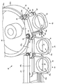
- a conveyor device 10 shown in the figure Tube filling machine has a belt-shaped endless belt 12 on, which is guided over pulleys 11, of which only one is shown.
- a plurality of support devices 13 are mounted, each a plate-like base part 15, which is parallel to the outside of the endless belt 12, and one of the base part 15 outwardly projecting support plate 14 comprises an insertion opening 14a for not shown Owns the tube holder.
- the support device 13 At the opposite end of the support device 13 are on the top and bottom of the base part 15, i.e. each near one of the longitudinal edges 12a and 12b of the endless belt 12 pins 18 mounted parallel to the bolt 16 run and a pivot bracket 20 each pivotable store the beyond with a bore 20a Bolts 16 of the adjacent support device and is also pivotable about this.
- the bolt 16 projects over the top Carrier 13 addition and can in this way a straight section of the conveyor, i.e. in a section between the pulleys into a engage correspondingly arranged guide rail 17, which has a U-profile that is open at the bottom.
- the guide tabs are in the rectilinear section of the endless belt 12, i.e. offside the deflection rollers 13, substantially transversely to the direction of movement aligned so that adjacent support devices 13 lie close together. If a carrying device enters the deflection area at a deflection roller 11, it will be relative to the adjacent support device pivoted the bolt 16.
- a Length compensation in the longitudinal direction of the endless belt 12 by pivoting the hinge plates 20 around the pins 18 and the associated hinge pin 16.
Landscapes
- Engineering & Computer Science (AREA)
- Mechanical Engineering (AREA)
- Microelectronics & Electronic Packaging (AREA)
- Structure Of Belt Conveyors (AREA)
- Supplying Of Containers To The Packaging Station (AREA)
- Auxiliary Devices For And Details Of Packaging Control (AREA)
Abstract
Description
Die Erfindung betrifft eine Fördervorrichtung in einer Verpackungsmaschine, insbesondere einer Tubenfüllmaschine, mit einem über zumindest zwei Umlenkrollen geführten Endlosband, auf dessen Außenseite eine Vielzahl von Tragvorrichtungen angeordnet sind, die an ihrem einen Ende jeweils über einen quer zur Längserstreckung des Endlosbandes verlaufenden Bolzen gelenkig am Endlosband gelagert sind und an ihrem entgegengesetzten Ende mit der benachbarten Tragvorrichtung sowohl gelenkig als auch in Längsrichtung des Endlosbandes verschieblich in Eingriff stehen.The invention relates to a conveyor device in a Packaging machine, especially a tube filling machine, with one guided over at least two deflection rollers Endless belt on the outside of which a variety of Carriers are arranged on their one End each over a transverse to the longitudinal extension of the Endless belt running articulated on the endless belt are stored and at their opposite end with the adjacent support device both articulated and in Longitudinally slidably engaged in the belt stand.
Zum Befüllen und Verschließen einer Tube in einer Tubenfüllmaschine ist es notwendig, die Tube mittels einer Fördervorrichtung durch mehrere Arbeitsstationen zu führen, wobei die Tube üblicherweise in einem Tubenhalter aufgenommen ist, der in seinen Abmessungen an die der Tube angepaßt ist und die Tube unter enger Passung sicher trägt. Als Fördervorrichtung findet häufig ein sogenannter Ovalförderer Verwendung, der ein über zumindest zwei Umlenkrollen oder -räder geführtes Endlosband aufweist, bei dem es sich um einen Riemen, beispielsweise einen Zahnriemen, oder auch um eine Kette handeln kann. Auf der Außenseite des Endlosbandes sind eine Vielzahl von Tragvorrichtungen mit den genannten Tubenträgern montiert, die mit dem Endlosband umlaufen, wobei der Antrieb durch einen auf eine der Umlenkrollen einwirkenden Antriebsmotor erreicht wird.For filling and closing a tube in a tube filling machine it is necessary to use a tube Conveyor through multiple workstations lead, the tube usually in a tube holder is included, the dimensions of which the Tube is adjusted and the tube is secure under a tight fit wearing. A so-called conveying device is often found Oval conveyors use one over at least two Has deflection rollers or wheels guided endless belt, which is a strap, for example one Timing belt, or can also be a chain. On the Outside of the endless belt are a variety of carriers mounted with the tube supports mentioned, which circulate with the endless belt, the drive through a drive motor acting on one of the deflection rollers is achieved.
Die Qualität der Füll- und Verschlußoperationen und die Funktionssicherheit bzw. die Störanfälligkeit der Tubenfüllmaschine hängen wesentlich von der Positioniergenauigkeit der Tuben in den einzelnen Arbeitsstationen ab. Somit ist es notwendig, die Tragvorrichtungen bzw. Tubenhalter sicher und mit hoher Genauigkeit auf der Außenseite des Endlosbandes zu befestigen. Dabei müssen die Tragvorrichtungen jedoch so gelagert sein, daß benachbarte Tragvorrichtungen im Umlenkbereich des Endlosbandes an den Umlenkrollen sowohl eine relative Schwenkung als auch eine geringe Verschiebung in Längsrichtung des Endlosbandes ausführen können, um das Auftreten von Zwangskräften und Zwängungsspannungen zu vermeiden.The quality of the fill and seal operations and the Functional reliability and the susceptibility to failure of the tube filling machine depend essentially on the positioning accuracy the tubes in the individual workstations. It is therefore necessary to use the carrying devices or tube holders safely and with high accuracy on the outside to attach the endless belt. The Carriers, however, be stored so that neighboring Carriers in the deflection area of the endless belt the pulleys both a relative pivot as well a slight shift in the longitudinal direction of the endless belt can execute the occurrence of constraining forces and to avoid constraint stresses.
Bei Tubenfüllmaschinen ist es bekannt, jede Tragvorrichtung am Endlosband anzubringen, indem ein Bolzen auf der Außenseite des Endlosbandes fixiert wird, der auf der Außenoberfläche des Endlosbandes senkrecht zu dessen Längserstreckung verläuft. Diesen Bolzen umgreift die Tragvorrichtung mit zwei etwa entsprechend der Breite des Endlosbandes beabstandeten Bohrungen, so daß ein Schwenklager mit zwei in Breitenrichtung des Endlosbandes beabstandeten Lagerpunkten gebildet ist. Am entgegengesetzten Ende der Tragvorrichtung ist eine einzelne gabelförmige Aufnahme ausgebildet, die den Bolzen der benachbarten Tragvorrichtung umgreift, wobei der Bolzen in der gabelförmigen Aufnahme verschieblich ist. Auf diese Weise ist ein Schubgelenk gebildet, das die Längenänderungen zwischen den Bolzen zweier benachbarter Tragvorrichtungen während der Umlenkung an den Umlenkrollen ausgleichen kann.In tube filling machines, it is known to have any carrying device to be attached to the endless belt by a bolt on the Outside of the endless belt is fixed on the Outer surface of the endless belt perpendicular to it Longitudinal extension runs. This pin grips the Carrier with two approximately according to the width of the Endless belt spaced holes, so that a pivot bearing with two spaced apart in the width direction of the endless belt Bearing points is formed. On the opposite The end of the carrier is a single forked one Recording trained the bolt of the neighboring Grips support device, the bolt in the fork-shaped Recording is movable. That way a thrust joint formed that changes in length between the bolt of two adjacent supports compensate for the deflection rollers during the deflection can.
Es hat sich gezeigt, daß das Schubgelenk, das in der Regel aus Kunststoff besteht, im Laufe der Zeit einem hohen Verschleiß unterliegt, da es mit dem Bolzen nur über eine relativ kleine Fläche in Anlage steht, wodurch örtlich relativ hohe Belastungsspitzen auftreten können. Der Verschleiß wird noch dadurch unterstützt, daß für die Fördervorrichtung üblicherweise kein Schmiermittel verwendet wird, da die offenen Tuben aus hygienischen Gründen nicht mit Schmiermittel in Kontakt kommen dürfen. Darüber hinaus wäre der Wartungs- und Arbeitsaufwand, der zum Schmieren sämtlicher Gelenke einer entsprechenden Fördervorrichtung notwendig wäre, übermäßig hoch.It has been shown that the thrust joint, which in the Usually made of plastic, over time one subject to high wear and tear as it only works with the bolt over a relatively small area, which means Relatively high peak loads can occur locally. The wear is further supported by the fact that Conveyor device usually does not use lubricant is because the open tubes for hygienic reasons must not come into contact with lubricant. In addition, the maintenance and labor would be the for lubricating all joints of a corresponding one Conveyor would be excessively high.
Die Lagerung der bekannten Tragvorrichtungen ist eine Dreipunktlagerung mit zwei voneinander in Querrichtung beabstandeten reinen Drehlagern an dem Bolzen und einem am entgegengesetzten Ende angeordneten Schubgelenk. Auf diese Weise ist zwar eine statisch bestimmte Lagerung gegeben, wodurch Zwängungen vermieden sind, es hat sich jedoch gezeigt, daß die räumliche Stabilität einer derartigen Lagerung in manchen Situationen nicht ausreichend ist, da die Dreipunktlagerung aufgrund ihrer asymmetrischen Anordnung der Lagerpunkte zum Verkippen um die Diagonalachse neigt, wobei der Hebelarm der Lager zur Aufnahme des Kippmomentes relativ gering ist. Auf diese Weise ist eine steife Lagerung der Tragvorrichtungen bzw. Tubenträger nicht oder nur sehr schwer zu erreichen.The storage of the known carriers is one Three-point bearing with two in the transverse direction spaced pure pivot bearings on the bolt and one thrust joint arranged at the opposite end. On this way is a statically determined storage given, whereby constraints are avoided, it has however, showed that the spatial stability of such Storage is insufficient in some situations is because the three-point bearing due to its asymmetrical Arrangement of the bearing points for tilting around the Diagonal axis inclines, the lever arm of the bearing Recording the tilting moment is relatively low. To this Way is a rigid storage of the support devices or Tube carrier not or only very difficult to reach.
Der Erfindung liegt die Aufgabe zugrunde, eine Fördervorrichtung der genannten Art zu schaffen, die eine präzise Positionierung der Tragvorrichtungen über eine lange Betriebedauer gewährleistet.The invention has for its object a conveyor of the kind mentioned to create a precise Positioning of the support devices over a long Guaranteed operating time.
Diese Aufgabe wird erfindungsgemäß bei einer Fördervorrichtung in einer Verpackungsmaschine dadurch gelöst, daß die Tragvorrichtung mit der benachbarten Tragvorrichtung über zumindest eine Gelenklasche verbunden ist, die um eine erste Achse schwenkbar an der Tragvorrichtung und um eine dazu parallele zweite Achse schwenkbar an der benachbarten Tragvorrichtung angeschlossen ist.This object is achieved in a conveyor device solved in a packaging machine in that the carrying device with the neighboring carrying device is connected via at least one articulated strap which around a first axis pivotable on the support device and around a second axis parallel to it pivotable on the adjacent one Carrier is connected.
Die Gelenklasche steht vorzugsweise schräg zur Längserstreckung des Förderbandes, so daß der gegenseitige Abstand zweier benachtarter Tragvorrichtungen durch Änderung der Schrägstellung der Gelenklasche ausgeglichen werden kann, ohne daß es zu Zwängungskräften führt. Darüber hinaus bleiben die benachbarten Tragvorrichtungen über die Gelenklasche relativ zueinander schwenkbar. Bei reinen Drehbewegungen liegen günstigere Reibungs- und Gleitverhältnisse als bei Schubbewegungen vor, so daß das Verschleißverhalten der Drehgelenke in den Gelenklaschen geringer als das bei dem bekannten Schubgelenk ist, wodurch die Standzeit der Fördervorrichtung wesentlich erhöht ist. Darüber hinaus ist die räumliche Stabilität insbesondere hinsichtlich des Kippverhaltens infolge der Gelenklaschen deutlich höher als bei dem Schubgelenk mit umgreifender gabelförmiger Aufnahme. Dadurch ist die Stabilität der Fördervorrichtung insgesamt erhöht, so daß sich vorbestimmte Positionen mit hoher Genauigkeit reproduzierbar einstellen lassen, was günstig für die Qualität der abgefüllten und verschlossenen Tuben ist.The hinge bracket is preferably at an angle to the longitudinal extent of the conveyor belt so that the mutual Distance between two night-time carriers Changes in the inclination of the joint plate compensated can become, without leading to constraining forces. In addition, the neighboring supports remain can be pivoted relative to one another via the joint plate. At pure rotary movements are more favorable friction and Sliding conditions than with thrust movements before, so that Wear behavior of the swivel joints in the joint plates is less than that of the known thrust joint, whereby the service life of the conveyor is essential is increased. In addition, the spatial stability especially with regard to the tipping behavior due to the Articulated brackets significantly higher than with the thrust joint encompassing fork-shaped receptacle. This is the Overall stability of the conveyor increased, so that predetermined positions are reproducible with high accuracy let set what is favorable for the quality the filled and sealed tubes.
In bevorzugter Ausgestaltung der Erfindung sind die benachbarten Tragvorrichtungen über jeweils zwei Gelenklaschen miteinander verbunden, so daß insgesamt für jede Tragvorrichtung eine Vierpunktlagerung erreicht ist, indem zwei beabstandete Lagerpunkte an dem Bolzen an dem einen Ende der Tragvorrichtung und zwei ebenfalls beabstandete Lagerpunkte an den beiden Gelenklaschen am anderen Ende der Tragvorrichtung vorgesehen sind. Dabei sollten die Gelenklaschen möglichst weit auseinanderliegen, was insbesondere dann erreicht ist, wenn sie jeweils nahe einer der Längskanten des Endlosbandes angeordnet sind. Durch die Vierpunktlagerung wird die Aufhängung der Tragvorrichtungen außergewöhnlich steif, so daß die Tuben mit hoher Präzision durch die Tubenfüllmaschine geführt werden können. Theoretisch ist eine Vierpunktlagerung zwar überbestimmt, in der Praxis hat sich jedoch gezeigt, daß keine Gefahr der Überlastung der Lagerung besteht, da bei heutzutage üblichen Fertigungstoleranzen die geometrische Abweichung der Lagerpunkte vom Sollwert sehr gering gehalten werden kann und andererseits durch die Elastizität des Gesamtsystems und insbesondere des Endlosbandes ausgeglichen werden kann, wodurch theoretisch mögliche Lastspitzen abgebaut werden.In a preferred embodiment of the invention adjacent support devices via two hinge plates interconnected so that overall for each A four-point bearing is reached, by two spaced bearing points on the bolt on the one end of the support device and two also spaced apart Bearing points on the two link plates on other end of the support device are provided. Here the hinges should be as far apart as possible, which is achieved in particular if each of them arranged near one of the longitudinal edges of the endless belt are. Due to the four-point bearing, the suspension of the Carriers exceptionally stiff, so that the tubes guided through the tube filling machine with high precision can be. Theoretically, a four-point bearing is overdetermined, but in practice it has been shown that there is no risk of overloading the storage, since with today's usual manufacturing tolerances the geometrical Deviation of the bearing points from the target value very much can be kept low and on the other hand by the Elasticity of the overall system and especially the endless belt can be compensated, which theoretically possible load peaks are reduced.
Äußere Kräfte, die beispielsweise beim Einsetzen und beim Ausheben des Tubenhalters einwirken, führen bei einer Vierpunktlagerung nicht mehr zu einem seitlichen Abkippen und werden durch die Tragvorrichtung weitestgehend abgefangen, da der Hebelarm zur Aufnahme von Kippmomenten aufgrund des gegenseitigen Abstandes der Lager wesentlich größer als bei einer Dreipunktlagerung ist.External forces, for example when inserting and when Take out the tube holder, lead to one Four-point support no longer tilts sideways and are largely intercepted by the carrying device, because the lever arm to absorb tilting moments due to the mutual distance between the bearings is larger than with a three-point bearing.
In bevorzugter Ausgestaltung ist vorgesehen, daß die Gelenklaschen bei geradlinig ausgerichten Tragvorrichtungen, d.h. im Bereich zwischen den Umlenkrollen, im wesentlichen senkrecht zur Längserstreckung des Endlosbandes ausgerichtet sind. Dadurch ist einerseits erreicht, daß benachbarte Tragvorrichtungen sehr dicht nebeneinander angeordnet sein können und die Gelenklaschen wenig Bauraum benötigen, wodurch die Anzahl der Tragvorrichtungen der Fördervorrichtung erhöht sein kann, andererseits ist sichergestellt, daß bei einer in Längsrichtung des Endlosbandes verlaufenden Relativbewegung benachbarter Tragvorrichtungen ausreichend Raum zum Ausgleich dieser Abstandsänderung durch Schrägstellung der Gelenklaschen vorhanden ist.In a preferred embodiment it is provided that the Articulated brackets in the case of straight-line supporting devices, i.e. in the area between the pulleys, essentially perpendicular to the longitudinal extension of the endless belt are aligned. On the one hand, that adjacent supports are very close together can be arranged and the hinge plates little Require installation space, reducing the number of support devices the conveyor can be increased, on the other hand it is ensured that at a in the longitudinal direction of the Endless belt running relative movement of neighboring Carriers enough space to compensate for this Distance change due to the inclination of the hinged straps is available.
In bevorzugter Ausgestaltung der Erfindung ist vorgesehen, daß die zweite Achse von dem am Endlosband angebrachten Bolzen der benachbarten Tragvorrichtung gebildet ist. Da die Gelenklaschen auf diese Weise den bereits vorhandenen Bolzen der benachbarten Tragvorrichtung mitbenutzen, kann die Lagerung sehr kompakt und mit relativ wenig Bauteilen realisiert werden.In a preferred embodiment of the invention, that the second axis of that attached to the endless belt Bolts of the adjacent support device are formed is. Because the hinge straps in this way already existing bolt of the adjacent support device share, the storage can be very compact and with relatively few components can be realized.
Vorzugsweise steht der Bolzen über die Tragvorrichtung hervor, so daß er in einem geradlinigen Abschnitt der Fördervorrichtung zwischen den Umlenkrollen in eine Führungsschiene eingreifen und dadurch die Tragvorrichtung sicher positionieren kann.The bolt preferably stands above the carrying device so that it is in a rectilinear section of the Conveyor between the pulleys in one Engage the guide rail and thereby the carrying device can position safely.
Weitere Einzelheiten und Merkmale der Erfindung sind aus der folgenden Beschreibung eines Ausführungsbeispiels unter Bezugnahme auf die Zeichnung ersichtlich, wobei die einzige Figur eine dreidimensionale Aufsicht auf eine Fördervorrichtung im Bereich einer Umlenkrolle zeigt.Further details and features of the invention are from the following description of an embodiment with reference to the drawing, the single figure a three-dimensional view of one Conveying device in the region of a deflecting roller shows.
Eine in der Figur dargestellte Fördervorrichtung 10 einer
Tubenfüllmaschine weist ein riemenförmiges Endlosband 12
auf, das über Umlenkrollen 11 geführt ist, von denen nur
eine dargestellt ist. Auf der Außenseite des Endlosbandes
12 sind eine Vielzahl von Tragvorrichtungen 13 montiert,
die jeweils ein plattenartiges Basisteil 15, das parallel
zur Außenseite des Endlosbandes 12 liegt, und eine von
dem Basisteil 15 nach außen vorstehende Tragplatte 14
umfaßt, die eine Einsetzöffnung 14a für nicht dargestellte
Tubenhalter besitzt. Am oberen und unteren Ende des
Basisteils 15, d.h. nahe den Längskanten 12a und 12b des
Endlosbandes 12 sind am Basisteil 15 im wesentlichen
senkrecht dazu verlaufende Seitenteile 15a, 15b angeformt,
so daß das Basisteil 15 zusammen mit den Seitenteilen
15a und 15b eine U-förmige Konfiguration bildet
und das Endlosband 12 teilweise umgreift.A
Auf der Außenseite des Endlosbandes 12 sind quer zu
seiner Längserstreckung ausgerichtete Bolzen 16 in bekannter
Weise befestigt, die jeweils eine Bohrung 19 in
den Seitenteilen 15a und 15b durchgreifen, so daß jede
Tragvorrichtung 13 um einen ihr zugeordneten Bolzen 16
schwenkbar ist, wobei das Schwenklager an einem Ende der
Tragvorrichtung ausgebildet ist.On the outside of the
Am entgegengesetzten Ende der Tragvorrichtung 13 sind auf
der Ober- und Unterseite des Basisteil 15, d.h. jeweils
nahe einer der Längskanten 12a und 12b des Endlosbandes
12 Stifte 18 montiert, die parallel zu dem Bolzen 16
verlaufen und jeweils eine Gelenklasche 20 schwenkbar
lagern, die darüber hinaus mit einer Bohrung 20a den
Bolzen 16 der benachbarten Tragvorrichtung umgreift und
auch um diesen schwenkbar ist. Auf diese Weise ist jede
Tragvorrichtung 13 mittels einer Vierpunktlagerung gehalten,
die sich aus den beiden Drehlagern zwischen den
Seitenteilen 15a und 15b und dem Bolzen 16 sowie den
beiden schwenkbar gelagerten Gelenklaschen 20 zusammensetzt.
Der Bolzen 16 ragt auf der Oberseite über die
Tragvorrichtung 13 hinaus und kann auf diese Weise in
einem geradlinigen Abschnitt der Fördervorrichtung, d.h.
in einem Abschnitt zwischen den Umlenkrollen in eine
entsprechend angeordnete Führungsschiene 17 eingreifen,
die ein nach unten offenes U-Profil besitzt.At the opposite end of the
Wie die Figur zeigt, sind die Führungslaschen in dem
geradlinigen Abschnitt des Endlosbandes 12, d.h. abseits
der Umlenkrollen 13, im wesentlichen quer zur Bewegungsrichtung
ausgerichtet, so daß benachbarte Tragvorrichtungen
13 dicht aneinanderliegen. Wenn eine Tragvorrichtung
in den Umlenkbereich an einer Umlenkrolle 11 eintritt,
wird sie relativ zu der benachbarten Tragvorrichtung um
den Bolzen 16 geschwenkt. Darüber hinaus erfolgt ein
Längenausgleich in Längsrichtung des Endlosbandes 12
durch eine Schwenkung der Gelenklaschen 20 um die Stifte
18 sowie den zugeordneten Gelenkbolzen 16.As the figure shows, the guide tabs are in the
rectilinear section of the
Claims (5)
Applications Claiming Priority (2)
| Application Number | Priority Date | Filing Date | Title |
|---|---|---|---|
| DE19919497 | 1999-04-29 | ||
| DE19919497A DE19919497A1 (en) | 1999-04-29 | 1999-04-29 | Conveyor in a packaging machine |
Publications (2)
| Publication Number | Publication Date |
|---|---|
| EP1048570A2 true EP1048570A2 (en) | 2000-11-02 |
| EP1048570A3 EP1048570A3 (en) | 2005-03-30 |
Family
ID=7906276
Family Applications (1)
| Application Number | Title | Priority Date | Filing Date |
|---|---|---|---|
| EP00107728A Withdrawn EP1048570A3 (en) | 1999-04-29 | 2000-04-11 | Conveyor device for a packaging machine |
Country Status (4)
| Country | Link |
|---|---|
| US (1) | US6405852B1 (en) |
| EP (1) | EP1048570A3 (en) |
| JP (1) | JP2000326926A (en) |
| DE (1) | DE19919497A1 (en) |
Cited By (2)
| Publication number | Priority date | Publication date | Assignee | Title |
|---|---|---|---|---|
| WO2013113464A1 (en) * | 2012-02-01 | 2013-08-08 | Khs Gmbh | Oval container treatment device |
| WO2016131546A1 (en) * | 2015-02-20 | 2016-08-25 | Interroll Holding Ag | Securing element for securing a carriage on an endless conveyor, carriage, conveyor apparatus and securing method |
Families Citing this family (12)
| Publication number | Priority date | Publication date | Assignee | Title |
|---|---|---|---|---|
| DE10211121A1 (en) * | 2002-03-14 | 2003-10-16 | Bosch Gmbh Robert | Transporting device for especially pharmaceutical containers has guide elements provided on conveyor belt and guided along upper conveyor belt run on legs of guide rail which is C-form in cross-section |
| DE102004012140A1 (en) * | 2004-03-12 | 2005-09-29 | Ina-Schaeffler Kg | Belt drive with an integrated generator, in particular starter generator |
| DE102006057711A1 (en) * | 2006-12-07 | 2008-06-12 | Volkswagen Ag | Conveyor unit for transporting piece goods, especially in vehicle manufacturing, has component holder which can be fastened on conveyor belt and is adapted to contour of piece goods |
| US7628424B2 (en) * | 2006-12-08 | 2009-12-08 | Innerworx, Llc | Trenching machine with linked chain |
| US20100088931A1 (en) * | 2008-10-09 | 2010-04-15 | Time Machine, Inc. | Trenching Chain |
| ITBO20120068A1 (en) * | 2012-02-15 | 2013-08-16 | Ima Ind Srl | MACHINE FOR FORMATION OF DISPOSABLE DRINKS FOR BEVERAGES |
| ITUD20120075A1 (en) * | 2012-04-26 | 2013-10-27 | Immobiliare Metalprogetti S R L | MOBILE SUPPORT GROUP FOR AN OBJECT TRANSFER CONVEYOR, AND OBJECT TRANSFER CONVEYOR INCLUDING THIS MOBILE SUPPORT GROUP |
| ES2617688T3 (en) * | 2013-03-06 | 2017-06-19 | Gima S.P.A. | Drink capsule machine for manufacturing single-use beverage capsules |
| ITBO20130439A1 (en) | 2013-08-05 | 2015-02-06 | Ima Ind Srl | MACHINE FOR PACKAGING DISPOSABLE DRINKS FOR BEVERAGES |
| JP6155212B2 (en) * | 2014-03-11 | 2017-06-28 | 日本碍子株式会社 | Carrier for conveying honeycomb molded body |
| EP3034441B1 (en) * | 2014-12-17 | 2017-04-19 | UHLMANN PAC-SYSTEME GmbH & Co. KG | Transport device for transporting products |
| IT202200010853A1 (en) * | 2022-05-25 | 2023-11-25 | Marchesini Group Spa | PRODUCT TRANSPORT SYSTEM USING A CLOSED LOOP TIMING BELT WITH VERTICAL DRIVE AXIS |
Citations (5)
| Publication number | Priority date | Publication date | Assignee | Title |
|---|---|---|---|---|
| DE1150021B (en) * | 1959-08-04 | 1963-06-06 | Sig Schweiz Industrieges | Conveyor device with the following entrainment organs at adjustable intervals |
| DE2407826A1 (en) * | 1974-02-19 | 1975-09-04 | Waldemar Glowatzki | Bucket conveyor with tiltingg buckets - has buckes joined to belts by swing arms perpendicular to belts as well as trunnions |
| FR2540842A1 (en) * | 1983-02-11 | 1984-08-17 | Fives Cail Babcock | DEVICE FOR FIXING BUCKETS ON THE BAND OF A CARRIER, IN PARTICULAR A BUCKET ELEVATOR |
| EP0875459A1 (en) * | 1997-04-30 | 1998-11-04 | IWK Verpackungstechnik GmbH | Tube-filling machine |
| EP1059248A1 (en) * | 1999-06-07 | 2000-12-13 | I. Tech Inc. | Belt-type carrier system |
Family Cites Families (15)
| Publication number | Priority date | Publication date | Assignee | Title |
|---|---|---|---|---|
| AT26955B (en) | 1905-09-16 | 1907-01-10 | Betty Auberle | Gloss paste. |
| US2758696A (en) * | 1954-09-30 | 1956-08-14 | Landis Machine Co | Work transfer mechanism |
| US3678774A (en) * | 1969-10-01 | 1972-07-25 | Manuf Des Machines Du Haut Rhi | Transmission device |
| US3854573A (en) * | 1973-07-30 | 1974-12-17 | Neenah Foundry Co | Load carrier with dual pin suspension |
| NL7409757A (en) * | 1974-07-18 | 1976-01-20 | Ihc Holland Nv | BUCKET DREDGING MILL. |
| US4232783A (en) * | 1979-03-19 | 1980-11-11 | Westinghouse Electric Corp. | Step link for transportation apparatus |
| DE3321018A1 (en) * | 1983-06-10 | 1984-12-13 | Otmar Fahrion | CHAIN CONVEYOR UNIT |
| DE3905780C1 (en) * | 1989-02-24 | 1990-01-25 | Gebr. Heller Maschinenfabrik Gmbh, 7440 Nuertingen, De | |
| JPH0543026A (en) * | 1989-09-22 | 1993-02-23 | Eretsutsu:Kk | Conveyor device |
| IT1241046B (en) * | 1990-03-14 | 1993-12-29 | Metalprogetti Di Santicchi Augusto & C. | SEGMENTED CONVEYOR AND TRANSPORTATION BELT TO BE USED ON SINGLE RAIL CONVEYOR PLANTS. |
| US5305872A (en) * | 1992-01-30 | 1994-04-26 | Esco Corporation | Chain |
| FR2691956B1 (en) * | 1992-06-05 | 1994-08-26 | Sidel Sa | Device for loading containers on a transport element. |
| US5351811A (en) * | 1992-10-29 | 1994-10-04 | Tisma Machinery Corp. | Serpentine conveyors especially for automatic packaging machine |
| US5857558A (en) * | 1996-05-31 | 1999-01-12 | Riverwood International Corporation | Connector for attaching items to a chain for a packaging machine |
| US5921368A (en) * | 1997-02-25 | 1999-07-13 | Knight Industries, Inc. | Linked carrier gravity conveyor |
-
1999
- 1999-04-29 DE DE19919497A patent/DE19919497A1/en not_active Withdrawn
-
2000
- 2000-04-11 EP EP00107728A patent/EP1048570A3/en not_active Withdrawn
- 2000-04-25 JP JP2000124062A patent/JP2000326926A/en not_active Withdrawn
- 2000-04-26 US US09/558,590 patent/US6405852B1/en not_active Expired - Fee Related
Patent Citations (5)
| Publication number | Priority date | Publication date | Assignee | Title |
|---|---|---|---|---|
| DE1150021B (en) * | 1959-08-04 | 1963-06-06 | Sig Schweiz Industrieges | Conveyor device with the following entrainment organs at adjustable intervals |
| DE2407826A1 (en) * | 1974-02-19 | 1975-09-04 | Waldemar Glowatzki | Bucket conveyor with tiltingg buckets - has buckes joined to belts by swing arms perpendicular to belts as well as trunnions |
| FR2540842A1 (en) * | 1983-02-11 | 1984-08-17 | Fives Cail Babcock | DEVICE FOR FIXING BUCKETS ON THE BAND OF A CARRIER, IN PARTICULAR A BUCKET ELEVATOR |
| EP0875459A1 (en) * | 1997-04-30 | 1998-11-04 | IWK Verpackungstechnik GmbH | Tube-filling machine |
| EP1059248A1 (en) * | 1999-06-07 | 2000-12-13 | I. Tech Inc. | Belt-type carrier system |
Cited By (4)
| Publication number | Priority date | Publication date | Assignee | Title |
|---|---|---|---|---|
| WO2013113464A1 (en) * | 2012-02-01 | 2013-08-08 | Khs Gmbh | Oval container treatment device |
| US9221613B2 (en) | 2012-02-01 | 2015-12-29 | Khs Gmbh | Oval container treatment device |
| WO2016131546A1 (en) * | 2015-02-20 | 2016-08-25 | Interroll Holding Ag | Securing element for securing a carriage on an endless conveyor, carriage, conveyor apparatus and securing method |
| US9957110B2 (en) | 2015-02-20 | 2018-05-01 | Interoll Holding Ag | Securing element for securing a carriage on an endless conveyor, carriage, conveyor apparatus and securing method |
Also Published As
| Publication number | Publication date |
|---|---|
| DE19919497A1 (en) | 2000-11-02 |
| JP2000326926A (en) | 2000-11-28 |
| US6405852B1 (en) | 2002-06-18 |
| EP1048570A3 (en) | 2005-03-30 |
Similar Documents
| Publication | Publication Date | Title |
|---|---|---|
| EP1466108B1 (en) | Energy guiding device with reduced friction forces | |
| EP1048570A2 (en) | Conveyor device for a packaging machine | |
| DE3500704C2 (en) | Distribution conveyor for general cargo | |
| DE3241924A1 (en) | DEVICE FOR GUIDING FLEXIBLE SUPPLY PIPES | |
| DE2537943A1 (en) | ENDLESS CHAIN CONVEYOR, IN PARTICULAR FOR MOTOR VEHICLES | |
| EP0080625B1 (en) | Deflecting station for cover-belt conveyors with currugated side walls for use in loading installations with vertical and horizontal branches | |
| EP0104366B1 (en) | Continuous conveyor, especially a carrying-chain conveyor | |
| DE3024803A1 (en) | TRANSPORT DEVICE, IN PARTICULAR. FOR PACKAGING MACHINES | |
| EP0391247A2 (en) | Conveyor belt having accumulating rollers | |
| EP1995204A1 (en) | Device for longitudinally adjusting a spreader | |
| DE69321990T2 (en) | Linear bearings with rollers that have a curved profile | |
| EP0802130B1 (en) | Transport system | |
| DE102006026743A1 (en) | transport chain | |
| DE3327202C2 (en) | Belt stacker | |
| DE4229971C2 (en) | Cam roller bracket | |
| EP1050471A2 (en) | Folding-box conveyor for packaging machine | |
| DE29802927U1 (en) | Support device | |
| DE4411965C1 (en) | Cooling box for hollow glass article mfg. machine | |
| EP0616067B1 (en) | Tenterdevice | |
| DE9400343U1 (en) | Floor conveyor system | |
| EP0173182A1 (en) | Lifting and pivoting device for the emptying section of a tubular rubble chute | |
| EP0431419B1 (en) | Mechanical seal and device for sealing a rotating pipe against a fixed casing | |
| DE29810942U1 (en) | Deflection device | |
| DE102005044538B4 (en) | Conveyor device | |
| EP1705770A1 (en) | Method for operating an energy guiding chain and stowage gutter for performing the method |
Legal Events
| Date | Code | Title | Description |
|---|---|---|---|
| PUAI | Public reference made under article 153(3) epc to a published international application that has entered the european phase |
Free format text: ORIGINAL CODE: 0009012 |
|
| AK | Designated contracting states |
Kind code of ref document: A2 Designated state(s): AT BE CH CY DE DK ES FI FR GB GR IE IT LI LU MC NL PT SE |
|
| AX | Request for extension of the european patent |
Free format text: AL;LT;LV;MK;RO;SI |
|
| PUAL | Search report despatched |
Free format text: ORIGINAL CODE: 0009013 |
|
| AK | Designated contracting states |
Kind code of ref document: A3 Designated state(s): AT BE CH CY DE DK ES FI FR GB GR IE IT LI LU MC NL PT SE |
|
| AX | Request for extension of the european patent |
Extension state: AL LT LV MK RO SI |
|
| RIC1 | Information provided on ipc code assigned before grant |
Ipc: 7B 65G 17/42 B Ipc: 7B 65B 43/52 A |
|
| AKX | Designation fees paid | ||
| REG | Reference to a national code |
Ref country code: DE Ref legal event code: 8566 |
|
| STAA | Information on the status of an ep patent application or granted ep patent |
Free format text: STATUS: THE APPLICATION IS DEEMED TO BE WITHDRAWN |
|
| 18D | Application deemed to be withdrawn |
Effective date: 20051001 |