EP0484623B1 - Forging press - Google Patents
Forging press Download PDFInfo
- Publication number
- EP0484623B1 EP0484623B1 EP91108508A EP91108508A EP0484623B1 EP 0484623 B1 EP0484623 B1 EP 0484623B1 EP 91108508 A EP91108508 A EP 91108508A EP 91108508 A EP91108508 A EP 91108508A EP 0484623 B1 EP0484623 B1 EP 0484623B1
- Authority
- EP
- European Patent Office
- Prior art keywords
- forging press
- displaceable
- press according
- sliding table
- spar
- Prior art date
- Legal status (The legal status is an assumption and is not a legal conclusion. Google has not performed a legal analysis and makes no representation as to the accuracy of the status listed.)
- Expired - Lifetime
Links
- 238000005242 forging Methods 0.000 title claims abstract description 23
- 210000002105 tongue Anatomy 0.000 claims 1
- 238000006073 displacement reaction Methods 0.000 description 14
- 238000005461 lubrication Methods 0.000 description 2
- 238000005096 rolling process Methods 0.000 description 2
- 229910000906 Bronze Inorganic materials 0.000 description 1
- 239000010974 bronze Substances 0.000 description 1
- KUNSUQLRTQLHQQ-UHFFFAOYSA-N copper tin Chemical compound [Cu].[Sn] KUNSUQLRTQLHQQ-UHFFFAOYSA-N 0.000 description 1
- 230000003247 decreasing effect Effects 0.000 description 1
- 230000008021 deposition Effects 0.000 description 1
- 239000004519 grease Substances 0.000 description 1
- 238000005259 measurement Methods 0.000 description 1
- 239000000203 mixture Substances 0.000 description 1
- 230000035515 penetration Effects 0.000 description 1
- 238000009991 scouring Methods 0.000 description 1
Images

Classifications
-
- B—PERFORMING OPERATIONS; TRANSPORTING
- B21—MECHANICAL METAL-WORKING WITHOUT ESSENTIALLY REMOVING MATERIAL; PUNCHING METAL
- B21J—FORGING; HAMMERING; PRESSING METAL; RIVETING; FORGE FURNACES
- B21J13/00—Details of machines for forging, pressing, or hammering
- B21J13/08—Accessories for handling work or tools
- B21J13/085—Accessories for handling work or tools handling of tools
-
- B—PERFORMING OPERATIONS; TRANSPORTING
- B30—PRESSES
- B30B—PRESSES IN GENERAL
- B30B15/00—Details of, or accessories for, presses; Auxiliary measures in connection with pressing
- B30B15/02—Dies; Inserts therefor; Mounting thereof; Moulds
- B30B15/028—Loading or unloading of dies, platens or press rams
Definitions
- the invention relates to a forging press with a sliding table carrying tools.
- a lifting and lowering tool carrier plate or a sliding table has become known from German design specification 21 61 917.
- the sliding table has running wheels on rails of the press table, which are rotatably mounted on eccentrically arranged axle journals of bolts, the bolts being rotatable by a motor-driven swivel device for pulling in and extending the wheels into and out of the tool carrier plate, so that the Can raise and lower the tool carrier plate opposite the press table.
- stops arranged on the tool carrier plate press against counter stops of the press frame and brace the tool carrier plate with the press.
- the invention has for its object to make the table displacement unit with simple means reliable in a forging press of the type mentioned and thereby reduce the structural complexity and the susceptibility to failure of the forging press.
- the sliding table is arranged on a table rail having a roller conveyor with lifting and lowering rollers and the sliding table and the table rail are provided on their mutually facing surfaces with interlocking detents which are offset from one another by a pitch.
- the two measures combined with one another according to the invention, namely the rollers which can be raised and lowered in the roller conveyor formed on the table beam, and the detents which enable the sliding table to be fixed in a new position in a simple manner bring numerous advantages for the operation of a forging press .
- the lifting and lowering of the rollers creates the prerequisite that the locking of the sliding table and the table spar - advantageously locking plates protrude from the sliding table and the roller conveyor and are offset from one another by a desired division dimension to be determined by the plate width - after lifting the The sliding table is exposed beyond the cantilever dimension, thus allowing the table with the tools attached to it to be moved relative to the roller conveyor locks into the new operating position.
- the sliding table then only needs to be lowered, so that the locks, preferably bevelled on their long sides or edges, snap into one another and fix the sliding table on the slideway (press table or table spar) without any further measures.
- interlocking or lockable detents allow a significantly higher axial table locking than is the case with cylinder holding forces or table locking bolts, etc., because the detents are suitable for absorbing high forces, such as those that exist in forging presses. Since axial table displacement forces thus occurring are conducted directly into the table or press spar, a much simpler and cheaper displacement cylinder arrangement can also be made possible for this reason; in addition, axial displacement forces do not have to be introduced into the foundation, which can therefore be carried out with less effort.
- interchangeable locking plates which are screwed to the sliding table, for example, the pitch and thus the displacement of the sliding table can be increased or decreased in a simple manner according to the respective requirements and tool measurements by using wider or narrower locking plates.
- rollers can preferably be permanently lubricated.
- the roller conveyor or the entire under-table area can thus be kept free of surface grease; So-called scouring paste - a mixture of scale and fat - as inevitable with the known slideways, cannot arise.
- the encapsulated or partitioned roller bearing reduces fat consumption to almost zero.
- No lubrication hoses need to be connected to the sliding table, so that an otherwise required cable drag chain can be omitted.
- the previously lubricated slideway e.g. made of bronze or cast plates, easily replaceable roller units are used.
- the space between the sliding table and table spar can be kept clear of scale by the compressed air routing in this way from the inside, even if a table top with the integrated roller conveyor during the pressing operation is curved upwards due to the heat Pressing pumps or the table is raised to move.
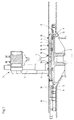
- a forging press 3 shown in FIG. 1 for reasons of better clarity with only one press stand 6, is adjustable in the direction of the double arrow (see FIGS. 3 and 4) Sliding table 4 arranged.
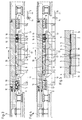
- the sliding table 4 lies flat on the table spar 2, as shown in the left half of Figure 2, and is secured by means of locking plates 5, 5 'against longitudinal displacement.
- the locking plates 5, 5 ' are along both longitudinal edges of the table spar 2 (see FIG. 2) and opposite, arranged in the sliding table 4 and locked into one another during forging, as shown in the right half of Figure 5.
- the locking plates 5, 5 ' are arranged on the mutually facing surfaces of the sliding table 4 and the table spar 2, namely the locking plates 5' in the sliding table 4 and the locking plates 5 in the table spar 2; they are offset from each other by a pitch T corresponding to the plate width.
- the detents could also consist, for example, of grooves in the table spar 2 and springs of the sliding table 4.
- the locking plates 5 and 5 ' are opposite the table spar 2 and the sliding table 4, and their long sides or edges are provided with inclined surfaces 19, with adjacent inclined surfaces of the upper and lower locking plates 5' and 5 when lowering the sliding table - or slide on each other and support the engagement of the upper locking plates 5 'in the gaps between the lower locking plates 5 of the table spar 2.
- the displacement table 4 carrying the tools is removed from its left half in FIG. 2 and in FIG. 3 shown position, in which it rests flat on the table spar 2, first raised hydraulically by means of roller units 8 until its locking plates 5 'are in one plane above the locking plates 5 of the table spar 2, as in the left half of Figure 5 and the right Half of Figure 2 shown.
- the roller units 8 are in cassette design executed (see FIGS. 3 and 4); in each cassette 9, two rollers 10 are encapsulated outwards and provided with permanent lubrication.
- transverse yoke 11 see the two roller units 8 shown in section in FIG. 3
- transverse yokes 11 are acted upon by actuating pistons 12, which are connected via lines 13 and an intermediate, multi-way valve 14 designed as a control valve to an unillustrated one Pressure medium source are connected.
- the lifted shifting table 4 is adjusted by means of a shifting cylinder 16 by a displacement distance corresponding to twice the pitch T, namely until the locking plates 5 'of the shifting table 4 are above one Gap between two locking plates 5 of the table spar 2 are reached, into which they snap when lowered, so that the upper and lower locking plates 5 'and 5 interlock.
- the table stroke or adjustment path (2 x pitch T) is determined by the width of the interchangeable locking plates 5, 5 'which can be variably adapted to the respective operating requirements.
- the rolling friction achieved when the displacement table 4 moves due to the raised rollers 10 of the roller units 8 makes it possible to dimension the displacement cylinder 16 much smaller than is the case with known forging presses with - also fast-wearing - tables to be displaced in guideways or slideways.
Landscapes
- Engineering & Computer Science (AREA)
- Mechanical Engineering (AREA)
- Forging (AREA)
- Saccharide Compounds (AREA)
Abstract
Description
Die Erfindung betrifft eine Schmiedepresse mit einem Werkzeuge tragenden Verschiebetisch.The invention relates to a forging press with a sliding table carrying tools.
Zwar nicht für eine Schmiedepresse, jedoch für eine Presse anderer Bauart ist durch die deutsche Auslegeschrift 21 61 917 eine heb- und senkbare Werkzeugträgerplatte bzw. ein Verschiebetisch bekannt-geworden. Der Verschiebetisch weist auf Schienen des Pressentisches laufende Räder auf, die auf exzentrisch angeordneten Achszapfen von Bolzen drehantreibbar gelagert sind, wobei sich die Bolzen durch eine motorisch betriebene Schwenkeinrichtung zum Einziehen und Ausfahren der Räder in bzw. aus der Werkzeugträgerplatte verdrehen lassen, so daß sich die Werkzeugträgerplatte gegenüber dem Pressentisch heben und senken läßt. Wahrend des Einziehens der Räder pressen sich an der Werkzeugträgerplatte angeordnete Anschläge an Gegenanschläge des Pressenrahmens an und verspannen die Werkzeugträgerplatte mit der Presse. Aufgrund dieser speziellen Gegenanschläge, die nämlich als axial nach außen ragende, abgesetzte Verlängerungen der Räder ausgebildet sind, bedarf es zum Festklemmen und Anheben der Werkzeugträgerplatte dort einiger drehbar in Büchsen der Werkzeugträgerplatte gelagerter Exzenterbolzen. Bei Schwenkung der Exzenterbolzen durch Hydraulikzylinder wird die Werkzeugträgerplatte zunächst auf den Pressentisch abgesenkt; werden nun in dieser Position die Exzenterbolzen weitergedreht, heben sich die Räder an und werden deren angesetzten Verlängerungen nach oben bewegt und gegen die darüber angeordneten Anschläge gedrückt. Hierdurch wird die Werkzeugträgerplatte an den Pressentisch festgeklemmt.Not for a forging press, but for a press of a different type, a lifting and lowering tool carrier plate or a sliding table has become known from German design specification 21 61 917. The sliding table has running wheels on rails of the press table, which are rotatably mounted on eccentrically arranged axle journals of bolts, the bolts being rotatable by a motor-driven swivel device for pulling in and extending the wheels into and out of the tool carrier plate, so that the Can raise and lower the tool carrier plate opposite the press table. During the retraction of the wheels, stops arranged on the tool carrier plate press against counter stops of the press frame and brace the tool carrier plate with the press. Due to these special counter-stops, which are designed as axially projecting, remote extensions of the wheels, some eccentric bolts, which are rotatably mounted in bushes of the tool carrier plate, are required there to clamp and lift the tool carrier plate. When the eccentric bolts are swiveled by hydraulic cylinders, the tool carrier plate is first lowered onto the press table; If the eccentric bolts are rotated further in this position, the wheels rise and their extensions are moved upwards and pressed against the stops arranged above them. As a result, the tool carrier plate is clamped to the press table.
Der Erfindung liegt die Aufgabe zugrunde, bei einer Schmiedepresse der eingangs genannten Art die Tischverschiebeeinheit mit einfachen Mitteln betriebssicher zu gestalten und dabei den baulichen Aufwand sowie die Störanfälligkeit der Schmiedepresse zu verringern.The invention has for its object to make the table displacement unit with simple means reliable in a forging press of the type mentioned and thereby reduce the structural complexity and the susceptibility to failure of the forging press.
Diese Aufgabe wird erfindungsgemäß dadurch gelöst, daß der Verschiebetisch auf einem eine Rollenbahn mit heb- und senkbaren Rollen aufweisenden Tischholm angeordnet ist und der Verschiebetisch und der Tischholm an ihren einander zugewandten Flächen mit ineinandergreifenden Arretierungen versehen sind, die um ein Teilungsmaß gegeneinander versetzt sind. Die beiden erfindungsgemäß miteinander kombinierten Maßnahmen, nämlich die heb- und senkbar in der auf dem Tischholm ausgebildeten Rollenbahn angeordneten Rollen sowie die auf einfache Art und Weise die Feststellung des Verschiebetisches in einer neuen Position ermoglichenden Arretierungen bringen gleich zahlreiche Vorteile für den Betrieb einer Schmiedepresse mit sich. Die Heb- und Senkbarkeit der Rollen schafft hierbei die Voraussetzung, daß die Arretierung des Verschiebetisches und des Tischholms - vorteilhaft kragen Arretierungsplatten aus dem Verschiebetisch und der Rollenbahn vor und sind um ein gewünschtes, durch die Plattenbreite zu bestimmendes Teilungsmaß gegeneinander versetzt - nach dem Anheben des Verschiebetisches über das Vorkragmaß hinaus freiliegen und somit ein Verschieben des Tisches mit den darauf befestigten Werkzeugen relativ zu den Arretierungen der Rollenbahn bis in die neue Betriebsposition ermöglichen.This object is achieved in that the sliding table is arranged on a table rail having a roller conveyor with lifting and lowering rollers and the sliding table and the table rail are provided on their mutually facing surfaces with interlocking detents which are offset from one another by a pitch. The two measures combined with one another according to the invention, namely the rollers which can be raised and lowered in the roller conveyor formed on the table beam, and the detents which enable the sliding table to be fixed in a new position in a simple manner bring numerous advantages for the operation of a forging press . The lifting and lowering of the rollers creates the prerequisite that the locking of the sliding table and the table spar - advantageously locking plates protrude from the sliding table and the roller conveyor and are offset from one another by a desired division dimension to be determined by the plate width - after lifting the The sliding table is exposed beyond the cantilever dimension, thus allowing the table with the tools attached to it to be moved relative to the roller conveyor locks into the new operating position.
Der Verschiebetisch braucht dann nur noch abgesenkt zu werden, so daß die vorzugsweise an ihren Längsseiten oder -kanten angeschrägten Arretierungen formschlüssig ineinanderrasten und den Verschiebetisch auf der Gleitbahn (Pressentisch bzw. Tischholm) ohne weitere Maßnahme festlegen.The sliding table then only needs to be lowered, so that the locks, preferably bevelled on their long sides or edges, snap into one another and fix the sliding table on the slideway (press table or table spar) without any further measures.
Abgesehen davon, daß der bisher eingesetzte hydraulische Verschiebezylinder wesentlich kleiner sein kann, denn es liegt lediglich noch Rollreibung vor, muß er außerdem nicht mehr eine hohe Haltekraft zum Festlegen des Verschiebetisches in der jeweiligen Betriebsposition aufbringen. Er kann somit wesentlich kleiner dimensioniert oder durch andere Antriebselemente ersetzt werden, so daß für besonders große Tischhübe z.B. auch Öl- Motoren eingesetzt werden könnten.Apart from the fact that the hydraulic displacement cylinder used up to now can be considerably smaller, since there is only rolling friction, it also no longer has to exert a high holding force for fixing the displacement table in the respective operating position. It can thus be dimensioned much smaller or replaced by other drive elements, so that, for example, oil motors could also be used for particularly large table strokes.
Schließlich lassen die ineinandergreifenden bzw. -rastbaren Arretierungen eine wesentlich höhere axiale Tischfeststellung zu, als das bei Zylinderhaltekräften oder Tischverriegelungsbolzen etc. der Fall ist, denn die Arretierungen sind zur Aufnahme hoher Verkräfte geeignet, wie sie insbesondere bei Schmiedepressen vorliegen. Da somit auftretende axiale Tischverschiebe- kräfte direkt in den Tisch- bzw. Pressenholm geleitet werden, läßt sich auch aus diesem Grunde eine wesentlich einfachere und billigere Verschiebezylinderanordnung ermöglichen; außerdem brauchen axiale Verschiebekräfte nicht in das Fundament eingeleitet zu werden, das somit weniger aufwendig ausgeführt werden kann.Finally, the interlocking or lockable detents allow a significantly higher axial table locking than is the case with cylinder holding forces or table locking bolts, etc., because the detents are suitable for absorbing high forces, such as those that exist in forging presses. Since axial table displacement forces thus occurring are conducted directly into the table or press spar, a much simpler and cheaper displacement cylinder arrangement can also be made possible for this reason; in addition, axial displacement forces do not have to be introduced into the foundation, which can therefore be carried out with less effort.
Wenn statt gefräster Arretierungen allerdings vorteilhaft austauschbare Arretierungsplatten verwendet werden, die beispielsweise mit dem Verschiebetisch verschraubt sind, läßt sich das Teilungsmaß und damit der Verschiebeweg des Verschiebetisches durch Einsatz von breiteren oder schmaleren Arretierungsplatten auf einfache Weise entsprechend den jeweiligen Erfordernissen und Werkzeugmessungen vergrößern bzw. verringern.If, instead of milled detents, interchangeable locking plates are used, which are screwed to the sliding table, for example, the pitch and thus the displacement of the sliding table can be increased or decreased in a simple manner according to the respective requirements and tool measurements by using wider or narrower locking plates.
Es empfiehlt sich, zumindest jeweils zwei Rollen zu einer abgekapselten Rolleneinheit zusammenzufassen, wobei die Rollen vorzugsweise dauergeschmiert sein können. Die Rollenbahn bzw. der gesamte Untertischbereich läßt sich somit frei von Oberflächen-Schmierfett halten; sogenannte Scheuerpaste - ein Gemisch von Zunder und Fett -, wie bei den bekannten Gleitbahnen unvermeidlich, kann nicht entstehen. Die abgekapselte bzw. abgeschottete Rollenlagerung reduziert den Fettverbrauch auf nahezu Null. Es brauchen keine Schmierschläuche an den Verschiebetisch angeschlossen zu werden, so daß eine ansonsten erforderliche Kabelschleppkette entfallen kann. Statt der bisher notwendigen automatisch geschmierten Gleitbahn, z.B. aus Bronze- oder Gußplatten, werden somit leicht austauschbare Rolleneinheiten verwendet.It is advisable to combine at least two rollers to form an encapsulated roller unit, wherein the rollers can preferably be permanently lubricated. The roller conveyor or the entire under-table area can thus be kept free of surface grease; So-called scouring paste - a mixture of scale and fat - as inevitable with the known slideways, cannot arise. The encapsulated or partitioned roller bearing reduces fat consumption to almost zero. No lubrication hoses need to be connected to the sliding table, so that an otherwise required cable drag chain can be omitted. Instead of the previously lubricated slideway, e.g. made of bronze or cast plates, easily replaceable roller units are used.
Bei unter den Verschiebetisch verlegten Druckluftleitungen läßt sich durch die auf diese Weise von innen nach außen gerichtete Druckluftfühung der Zwischenraum von Verschiebetisch und Tischholm einfach von Zunder freihalten, und zwar auch dann, wenn eine während des Pressbetriebes hitzebedingt nach oben gewölbte Tischplatte mit der integrierten Rollenbahn beim Pressen pumpt oder der Tisch zum Verschieben angehoben wird.With compressed air lines installed under the sliding table, the space between the sliding table and table spar can be kept clear of scale by the compressed air routing in this way from the inside, even if a table top with the integrated roller conveyor during the pressing operation is curved upwards due to the heat Pressing pumps or the table is raised to move.
Die Erfindung wird nachfolgend anhand eines in der Zeichnung dargestellten Ausführungsbeispiels des näheren erläutert. In der Zeichnung zeigen:
Figur 1 im Teilquerschnitt eine Schmiedepresse mit erfindungsgemäßen Arretierungen von Verschiebetisch und Tischholm;Figur 2 im Querschnitt als Einzelheit den auf einem mit einer Rollenbahn versehenen Tischholm der Schmiedepresse nachFigur 1 angeordneten Verschiebetisch, in der linken Zeichnungshälfte abgesenkt und in der rechten Zeichnungshälfte angehoben dargestellt;- Figur 3 den abgesenkten Verschiebetisch entlang der Linie III-III von
Figur 2 geschnitten; Figur 4 den Verschiebetisch gemäß Figur 3 in der angehobenen Position dargestellt; undFigur 5 als Einzelheit eine Anordnung von Arretierungsplatten entlang der Linie V-V vonFigur 2 geschnitten.
- Figure 1 in partial cross section a forging press with locks according to the invention of the sliding table and table spar;
- 2 shows in cross section as a detail the sliding table arranged on a table rail of the forging press according to FIG. 1 provided with a roller conveyor, lowered in the left half of the drawing and raised in the right half of the drawing;
- Figure 3 shows the lowered sliding table along the line III-III of Figure 2;
- Figure 4 shows the sliding table of Figure 3 in the raised position; and
- Figure 5 cut as a detail an arrangement of locking plates along the line VV of Figure 2.
Auf einem mit einer Rollenbahn 1 ausgebildeten Tischholm 2 einer in Figur 1 aus Gründen der besseren Übersichtlichkeit mit lediglich einem Pressenständer 6 dargetstellten Schmiedepresse 3 ist ein in Richtung des Doppelpfeils (vergl. die Figuren 3 und 4) verstellbarer Verschiebetisch 4 angeordnet. Wahrend des Schmiedebetriebes liegt der Verschiebetisch 4 flächig auf dem Tischholm 2 auf, wie in der linken Hälfte von Figur 2 dargestellt, und wird mittels Arretierungsplatten 5, 5′ gegen Längsverschiebung gesichert. Die Arretierungsplatten 5, 5′ sind entlang beider Längsränder des Tischholms 2 (vergl. Figur 2) und gegenüberliegend, im Verschiebetisch 4 angeordnet und beim Schmiedebetrieb ineinandergerastet, wie in der rechten Hälfte von Figur 5 dargestellt. Die Arretierungsplatten 5, 5′ sind an den einander zugewandten Flächen des Verschiebetisches 4 und des Tischholms 2 angeordnet, und zwar sind die Arretierungsplatten 5′ im Verschiebetisch 4 und die Arretierungsplatten 5 im Tischholm 2 festgelegt; sie sind um ein der Plattenbreite entsprechendes Teilungsmaß T gegeneinander versetzt. Statt Platten könnten die Arretierungen beispielsweise auch aus Nuten im Tischholm 2 und Federn des Verschiebetisches 4 bestehen.On a
Die Arretierungsplatten 5 bzw. 5′ stehen gegenüber dem Tischholm 2 bzw. dem Verschiebetisch 4 vor, und ihre Längsseiten bzw. - kanten sind mit Schrägflächen 19 versehen, wobei benachbarte Schrägflächen der oberen und unteren Arretierungsplatten 5′ bzw. 5 beim Absenken des Verschiebetisches über- bzw. aufeinandergleiten und das Einrasten der oberen Arretierungsplatten 5′ in die Lücken zwischen den unteren Arretierungsplatten 5 des Tischholms 2 unterstützen.The
Um in Figur 1 mit Klemmleisten 20 auf dem Verschiebetisch 4 befestigte Werkzeuge 7 - von denen lediglich eins dargestellt ist - in eine neue Betriebsposition zu bringen, wird der die Werkzeuge tragende Verschiebetisch 4 aus seiner in der linken Hälfte von Figur 2 sowie der in Figur 3 dargestellten Lage, in der er flächig auf dem Tischholm 2 aufliegt, zunächst mittels Rolleneinheiten 8 hydraulisch soweit angehoben, bis sich seine Arretierungsplatten 5′ in einer Ebene über den Arretierungsplatten 5 des Tischholms 2 befinden, wie in der linken Hälfte von Figur 5 und der rechten Hälfte von Figur 2 dargestellt. Die Rolleneinheiten 8 sind in Kassettenbauweise ausgeführt (vergl. die Figuren 3 und 4); in jeder Kassette 9 sind zwei Rollen 10 nach außen abgekapselt und mit einer Dauerschmierung versehen gelagert. Sie sind über ein Querjoch 11 (vergl. die beiden in Figur 3 im Schnitt dargestellten Rolleneinheiten 8) miteinander verbunden, und die Querjoche 11 werden von Stellkolben 12 beaufschlagt, die über Leitungen 13 und ein zwischengeschaltetes, als Steuerventil ausgebildetes Mehrwegeventil 14 an eine nicht dargestellte Druckmittelquelle angeschlossen sind.In order to bring tools 7 - of which only one is shown - attached to the displacement table 4 in FIG. 1 with
In der abgesenkten Position des Verschiebetisches 4 und somit ineinander- gerasteten Arretierungsplatten 5, 5′ (vergl. die rechte Hälfte von Figur 5) werden beim Preßbetrieb unvermeidlich auftretende Querkräfte direkt in den Tischholm 2 geleitet. Die Kassetten 9 der Rolleneinheiten 8 liegen voll auf dem Tischholm 2 auf. Bei Beaufschlagung der Stellkolben 12 werden die Kassetten 9 der Rolleneinheiten 8 - wie in Figur 4 dargestellt - angehoben und damit auch der Verschiebetisch 4 entsprechend dem Hub 15 (vergl. Figur 4) der Stellkolben 12 von dem Tischholm 2 abgehoben. Der Hub 15 ist etwas größer als das Maß der gegenüber dem Tischholm 2 vorkragenden Arretierungsplatten 5. Der angehobene Verschiebetisch 4 wird mittels eines Verschiebezylinders 16 um einen dem doppelten Teilungsmaß T entsprechenden Verschiebweg verstellt, nämlich soweit, bis die Arretierungsplatten 5′ des Verschiebetisches 4 über einer Lücke zwischen zwei Arretierungsplatten 5 des Tischholmes 2 angelangt sind, in die sie beim Absenken einrasten, so daß sich die oberen und unteren Arretierungsplatten 5′ bzw. 5 regelrecht verzahnen. Der Tischhub bzw. Verstellweg (2 x Teilungsmaß T) wird durch die Breite der auswechselbaren und damit an die jeweiligen Betriebserfordernisse variabel anzupassenden Arretierungsplatten 5, 5′ bestimmt. Die bei Bewegungen des Verschiebetisches 4 aufgrund der angehobenen Rollen 10 der Rolleneinheiten 8 erreichte Rollreibung ermöglicht es, den Verschiebezylinder 16 weit kleiner zu dimensionieren, als das bei bekannten Schmiedepressen mit - außerdem schnell verschleißenden - in Führungs- oder Gleitbahnen zu verschiebenden Tischen der Fall ist.In the lowered position of the sliding table 4 and thus interlocking
Durch den Tischholm 2 geführte, unter den Verschiebetisch 4 verlegte Druckluftleitungen 17 enden mit ihren Mündungen 18 in dem Zwischenraum von Verschiebetisch 4 und Tischholm 2; kontinuierlich über die Druckluftleitungen 17 von einer nicht dargestellten Druckluftquelle einströmende Betriebsluft verhindert das Eindringen von Zunder und dessen Ablagerung auf der Rollenbahn 1 und dem Tischholm 2, wodurch die Standzeit der Rolleneinheiten 8 bzw. Rollen 10 erhöht sowie eine ungestörte Auflage des Verschiebetischs 4 auf dem Tischholm 2 erreicht und somit die Betriebssicherheit der Schmiedepresse 3 verbessert wird. Da zudem zum Festlegen des Verschiebetisches 4 keine mechanischen Klemmvorrichtungen bzw. Verriegelungen erforderlich sind, sondern die starr befestigten Arretierungsplatten 5, 5′ den Verschiebetisch 4 nach dem Absenken auf dem Tischholm 2 festlegen, ergibt sich mit einfachen Mitteln eine sichere, nicht störungsanfällige, ohne bewegliche Klemmelemente auskommende Tischfeststellung.
Claims (8)
characterized in that
the displaceable table (4) is arranged on a table post (2) having a roller track (1) with raisable and lowerable rollers (10) and the displaceable table (4) and the table post (2) are provided on their mutually facing surfaces with locking means (5, 5′) engaging in one another, these locking means (5, 5′) being offset with respect to one another by the pitch of one division (T).
characterized in that
the locking means are plates (5, 5′) projecting out of the displaceable table (4) and the table post (2).
characterized in that
the locking plates (5, 5′) are exchangeable.
characterized in that
the longitudinal sides of the locking means (5, 5′) are provided with oblique surfaces (19).
characterized in that
tongues and grooves of the displaceable table (4) and of the table post (2) form the locking means (5, 5′).
characterized in that
at least two rollers (10) in each case are grouped together to form an encapsulated roller unit (8).
characterized by
permanently lubricated rollers (10).
characterized by
compressed-air lines (17) laid below the displaceable table (4).
Priority Applications (4)
| Application Number | Priority Date | Filing Date | Title |
|---|---|---|---|
| ES199191108508T ES2033168T3 (en) | 1991-05-25 | 1991-05-25 | FORGING PRESS. |
| EP91108508A EP0484623B1 (en) | 1991-05-25 | 1991-05-25 | Forging press |
| DE9191108508T DE59100001D1 (en) | 1991-05-25 | 1991-05-25 | FORGING PRESS. |
| AT91108508T ATE76339T1 (en) | 1991-05-25 | 1991-05-25 | FORGING PRESS. |
Applications Claiming Priority (1)
| Application Number | Priority Date | Filing Date | Title |
|---|---|---|---|
| EP91108508A EP0484623B1 (en) | 1991-05-25 | 1991-05-25 | Forging press |
Publications (2)
| Publication Number | Publication Date |
|---|---|
| EP0484623A1 EP0484623A1 (en) | 1992-05-13 |
| EP0484623B1 true EP0484623B1 (en) | 1992-05-20 |
Family
ID=8206771
Family Applications (1)
| Application Number | Title | Priority Date | Filing Date |
|---|---|---|---|
| EP91108508A Expired - Lifetime EP0484623B1 (en) | 1991-05-25 | 1991-05-25 | Forging press |
Country Status (4)
| Country | Link |
|---|---|
| EP (1) | EP0484623B1 (en) |
| AT (1) | ATE76339T1 (en) |
| DE (1) | DE59100001D1 (en) |
| ES (1) | ES2033168T3 (en) |
Families Citing this family (4)
| Publication number | Priority date | Publication date | Assignee | Title |
|---|---|---|---|---|
| DE4127237A1 (en) * | 1991-08-17 | 1993-02-18 | Schuler Gmbh L | PRESS WITH PRESS AND SLIDING TABLE |
| SE518669C2 (en) * | 2001-03-13 | 2002-11-05 | Morphic Technologies Ab | Machine for making objects |
| EP3575012B1 (en) * | 2018-02-14 | 2021-12-29 | NSK Ltd. | Conveyance system, rocking-die forging method, rocking-die forging apparatus, bearing manufacturing method, vehicle manufacturing method, and machinery manufacturing method |
| CN111819015B (en) * | 2018-02-14 | 2022-06-07 | 日本精工株式会社 | Transport system, swing forging method, swing forging device, bearing manufacturing method, vehicle manufacturing method, and machine manufacturing method |
Family Cites Families (3)
| Publication number | Priority date | Publication date | Assignee | Title |
|---|---|---|---|---|
| DE2161917C3 (en) * | 1971-12-14 | 1979-04-26 | Maschinenfabrik Weingarten Ag, 7987 Weingarten | Movable, as well as raising and lowering tool carrier plate or sliding table for presses |
| DE2715782A1 (en) * | 1977-04-07 | 1978-10-19 | Ural Z Tjaschelogo Mash Im Ser | Tool magazine for forming press - has transfer cross slide linked to mounting platform on hydraulic press |
| CH667833A5 (en) * | 1985-04-09 | 1988-11-15 | Astrol S A | Machine tool pallet-changing mechanism - has pallet mounting bosses with self-centring action and securing clamps |
-
1991
- 1991-05-25 ES ES199191108508T patent/ES2033168T3/en not_active Expired - Lifetime
- 1991-05-25 DE DE9191108508T patent/DE59100001D1/en not_active Expired - Lifetime
- 1991-05-25 AT AT91108508T patent/ATE76339T1/en not_active IP Right Cessation
- 1991-05-25 EP EP91108508A patent/EP0484623B1/en not_active Expired - Lifetime
Also Published As
| Publication number | Publication date |
|---|---|
| EP0484623A1 (en) | 1992-05-13 |
| ES2033168T3 (en) | 1993-03-01 |
| ATE76339T1 (en) | 1992-06-15 |
| DE59100001D1 (en) | 1992-07-23 |
Similar Documents
| Publication | Publication Date | Title |
|---|---|---|
| DE2937972A1 (en) | DEVICE FOR APPLYING A SURFACE PRESSING TO PROGRESSIVE WORKPIECES | |
| EP0231445A1 (en) | Method and apparatus for the horizontal adjustment of rolls in a rolling mill | |
| EP1075943B1 (en) | Printing device | |
| EP0484623B1 (en) | Forging press | |
| DE3318314A1 (en) | DEVICE FOR SEPARATING THE INDIVIDUAL CUTS OF A STACK OF PUNCHED SHEETS | |
| DE2453857C2 (en) | Work roll changing device for a four-high roll stand for rolling sheet metal | |
| DE9110487U1 (en) | Device for overlapping welding of film edges | |
| EP0483599B1 (en) | Rolling stand comprising means for supporting the upper working roll in a spaced manner | |
| DE4117185A1 (en) | Forging press with movable sliding table - has table carrier with roller conveyor with raisable rollers, and locking devices on table and carrier | |
| DE4341431C2 (en) | Device for clamping and tensioning flexible pressure plates | |
| DE2224875C3 (en) | Device for loading and separating the rollers of a set of rollers used for processing webs, in particular paper webs | |
| DE2223150A1 (en) | ENTRANCE GUIDE TO BELT ROLLING MILLS | |
| DE3324562C2 (en) | Six-roll stand | |
| DE2723432C3 (en) | Table stop for a punching machine | |
| DE8713454U1 (en) | Device for rolling threads or similar profiles | |
| DE4122215C2 (en) | Automatic pallet changing device | |
| DE3523944C2 (en) | ||
| DE19937804A1 (en) | Printing unit for rotary printing machine has guides for setting adjustment paths of outer printing cylinders arranged at different directions from adjustment paths of inner printing cylinders | |
| EP0114174A1 (en) | Press for the manufacture of frames | |
| DE3811875A1 (en) | Guide arrangement | |
| DE2744529C3 (en) | Welding machine for electrical resistance butt welding | |
| DE4442567A1 (en) | Simplified driver unit for rolled strip | |
| DE2003263A1 (en) | Guiding cast strands to a cutting station | |
| DE3918242A1 (en) | Spacers esp. for working rollers in quatro-rolling stand - are freely movable in guide grooves in roller installation parts to facilitate roller replacement without damage to new rollers | |
| EP2195164A1 (en) | Printing unit having at least two lateral frame parts the distance of which can be changed relative to each other in a horizontal direction |
Legal Events
| Date | Code | Title | Description |
|---|---|---|---|
| ITF | It: translation for a ep patent filed | ||
| PUAI | Public reference made under article 153(3) epc to a published international application that has entered the european phase |
Free format text: ORIGINAL CODE: 0009012 |
|
| GRAA | (expected) grant |
Free format text: ORIGINAL CODE: 0009210 |
|
| 17P | Request for examination filed |
Effective date: 19910525 |
|
| AK | Designated contracting states |
Kind code of ref document: A1 Designated state(s): AT DE ES FR GB IT |
|
| AK | Designated contracting states |
Kind code of ref document: B1 Designated state(s): AT DE ES FR GB IT |
|
| REF | Corresponds to: |
Ref document number: 76339 Country of ref document: AT Date of ref document: 19920615 Kind code of ref document: T |
|
| REF | Corresponds to: |
Ref document number: 59100001 Country of ref document: DE Date of ref document: 19920723 |
|
| GBT | Gb: translation of ep patent filed (gb section 77(6)(a)/1977) | ||
| ET | Fr: translation filed | ||
| REG | Reference to a national code |
Ref country code: ES Ref legal event code: FG2A Ref document number: 2033168 Country of ref document: ES Kind code of ref document: T3 |
|
| PLBE | No opposition filed within time limit |
Free format text: ORIGINAL CODE: 0009261 |
|
| STAA | Information on the status of an ep patent application or granted ep patent |
Free format text: STATUS: NO OPPOSITION FILED WITHIN TIME LIMIT |
|
| 26N | No opposition filed | ||
| PGFP | Annual fee paid to national office [announced via postgrant information from national office to epo] |
Ref country code: FR Payment date: 19950426 Year of fee payment: 5 |
|
| PGFP | Annual fee paid to national office [announced via postgrant information from national office to epo] |
Ref country code: ES Payment date: 19950508 Year of fee payment: 5 |
|
| PGFP | Annual fee paid to national office [announced via postgrant information from national office to epo] |
Ref country code: DE Payment date: 19950512 Year of fee payment: 5 |
|
| PGFP | Annual fee paid to national office [announced via postgrant information from national office to epo] |
Ref country code: GB Payment date: 19950515 Year of fee payment: 5 |
|
| PGFP | Annual fee paid to national office [announced via postgrant information from national office to epo] |
Ref country code: AT Payment date: 19950522 Year of fee payment: 5 |
|
| PG25 | Lapsed in a contracting state [announced via postgrant information from national office to epo] |
Ref country code: GB Effective date: 19960525 Ref country code: AT Effective date: 19960525 |
|
| PG25 | Lapsed in a contracting state [announced via postgrant information from national office to epo] |
Ref country code: ES Free format text: LAPSE BECAUSE OF NON-PAYMENT OF DUE FEES Effective date: 19960527 |
|
| GBPC | Gb: european patent ceased through non-payment of renewal fee |
Effective date: 19960525 |
|
| PG25 | Lapsed in a contracting state [announced via postgrant information from national office to epo] |
Ref country code: FR Effective date: 19970131 |
|
| PG25 | Lapsed in a contracting state [announced via postgrant information from national office to epo] |
Ref country code: DE Effective date: 19970201 |
|
| REG | Reference to a national code |
Ref country code: FR Ref legal event code: ST |
|
| REG | Reference to a national code |
Ref country code: ES Ref legal event code: FD2A Effective date: 19990503 |
|
| PG25 | Lapsed in a contracting state [announced via postgrant information from national office to epo] |
Ref country code: IT Free format text: LAPSE BECAUSE OF NON-PAYMENT OF DUE FEES;WARNING: LAPSES OF ITALIAN PATENTS WITH EFFECTIVE DATE BEFORE 2007 MAY HAVE OCCURRED AT ANY TIME BEFORE 2007. THE CORRECT EFFECTIVE DATE MAY BE DIFFERENT FROM THE ONE RECORDED. Effective date: 20050525 |