EP0484623B1 - Presse à forger - Google Patents
Presse à forger Download PDFInfo
- Publication number
- EP0484623B1 EP0484623B1 EP91108508A EP91108508A EP0484623B1 EP 0484623 B1 EP0484623 B1 EP 0484623B1 EP 91108508 A EP91108508 A EP 91108508A EP 91108508 A EP91108508 A EP 91108508A EP 0484623 B1 EP0484623 B1 EP 0484623B1
- Authority
- EP
- European Patent Office
- Prior art keywords
- forging press
- displaceable
- press according
- sliding table
- spar
- Prior art date
- Legal status (The legal status is an assumption and is not a legal conclusion. Google has not performed a legal analysis and makes no representation as to the accuracy of the status listed.)
- Expired - Lifetime
Links
- 238000005242 forging Methods 0.000 title claims abstract description 23
- 210000002105 tongue Anatomy 0.000 claims 1
- 238000006073 displacement reaction Methods 0.000 description 14
- 238000005461 lubrication Methods 0.000 description 2
- 238000005096 rolling process Methods 0.000 description 2
- 229910000906 Bronze Inorganic materials 0.000 description 1
- 239000010974 bronze Substances 0.000 description 1
- KUNSUQLRTQLHQQ-UHFFFAOYSA-N copper tin Chemical compound [Cu].[Sn] KUNSUQLRTQLHQQ-UHFFFAOYSA-N 0.000 description 1
- 230000003247 decreasing effect Effects 0.000 description 1
- 230000008021 deposition Effects 0.000 description 1
- 239000004519 grease Substances 0.000 description 1
- 238000005259 measurement Methods 0.000 description 1
- 239000000203 mixture Substances 0.000 description 1
- 230000035515 penetration Effects 0.000 description 1
- 238000009991 scouring Methods 0.000 description 1
Images

Classifications
-
- B—PERFORMING OPERATIONS; TRANSPORTING
- B21—MECHANICAL METAL-WORKING WITHOUT ESSENTIALLY REMOVING MATERIAL; PUNCHING METAL
- B21J—FORGING; HAMMERING; PRESSING METAL; RIVETING; FORGE FURNACES
- B21J13/00—Details of machines for forging, pressing, or hammering
- B21J13/08—Accessories for handling work or tools
- B21J13/085—Accessories for handling work or tools handling of tools
-
- B—PERFORMING OPERATIONS; TRANSPORTING
- B30—PRESSES
- B30B—PRESSES IN GENERAL
- B30B15/00—Details of, or accessories for, presses; Auxiliary measures in connection with pressing
- B30B15/02—Dies; Inserts therefor; Mounting thereof; Moulds
- B30B15/028—Loading or unloading of dies, platens or press rams
Definitions
- the invention relates to a forging press with a sliding table carrying tools.
- a lifting and lowering tool carrier plate or a sliding table has become known from German design specification 21 61 917.
- the sliding table has running wheels on rails of the press table, which are rotatably mounted on eccentrically arranged axle journals of bolts, the bolts being rotatable by a motor-driven swivel device for pulling in and extending the wheels into and out of the tool carrier plate, so that the Can raise and lower the tool carrier plate opposite the press table.
- stops arranged on the tool carrier plate press against counter stops of the press frame and brace the tool carrier plate with the press.
- the invention has for its object to make the table displacement unit with simple means reliable in a forging press of the type mentioned and thereby reduce the structural complexity and the susceptibility to failure of the forging press.
- the sliding table is arranged on a table rail having a roller conveyor with lifting and lowering rollers and the sliding table and the table rail are provided on their mutually facing surfaces with interlocking detents which are offset from one another by a pitch.
- the two measures combined with one another according to the invention, namely the rollers which can be raised and lowered in the roller conveyor formed on the table beam, and the detents which enable the sliding table to be fixed in a new position in a simple manner bring numerous advantages for the operation of a forging press .
- the lifting and lowering of the rollers creates the prerequisite that the locking of the sliding table and the table spar - advantageously locking plates protrude from the sliding table and the roller conveyor and are offset from one another by a desired division dimension to be determined by the plate width - after lifting the The sliding table is exposed beyond the cantilever dimension, thus allowing the table with the tools attached to it to be moved relative to the roller conveyor locks into the new operating position.
- the sliding table then only needs to be lowered, so that the locks, preferably bevelled on their long sides or edges, snap into one another and fix the sliding table on the slideway (press table or table spar) without any further measures.
- interlocking or lockable detents allow a significantly higher axial table locking than is the case with cylinder holding forces or table locking bolts, etc., because the detents are suitable for absorbing high forces, such as those that exist in forging presses. Since axial table displacement forces thus occurring are conducted directly into the table or press spar, a much simpler and cheaper displacement cylinder arrangement can also be made possible for this reason; in addition, axial displacement forces do not have to be introduced into the foundation, which can therefore be carried out with less effort.
- interchangeable locking plates which are screwed to the sliding table, for example, the pitch and thus the displacement of the sliding table can be increased or decreased in a simple manner according to the respective requirements and tool measurements by using wider or narrower locking plates.
- rollers can preferably be permanently lubricated.
- the roller conveyor or the entire under-table area can thus be kept free of surface grease; So-called scouring paste - a mixture of scale and fat - as inevitable with the known slideways, cannot arise.
- the encapsulated or partitioned roller bearing reduces fat consumption to almost zero.
- No lubrication hoses need to be connected to the sliding table, so that an otherwise required cable drag chain can be omitted.
- the previously lubricated slideway e.g. made of bronze or cast plates, easily replaceable roller units are used.
- the space between the sliding table and table spar can be kept clear of scale by the compressed air routing in this way from the inside, even if a table top with the integrated roller conveyor during the pressing operation is curved upwards due to the heat Pressing pumps or the table is raised to move.
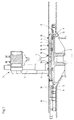
- a forging press 3 shown in FIG. 1 for reasons of better clarity with only one press stand 6, is adjustable in the direction of the double arrow (see FIGS. 3 and 4) Sliding table 4 arranged.
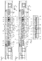
- the sliding table 4 lies flat on the table spar 2, as shown in the left half of Figure 2, and is secured by means of locking plates 5, 5 'against longitudinal displacement.
- the locking plates 5, 5 ' are along both longitudinal edges of the table spar 2 (see FIG. 2) and opposite, arranged in the sliding table 4 and locked into one another during forging, as shown in the right half of Figure 5.
- the locking plates 5, 5 ' are arranged on the mutually facing surfaces of the sliding table 4 and the table spar 2, namely the locking plates 5' in the sliding table 4 and the locking plates 5 in the table spar 2; they are offset from each other by a pitch T corresponding to the plate width.
- the detents could also consist, for example, of grooves in the table spar 2 and springs of the sliding table 4.
- the locking plates 5 and 5 ' are opposite the table spar 2 and the sliding table 4, and their long sides or edges are provided with inclined surfaces 19, with adjacent inclined surfaces of the upper and lower locking plates 5' and 5 when lowering the sliding table - or slide on each other and support the engagement of the upper locking plates 5 'in the gaps between the lower locking plates 5 of the table spar 2.
- the displacement table 4 carrying the tools is removed from its left half in FIG. 2 and in FIG. 3 shown position, in which it rests flat on the table spar 2, first raised hydraulically by means of roller units 8 until its locking plates 5 'are in one plane above the locking plates 5 of the table spar 2, as in the left half of Figure 5 and the right Half of Figure 2 shown.
- the roller units 8 are in cassette design executed (see FIGS. 3 and 4); in each cassette 9, two rollers 10 are encapsulated outwards and provided with permanent lubrication.
- transverse yoke 11 see the two roller units 8 shown in section in FIG. 3
- transverse yokes 11 are acted upon by actuating pistons 12, which are connected via lines 13 and an intermediate, multi-way valve 14 designed as a control valve to an unillustrated one Pressure medium source are connected.
- the lifted shifting table 4 is adjusted by means of a shifting cylinder 16 by a displacement distance corresponding to twice the pitch T, namely until the locking plates 5 'of the shifting table 4 are above one Gap between two locking plates 5 of the table spar 2 are reached, into which they snap when lowered, so that the upper and lower locking plates 5 'and 5 interlock.
- the table stroke or adjustment path (2 x pitch T) is determined by the width of the interchangeable locking plates 5, 5 'which can be variably adapted to the respective operating requirements.
- the rolling friction achieved when the displacement table 4 moves due to the raised rollers 10 of the roller units 8 makes it possible to dimension the displacement cylinder 16 much smaller than is the case with known forging presses with - also fast-wearing - tables to be displaced in guideways or slideways.
Landscapes
- Engineering & Computer Science (AREA)
- Mechanical Engineering (AREA)
- Forging (AREA)
- Saccharide Compounds (AREA)
Claims (8)
caractérisée
en ce que la table coulissante (4) est disposée sur un banc (2) de table présentant un transporteur à rouleaux (1) équipé de rouleaux (10) mobile en mouvement ascendant et descendant, et la table coulissante (4) et le banc (2) de la table sont munis, sur leurs surfaces qui sont dirigées l'une vers l'autre, de butées (5, 5′) qui s'imbriquent les unes dans les autres et qui sont décalées les unes par rapport aux autres d'un pas de division (T).
caractérisée
en ce que les butées sont des plaques (5, 5′) qui font saillie sur la table coulissante (4) ou sur le banc (2) de la table.
caractérisée
en ce que les plaques de butée (5, 5′) sont interchangeables.
caractérisée
en ce que les bords longitudinaux des butées (5, 5′) sont munis de surfaces obliques (19).
caractérisée
en ce que des rainures et languettes de la table coulissante (4) et du banc (2) de table forment les butées (5, 5′) .
caractérisée
en ce qu'au moins deux rouleaux (10) sont regroupés en une unité de rouleaux (8) enfermées sous carter.
caractérisée
par des rouleaux (10) munis d'une lubrification de longue durée.
caractérisée
par des conduites d'air comprimé (17) agencées au-dessous de la table coulissante (4).
Priority Applications (4)
| Application Number | Priority Date | Filing Date | Title |
|---|---|---|---|
| AT91108508T ATE76339T1 (de) | 1991-05-25 | 1991-05-25 | Schmiedepresse. |
| DE9191108508T DE59100001D1 (de) | 1991-05-25 | 1991-05-25 | Schmiedepresse. |
| ES199191108508T ES2033168T3 (es) | 1991-05-25 | 1991-05-25 | Prensa de forja. |
| EP91108508A EP0484623B1 (fr) | 1991-05-25 | 1991-05-25 | Presse à forger |
Applications Claiming Priority (1)
| Application Number | Priority Date | Filing Date | Title |
|---|---|---|---|
| EP91108508A EP0484623B1 (fr) | 1991-05-25 | 1991-05-25 | Presse à forger |
Publications (2)
| Publication Number | Publication Date |
|---|---|
| EP0484623A1 EP0484623A1 (fr) | 1992-05-13 |
| EP0484623B1 true EP0484623B1 (fr) | 1992-05-20 |
Family
ID=8206771
Family Applications (1)
| Application Number | Title | Priority Date | Filing Date |
|---|---|---|---|
| EP91108508A Expired - Lifetime EP0484623B1 (fr) | 1991-05-25 | 1991-05-25 | Presse à forger |
Country Status (4)
| Country | Link |
|---|---|
| EP (1) | EP0484623B1 (fr) |
| AT (1) | ATE76339T1 (fr) |
| DE (1) | DE59100001D1 (fr) |
| ES (1) | ES2033168T3 (fr) |
Families Citing this family (4)
| Publication number | Priority date | Publication date | Assignee | Title |
|---|---|---|---|---|
| DE4127237A1 (de) * | 1991-08-17 | 1993-02-18 | Schuler Gmbh L | Presse mit pressen- und schiebetisch |
| SE518669C2 (sv) * | 2001-03-13 | 2002-11-05 | Morphic Technologies Ab | Maskin för tillverkning av föremål |
| CN111819015B (zh) * | 2018-02-14 | 2022-06-07 | 日本精工株式会社 | 搬送系统、摆动锻造方法、摆动锻造装置、轴承的制造方法、车辆的制造方法、机械装置的制造方法 |
| US11959515B2 (en) | 2018-02-14 | 2024-04-16 | Nsk Ltd. | Conveying system, rotary forging method, rotary forging apparatus, method for manufacturing bearing, method for manufacturing vehicle, and method for manufacturing mechanical device |
Family Cites Families (3)
| Publication number | Priority date | Publication date | Assignee | Title |
|---|---|---|---|---|
| DE2161917C3 (de) * | 1971-12-14 | 1979-04-26 | Maschinenfabrik Weingarten Ag, 7987 Weingarten | Verfahrbare, sowie heb- und senkbare Werkzeugträgerplatte oder Schiebetisch für Pressen |
| DE2715782A1 (de) * | 1977-04-07 | 1978-10-19 | Ural Z Tjaschelogo Mash Im Ser | Vorrichtung zum anordnen eines werkzeuges auf dem ausfahrbaren tisch einer hydraulischen freiformschmiedepresse |
| CH667833A5 (en) * | 1985-04-09 | 1988-11-15 | Astrol S A | Machine tool pallet-changing mechanism - has pallet mounting bosses with self-centring action and securing clamps |
-
1991
- 1991-05-25 DE DE9191108508T patent/DE59100001D1/de not_active Expired - Lifetime
- 1991-05-25 ES ES199191108508T patent/ES2033168T3/es not_active Expired - Lifetime
- 1991-05-25 AT AT91108508T patent/ATE76339T1/de not_active IP Right Cessation
- 1991-05-25 EP EP91108508A patent/EP0484623B1/fr not_active Expired - Lifetime
Also Published As
| Publication number | Publication date |
|---|---|
| ATE76339T1 (de) | 1992-06-15 |
| ES2033168T3 (es) | 1993-03-01 |
| EP0484623A1 (fr) | 1992-05-13 |
| DE59100001D1 (de) | 1992-07-23 |
Similar Documents
| Publication | Publication Date | Title |
|---|---|---|
| DE2937972A1 (de) | Vorrichtung zum aufbringen einer flaechenpressung auf fortschreitende werkstuecke | |
| EP0231445A1 (fr) | Procédé et dispositif pour le déplacement horizontal des cylindres de laminage dans des cages de laminage | |
| EP1075943B1 (fr) | Machine d'impression | |
| EP0484623B1 (fr) | Presse à forger | |
| DE2453857C2 (de) | Arbeitswalzenwechselvorrichtung für ein Quartowalzgerüst zum Walzen von Blech | |
| DE9110487U1 (de) | Vorrichtung zum überlappenden Verschweißen von Folienrändern | |
| EP0483599B1 (fr) | Cage de laminoir comprenant des dispositifs pour supporter à distance le cylindre de travail supérieur | |
| DE4117185A1 (de) | Schmiedepresse | |
| DE4341431C2 (de) | Vorrichtung zum Klemmen und Spannen von biegsamen Druckplatten | |
| DE2224875C3 (de) | Vorrichtung zum Belasten und Trennen der Walzen eines der Bearbeitung von Bahnen, insbesondere von Papierbahnen, dienenden Walzensatzes | |
| DE2223150A1 (de) | Eintrittsfuehrung fuer bandwalzwerke | |
| DE3324562C2 (de) | Sechswalzengerüst | |
| DE2723432C3 (de) | Tischanschlag für eine Stanzmaschine | |
| DE8713454U1 (de) | Vorrichtung zum Walzen von Gewinden od. dgl. Profilen | |
| DE4122215C2 (de) | Vorrichtung zum automatischen Palettenwechsel | |
| DE3523944C2 (fr) | ||
| DE19937804A1 (de) | Druckwerk | |
| EP0114174A1 (fr) | Presse à manufacturer des cadres | |
| DE3811875A1 (de) | Fuehrungsvorrichtung | |
| DE2744529C3 (de) | Schweißmaschine zum elektrischen Widerstands-Stumpfschweißen | |
| DE4442567A1 (de) | Treibapparat für Walzband | |
| DE2003263A1 (de) | Transfereinrichtung zum gleichzeitigen Herausziehen mehrerer kontinuierlich gegossener Metallstraenge aus mehreren Giesskoepfen einer Stranggiessstation | |
| DE3918242A1 (de) | Vorrichtung zum distanzieren der walzen eines walzgeruests waehrend des walzenwechsels | |
| EP2195164A1 (fr) | Unité d'impression avec au moins deux parties latérales de bâti dont l'espacement mutuel en direction horizontale est variable | |
| DE2114736A1 (de) | Vorrichtung zur Ausübung einer Flächenpressung |
Legal Events
| Date | Code | Title | Description |
|---|---|---|---|
| ITF | It: translation for a ep patent filed | ||
| PUAI | Public reference made under article 153(3) epc to a published international application that has entered the european phase |
Free format text: ORIGINAL CODE: 0009012 |
|
| GRAA | (expected) grant |
Free format text: ORIGINAL CODE: 0009210 |
|
| 17P | Request for examination filed |
Effective date: 19910525 |
|
| AK | Designated contracting states |
Kind code of ref document: A1 Designated state(s): AT DE ES FR GB IT |
|
| AK | Designated contracting states |
Kind code of ref document: B1 Designated state(s): AT DE ES FR GB IT |
|
| REF | Corresponds to: |
Ref document number: 76339 Country of ref document: AT Date of ref document: 19920615 Kind code of ref document: T |
|
| REF | Corresponds to: |
Ref document number: 59100001 Country of ref document: DE Date of ref document: 19920723 |
|
| GBT | Gb: translation of ep patent filed (gb section 77(6)(a)/1977) | ||
| ET | Fr: translation filed | ||
| REG | Reference to a national code |
Ref country code: ES Ref legal event code: FG2A Ref document number: 2033168 Country of ref document: ES Kind code of ref document: T3 |
|
| PLBE | No opposition filed within time limit |
Free format text: ORIGINAL CODE: 0009261 |
|
| STAA | Information on the status of an ep patent application or granted ep patent |
Free format text: STATUS: NO OPPOSITION FILED WITHIN TIME LIMIT |
|
| 26N | No opposition filed | ||
| PGFP | Annual fee paid to national office [announced via postgrant information from national office to epo] |
Ref country code: FR Payment date: 19950426 Year of fee payment: 5 |
|
| PGFP | Annual fee paid to national office [announced via postgrant information from national office to epo] |
Ref country code: ES Payment date: 19950508 Year of fee payment: 5 |
|
| PGFP | Annual fee paid to national office [announced via postgrant information from national office to epo] |
Ref country code: DE Payment date: 19950512 Year of fee payment: 5 |
|
| PGFP | Annual fee paid to national office [announced via postgrant information from national office to epo] |
Ref country code: GB Payment date: 19950515 Year of fee payment: 5 |
|
| PGFP | Annual fee paid to national office [announced via postgrant information from national office to epo] |
Ref country code: AT Payment date: 19950522 Year of fee payment: 5 |
|
| PG25 | Lapsed in a contracting state [announced via postgrant information from national office to epo] |
Ref country code: GB Effective date: 19960525 Ref country code: AT Effective date: 19960525 |
|
| PG25 | Lapsed in a contracting state [announced via postgrant information from national office to epo] |
Ref country code: ES Free format text: LAPSE BECAUSE OF NON-PAYMENT OF DUE FEES Effective date: 19960527 |
|
| GBPC | Gb: european patent ceased through non-payment of renewal fee |
Effective date: 19960525 |
|
| PG25 | Lapsed in a contracting state [announced via postgrant information from national office to epo] |
Ref country code: FR Effective date: 19970131 |
|
| PG25 | Lapsed in a contracting state [announced via postgrant information from national office to epo] |
Ref country code: DE Effective date: 19970201 |
|
| REG | Reference to a national code |
Ref country code: FR Ref legal event code: ST |
|
| REG | Reference to a national code |
Ref country code: ES Ref legal event code: FD2A Effective date: 19990503 |
|
| PG25 | Lapsed in a contracting state [announced via postgrant information from national office to epo] |
Ref country code: IT Free format text: LAPSE BECAUSE OF NON-PAYMENT OF DUE FEES;WARNING: LAPSES OF ITALIAN PATENTS WITH EFFECTIVE DATE BEFORE 2007 MAY HAVE OCCURRED AT ANY TIME BEFORE 2007. THE CORRECT EFFECTIVE DATE MAY BE DIFFERENT FROM THE ONE RECORDED. Effective date: 20050525 |