EP0428096A1 - Vorrichtung zur Aufhängungsregelung - Google Patents
Vorrichtung zur Aufhängungsregelung Download PDFInfo
- Publication number
- EP0428096A1 EP0428096A1 EP90121596A EP90121596A EP0428096A1 EP 0428096 A1 EP0428096 A1 EP 0428096A1 EP 90121596 A EP90121596 A EP 90121596A EP 90121596 A EP90121596 A EP 90121596A EP 0428096 A1 EP0428096 A1 EP 0428096A1
- Authority
- EP
- European Patent Office
- Prior art keywords
- output signal
- vehicle
- detection means
- control apparatus
- bouncing
- Prior art date
- Legal status (The legal status is an assumption and is not a legal conclusion. Google has not performed a legal analysis and makes no representation as to the accuracy of the status listed.)
- Granted
Links
Images


Classifications
-
- B—PERFORMING OPERATIONS; TRANSPORTING
- B60—VEHICLES IN GENERAL
- B60G—VEHICLE SUSPENSION ARRANGEMENTS
- B60G17/00—Resilient suspensions having means for adjusting the spring or vibration-damper characteristics, for regulating the distance between a supporting surface and a sprung part of vehicle or for locking suspension during use to meet varying vehicular or surface conditions, e.g. due to speed or load
- B60G17/06—Characteristics of dampers, e.g. mechanical dampers
-
- B—PERFORMING OPERATIONS; TRANSPORTING
- B60—VEHICLES IN GENERAL
- B60G—VEHICLE SUSPENSION ARRANGEMENTS
- B60G17/00—Resilient suspensions having means for adjusting the spring or vibration-damper characteristics, for regulating the distance between a supporting surface and a sprung part of vehicle or for locking suspension during use to meet varying vehicular or surface conditions, e.g. due to speed or load
- B60G17/015—Resilient suspensions having means for adjusting the spring or vibration-damper characteristics, for regulating the distance between a supporting surface and a sprung part of vehicle or for locking suspension during use to meet varying vehicular or surface conditions, e.g. due to speed or load the regulating means comprising electric or electronic elements
- B60G17/016—Resilient suspensions having means for adjusting the spring or vibration-damper characteristics, for regulating the distance between a supporting surface and a sprung part of vehicle or for locking suspension during use to meet varying vehicular or surface conditions, e.g. due to speed or load the regulating means comprising electric or electronic elements characterised by their responsiveness, when the vehicle is travelling, to specific motion, a specific condition, or driver input
- B60G17/0165—Resilient suspensions having means for adjusting the spring or vibration-damper characteristics, for regulating the distance between a supporting surface and a sprung part of vehicle or for locking suspension during use to meet varying vehicular or surface conditions, e.g. due to speed or load the regulating means comprising electric or electronic elements characterised by their responsiveness, when the vehicle is travelling, to specific motion, a specific condition, or driver input to an external condition, e.g. rough road surface, side wind
-
- B—PERFORMING OPERATIONS; TRANSPORTING
- B60—VEHICLES IN GENERAL
- B60G—VEHICLE SUSPENSION ARRANGEMENTS
- B60G2400/00—Indexing codes relating to detected, measured or calculated conditions or factors
- B60G2400/10—Acceleration; Deceleration
- B60G2400/106—Acceleration; Deceleration longitudinal with regard to vehicle, e.g. braking
-
- B—PERFORMING OPERATIONS; TRANSPORTING
- B60—VEHICLES IN GENERAL
- B60G—VEHICLE SUSPENSION ARRANGEMENTS
- B60G2400/00—Indexing codes relating to detected, measured or calculated conditions or factors
- B60G2400/20—Speed
-
- B—PERFORMING OPERATIONS; TRANSPORTING
- B60—VEHICLES IN GENERAL
- B60G—VEHICLE SUSPENSION ARRANGEMENTS
- B60G2400/00—Indexing codes relating to detected, measured or calculated conditions or factors
- B60G2400/20—Speed
- B60G2400/204—Vehicle speed
-
- B—PERFORMING OPERATIONS; TRANSPORTING
- B60—VEHICLES IN GENERAL
- B60G—VEHICLE SUSPENSION ARRANGEMENTS
- B60G2500/00—Indexing codes relating to the regulated action or device
- B60G2500/10—Damping action or damper
-
- B—PERFORMING OPERATIONS; TRANSPORTING
- B60—VEHICLES IN GENERAL
- B60G—VEHICLE SUSPENSION ARRANGEMENTS
- B60G2600/00—Indexing codes relating to particular elements, systems or processes used on suspension systems or suspension control systems
- B60G2600/02—Retarders, delaying means, dead zones, threshold values, cut-off frequency, timer interruption
-
- B—PERFORMING OPERATIONS; TRANSPORTING
- B60—VEHICLES IN GENERAL
- B60G—VEHICLE SUSPENSION ARRANGEMENTS
- B60G2600/00—Indexing codes relating to particular elements, systems or processes used on suspension systems or suspension control systems
- B60G2600/70—Computer memory; Data storage, e.g. maps for adaptive control
-
- B—PERFORMING OPERATIONS; TRANSPORTING
- B60—VEHICLES IN GENERAL
- B60G—VEHICLE SUSPENSION ARRANGEMENTS
- B60G2800/00—Indexing codes relating to the type of movement or to the condition of the vehicle and to the end result to be achieved by the control action
- B60G2800/01—Attitude or posture control
- B60G2800/014—Pitch; Nose dive
-
- B—PERFORMING OPERATIONS; TRANSPORTING
- B60—VEHICLES IN GENERAL
- B60G—VEHICLE SUSPENSION ARRANGEMENTS
- B60G2800/00—Indexing codes relating to the type of movement or to the condition of the vehicle and to the end result to be achieved by the control action
- B60G2800/22—Braking, stopping
Definitions
- the present invention relates to a suspension control apparatus for controlling a vehicle posture by changing damping force of shockabsorber so as to decrease pitching motion of the vehicle during driving.
- the vehicle Immediately after a vehicle passes over a big projection of an uneven road, the vehicle receives a great shock from the projection in a vertical direction of the vehicle. This great shock received by the vehicle is called a bottoming motion. At this bottoming, that is, at the time of the bottoming motion, the driver and the fellow passenger feel the great shock. And, when the vehicle is driving on the very bumpy road, namely, the vehicle receives the shock continuously, road contact area of tyres decreases. The state that the vehicle receives the continuous shocks is called a bumpy-road driving. Therefore, when the vehicle is in the bumpy-road driving, it makes the driving stability and riding comfort poor.
- a conventional suspension control apparatus detects the pitching motion, that is the periodical vertical motion, the great shock or the continuous shock in vertical direction, by inferring from change of the vehicle height or change of stroke of shockabsorbers. Then, damping force of the shockabsorbers for restraining the pitching motion are controlled, by signals in response to the change of the vehicle height or change of stroke of the shockabsorbers during driving on the undulated surface road, the uneven road or the very bumpy road.
- the above-mentioned conventional suspension control apparatus provides a brake switch which detects the braking whether a brake is operated by a driver or not.
- the brake switch When the brake switch is in ON-state, the conventional suspension control apparatus judges that the vehicle is in braking, and controls to increase the damping force of the shockabsorbers.
- the pitching motion of the vehicle namely, the nose-diving motion of the vehicle during braking, is restrained by such conventional suspension control apparatus.
- the distance measuring instrument e.g. ultra-sonic sensors
- the ultra-sonic sensors are mounted on the vehicle body near the road surface. Therefore, the ultra-sonic sensors are liable to be covered with mud, dust or snow. As a result, the ultra-sonic sensors will make malfunction. Even if the ultra-sonic sensors is operated in clean state, output signals from the ultra-sonic sensors may show an incorrect vehicle posture, because the output signals of it show the only interval between the road surface and the part of vehicle body where the ultra-sonic sensor is just mounted.
- such suspension control apparatus may make a false determination that the vehicle is in braking when the brake pedal is touched by the foot of the driver even slightly.
- the brake pedal generally has a playing interval at its early stroke, there is a case that the vehicle is not in the real braking even if the brake switch is in ON-state. Therefore, the damping force of the shockabsorber is wrongly controlled when there is no nose-diving motion of the vehicle. In such case, the riding comfort becomes worse because of wrong controlling of the damping force.
- the Japanese published unexamined patent application No. Sho 63-68413 discloses another conventional suspension control apparatus having a vehicle speed sensor and three angular velocity sensors for directly detecting a vehicle motion behavior.
- the three angular velocity sensors detect a yaw angular velocity, a pitch angular velocity and a roll angular velocity. Thereby the vehicle behavior is grasped and the damping force of the shockabsorber is controlled in response to the vehicle behavior.
- the above-mentioned yaw angular velocity is an angular velocity in a rotation about vertical line (yaw axis) at a center of the vehicle.
- the pitch angular velocity is an angular velocity in a rotation about a lateral axis (pitch axis) of the vehicle.
- the roll angular velocity is an angular velocity in a rotation about a longitudinal axis (roll axis) of the vehicle.
- This conventional suspension control apparatus which is for controlling to decrease a rolling motion of the vehicle behavior by using these signals from three angular velocity sensors, has the following problems.
- An arithmetic unit of the suspension control apparatus carries out a complicated computing by using three output signals of the yaw angular velocity sensor, the pitch angular velocity sensor and the roll angular velocity sensor. Therefore, this suspension control apparatus needs a considerable time for computing these data.
- the operation time for computation of a control signal namely, the time period from reception of detection signals the arithmetic unit to issuance of output signal to the actuators takes about 20 msec.
- the apparatus having the CPU of 8 bit can not control in response to a sharp or quick pitching motion during driving. Therefore, the conventional suspension control apparatus necessitates to use a higher speed CPU as the arithmetic unit, such as a CPU of 16 bit for controlling to decrease such pitching motion.
- a higher speed CPU such as a CPU of 16 bit for controlling to decrease such pitching motion.
- to use such high speed CPU in the vehicle unduly increases the manufacturing cost of the vehicle.
- An object of the present invention is to provide a suspension control apparatus which can achieve a high stability of a vehicle behavior and at the same time an improved ride comfort of the vehicle at bouncing, bottoming, and at bumpy-road driving or braking, without increase of manufacturing cost.
- the suspension control apparatus of the present invention comprises: a vehicle speed sensor for detecting speed of a vehicle, a pitch angular velocity sensor for detecting angular velocity about a pitch axis of the vehicle, bouncing detection means which detects bouncing of the vehicle by an output signal of the vehicle speed sensor and an output signal of the pitch angular velocity sensor, bottoming detection means which detects bottoming of the vehicle by the output signal of the vehicle speed sensor and the output signal of the pitch angular velocity sensor, bumpy-road drive detection means which detects bumpy-road driving of the vehicle by the output signal of the pitch angular velocity sensor, a brake switch which detects whether a brake pedal is depressed or not, braking detection means which detects braking of the vehicle by an output signal of the brake switch and the output signal of the pitch angular velocity sensor, and shockabsorber means whereof damping force is adjusted in response to output signal from the bouncing detection means, the bottoming detection means, the bumpy-road drive detection
- the suspension control apparatus of the present invention In accordance with the suspension control apparatus of the present invention, bouncing, bottoming, bumpy-road driving and braking of the vehicle are detected by output signals of the vehicle speed sensor and the pitch angular velocity sensor. Therefore, the suspension control apparatus of the present invention does not have malfunction by mud, dust or snow on the road in case of measuring vehicle height with the above-mentioned ultrasonic sensor. And the vehicle posture change can correctly detected. Furthermore, the suspension control apparatus of the present invention does not have malfunction due to the abrasion of the sliding part e.g. variable resistor used for detecting stroke of the shockabsorber.
- FIG.1 is a perspective view showing a principal part of the suspension control apparatus which is disposed in a vehicle 11 shown with alternate long and short dash line.
- the suspension control apparatus comprises a vehicle speed sensor 1, a pitch angular velocity sensor 2, shockabsorbers 3, actuators 4, a brake switch 5 and a controller 6.
- the vehicle speed sensor 1, which is disposed in a front grill adjacent a speed meter, produces a signal of vehicle speed by detecting the revolution speed of an output shaft of a gearbox in the vehicle 11.
- the pitch angular velocity sensor 2 is provided to detect an angular velocity of rotation about a lateral line of vehicle body at substantially a center of the vehicle 11, that is about a pitch axis B of the vehicle 11. The directions of the rotation are shown with arrow A in FIG.1.
- the pitch angular velocity sensor 2 for instance described in U.S. Pat. No. 4,671,112, which is issued June 9, 1987 and granted to the same assignee, is usable.
- the shockabsorbers 3 damp the force received by wheels of the vehicle 11.
- the actuators 4, which are provided on the shockabsorbers 3, control the damping force of these shockabsorbers 3.
- the brake switch 5, which operates with ON/OFF control action, detects whether a brake pedal is operated by a driver or not.
- the controller 6, which is disposed in appropriate space, such as under the back seat or in the trunk, produces the output signal for controlling the damping force of the shockabsorbers 3.
- the actuator 4 operates the shockabsorber 3 by receiving the signal, which is produced by the controller 6 in response to the output signals of the vehicle speed sensor 1, the pitch angular velocity sensor 2 and the brake switch 5.
- the shockabsorber 3 is a hydraulic active suspension and its damping rate is controlled by controlling hydraulic values by electromagnet.
- FIG.2 is a graph of a typical output signal ⁇ p of a pitch angular velocity sensor 2 when the vehicle 11 makes periodical motion, that is, when the vehicle 11 makes the bouncing. And, FIG.2 shows the method how the bouncing is inferred or estimated from the output signal ⁇ p of the pitch angular velocity sensor 2.
- a period T ⁇ of the output signal ⁇ p output from the pitch angular velocity sensor 2 is within a predetermined time range t c , and further an absolute value
- the bouncing is the state of the conditions shown by the following formulas (1) and (2): Tm - t c ⁇ T ⁇ ⁇ Tm (1),
- Table 1 below shows the map for the bouncing detection part 7 of the controller 6, and the abovementioned bouncing reference value ⁇ BOU is decided by retrieving the map (table 1) by using as address the output signal V of the vehicle speed sensor 1.
- the bouncing reference value ⁇ BOU1, ⁇ BOU2, or ⁇ BOU5 decided by the map is used as criterion in judgment for bottoming in variable speed V1 -- V6 of the vehicle.
- Table 1 Vehicle speed V1 -- V2 V2 -- V3 V3 -- V4 V4 -- V5 V5 -- V6 amplitude of ⁇ p ⁇ BOU1 ⁇ BOU2 ⁇ BOU3 ⁇ BOU4 ⁇ BOU5
- Table 2 below shows the operating parameters which are found preferable through experiments.
- the period T ⁇ of the output signal ⁇ p is set up to satisfy the following inequity (3): 0.5 sec. ⁇ T ⁇ ⁇ 1 sec. (3).
- Table 2 Vehicle speed (km/h) 0 km/h or more -- below 20 km/h 20 km/h or more -- below 40 km/h 40 km/h or more -- below 60 km/h 60 km/h or more -- below 80 km/h 80 km/h or more ⁇ BOU (deg/sec) 4.5 4.0 3.5 3.0 3.0
- a modified embodiment may be such that the reference value ⁇ BOU is set constant.
- FIG.3 is a graph of a typical output signal wp of the pitch angular velocity sensor 2 when the vehicle receives a great shock, that is, when the vehicle 11 enters the bottoming. And, FIG.3 shows the method how the bottoming is inferred or estimated from the output signal wp of the pitch angular velocity sensor 2, and the time when the shockabsorbers 3 are controlled by the controller 6.
- FIG. 3 when the absolute value
- the bottoming is the state of the conditions shown by the following formula (4):
- Table 3 below shows the map for the bottoming detection part 8 of the controller 6.
- the above-mentioned bottoming reference value ⁇ BOT is decided by retrieving the map (table 3) by using output signal V of the vehicle speed sensor 1.
- the bottoming reference value ⁇ BOT1, ⁇ BOT2, ⁇ or ⁇ BOT5 decided by the map is used as criterion in judgment for bottoming in various speeds V1 -- V6 of the vehicle 11.
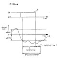
- FIG.4 is a graph of a typical output signal wp of the pitch angular velocity sensor 2 when the vehicle 11 is braked, that is, the vehicle 11 is in braking. And, FIG.4 shows how the braking is inferred or estimated from the output signal ⁇ p of the pitch angular velocity sensor 2 and an output signal S of the brake switch 5. As shown in FIG.4, when the brake switch 5 is turned to ON-state and further the absolute value
- the state of braking is judged when the conditions is shown by the following formula (5) and when the brake switch 5 is in ON-state:
- the following formula (6) shows the preferable operation parameters for judging the braking:
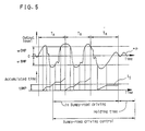
- FIG.5 is a graph of a typical output signal ⁇ p of the pitch angular velocity sensor 2 when the vehicle 11 is driven on the very bumpy road, that is, the vehicle 11 receives the continuous shocks. And, FIG.5 shows how the bumpy-road driving is inferred from the output signal ⁇ p of the pitch angular velocity sensor 2.
- Ta are constant times, e.g. 1.5 second.
- Ts is a time period defined by accumulating respective time periods when the absolute value
- FIG.6 shows the block diagram of the suspension control apparatus of the present invention in FIG.1.
- the controller 6 provides the bouncing detection part 7 for detecting the bouncing, the bottoming detection part 8 for detecting bottoming, the braking detection part 9 for detecting braking, the bumpy-road drive detection part 10 for detecting bumpy-road driving and the operation circuit 21 for driving the actuator 4.
- the controller 6 is constituted substantially by an A/D converter, an arithmetic unit, such as a logical circuit having a CPU, a ROM and a RAM.
- the bouncing detection part 7 decides the aforementioned bouncing reference value ⁇ BOU, which is for judging the output signal ⁇ p of the pitch angular velocity sensor 2, by retrieving the map (table 1) with the output signal V of the vehicle speed sensor 1.
- ⁇ BOU aforementioned bouncing reference value
- the bottoming detection part 8 decides the aforementioned bottoming reference value ⁇ BOT, which is for judging the output signal ⁇ p of the pitch angular velocity sensor 2, by retrieving the map (table 3) with the output signal V of the vehicle sensor 1.
- the amplitude of the output signal ⁇ p reaches or exceeds the bottoming reference value ⁇ BOT, the bottoming detection part 8 judges that the vehicle 11 is in bottoming as shown in FIG.3.
- the bottoming detection part 8 produces an output signal to the operation circuit 21, which is for controlling the shockabsorbers 3 to decrease the bottoming motion received by the vehicle 11. That is, the suspension control apparatus of the invention carries out the bottoming control for the time period designated in FIG.3 by the words "bottoming control".
- the braking detection part 9 infers whether the brake pedal is only touched by a foot of a driver or depressed for braking in practice, from the AND signal of the output signal S of the brake switch 5 and the output signal ⁇ p of the pitch angular velocity sensor 2. If the vehicle 11 is in braking, that is, the brake pedal is operated to decrease the vehicle speed, the braking detection part 9 produces an output signal to the operation circuit 21, thereby to control the shockabsorbers 3 to restrain the nose-diving motion caused by braking.
- the bumpy-road drive detection part 10 detects the bumpy-road driving of the vehicle 11 by using the output signal ⁇ p of the pitch angular velocity sensor 2, as shown in FIG.5.
- the bumpy-road drive detection part 10 produces an output signal to the operation circuit 21 for controlling the vehicle posture, to improve the driving stability and riding comfort.
- the operation circuit 21 receives the output signal from the bouncing detection part 7, the bottoming detection part 8, the braking detection part 9 or the bumpy-road drive detection part 10. As a result, the operation circuit 21 drives the actuators 4 to change a predetermined damping rate for the damping force of the shockabsorbers 3.
- a modified embodiment may be such that the shockabsorbers are controlled to change the damping rate in response to each bouncing, bottoming, bumpy-road driving or braking.
- table 5 shows the operating parameter for controlling the shockabsorbers in response to bouncing, bottoming, bumpy-road driving or braking.
- table 5 normal driving bouncing bottoming braking bumpy-road driving damping rate 0.2 0.63 0.57 0.6 0.4
- the damping rate in table 5 is given by the following formula (9): where C is the damping coefficient of the shockabsorber 3 during normal straight driving of the vehicle 11, M is the sprung mass and K is the spring constant (SI units: N m ) of the suspension.
- FIG.7 shows a characteristic diagram of the holding time T for retaining the damping force after completion of bouncing, bottoming, braking or bumpy-road driving.
- the holding time T is not set up, the damping force of the shockabsorber 3 will be frequently changed. As a result, the driving stability and riding comfort become worse by frequent changes of the damping force. Therefore, the vehicle 11 needs retention of the damping force of the shockabsorbers 3 for at least a predetermined holding time T after either of bouncing, bottoming, braking or bumpy-road driving as in FIG.2, 3, 4 or 5 has been finished.
- the holding time T in which the increased damping force is retained is to be set the shorter as the vehicle speed becomes the higher. And, when the vehicle speed is above 80 km/h, the holding time T is set up to be constant, such as at 1.0 sec, as shown in FIG.7. This setting of the operation parameters are experimentally found preferable.
- a modified embodiment may be such that the holding time T is set up constant, or alternatively is set up so as to respond to the displacement length (distance) of the vehicle 11 after finish of the bouncing, the bottoming, the braking or the bumpy-road driving.
- the holding time T may be set up to become the larger as the vehicle speed is the faster.
- FIG.8 shows a flow chart of operation of the controller 6 of the suspension control apparatus of the present invention.
- step 101 of FIG. 8 the output signal V from the vehicle speed sensor 1, the output signal ⁇ p from the pitch angular velocity sensor 2 and the output signal S from the brake switch 5 are detected.
- step 102 it is judged whether the vehicle 11 is in bouncing or not. That is, it is judged that whether the vehicle 11 is in bouncing or not, under the condition shown by the aforementioned formulas (1) and (2).
- the suspension control apparatus controls to increase the damping force of the shockabsorbers 3 in step 103.
- step 104 When the controller 6 in step 102 decides "NO", that is, the vehicle 11 is not in bouncing, it is judged whether the vehicle 11 is in bottoming or not, in step 104. Namely, when the condition is as shown by the aforementioned formula (4), it is judged that the vehicle 11 is in bottoming.
- the suspension control apparatus controls to increase the damping force of the shockabsorbers 3 in step 105.
- step 106 When the controller 6 in step 104 decides "NO", that is, the vehicle 11 is not in bottoming, it is judged whether the vehicle 11 is in bumpy-road driving or not, in step 106. Namely, when the aforementioned absolute value
- the suspension control apparatus controls to increase the damping force of the shockabsorbers 3 in step 107 in order to enlarge the road contact area of the tire and to improve the riding comfort. As a result, the driving stability in the vehicle 11 is assured even if the vehicle 11 is driven on very bumpy-road.
- step 106 When the controller 6 in step 106 decides "NO", that is, the vehicle 11 is not on bumpy-road, it is judged whether the vehicle 11 is in braking or not, in step 108. Namely, when the condition is shown by the aforementioned formula (5) and the brake switch 5 is in ON-state, it is judged that the vehicle 11 is in braking.
- the suspension control apparatus controls to increase the damping force of the shockabsorbers 3 in 109, to restrain the nosediving motion during the braking.
- step 108 when the controller 6 in step 108 decides "NO", that is, the vehicle 11 is not in braking, the controller 6 judges whether the shockabsorbers 3 have been controlled or not in step 110.
- the controller 6 in step 110 decides "YES”, that is, it is judged that bouncing, bottoming, bumpy-road driving or braking have finished
- a suitable holding time T (which is the time wherein the damping force is controlled after bouncing, bottoming, bumpy-road driving or braking) is decided in response to the output signal V from the vehicle speed sensor 1 in step 111, as has been aforementioned in reference to the waveform shown in FIG. 7.
- step 112 the controlled damping force of the shockabsorbers 3 are kept for the holding time T after these state have been finished.
- the shockabsorbers 3 After holding the damping force of the shockabsorbers 3 for the holding time T, the shockabsorbers 3 become to normal damping force which lasts until the suspension control apparatus detects next bouncing, bottoming, bumpy-road driving or braking.
- step 110 when the controller 6 judges that the shockabsorbers 3 have not yet 0 been controlled to increase the damping force for bouncing, bottoming, bumpy-road driving or braking, the shockabsorbers 3 are kept in normal condition continuously.
- the time required for computing of the controller 6 is short, since the controller 6 carries out a simple computing by using the output signals of the vehicle speed sensor 1, the brake switch 5 and the only one angular velocity sensor.
- the operation times for computation of a control signal namely the time period from reception of detection signals the arithmetic unit to issuance of output signal to the actuators 4 takes about only 5 msec.
- the suspension control apparatus of the present invention can timely and effectively control the damping force to increase in response to a rotation around the pitch axis B of the vehicle 11 when the vehicle 11 is driven on the undulated surface road, big uneven surface road or very bumpy-road.
- the driving stability and riding comfort are assured by omission of too frequent changes of the damping force at successive occurrences of various types of road conditions, since the suspension control apparatus of the present invention keeps to control the damping force of the shockabsorbers 3 after the bouncing, bottoming, bumpy-road driving or braking has been finished.
Landscapes
- Engineering & Computer Science (AREA)
- Mechanical Engineering (AREA)
- Vehicle Body Suspensions (AREA)
Applications Claiming Priority (10)
| Application Number | Priority Date | Filing Date | Title |
|---|---|---|---|
| JP1294508A JPH03157212A (ja) | 1989-11-13 | 1989-11-13 | サスペンション制御装置 |
| JP294508/89 | 1989-11-13 | ||
| JP325064/89 | 1989-12-14 | ||
| JP1325064A JPH03186415A (ja) | 1989-12-14 | 1989-12-14 | サスペンション制御装置 |
| JP100013/90 | 1990-04-16 | ||
| JP2100011A JPH042512A (ja) | 1990-04-16 | 1990-04-16 | サスペンション制御装置 |
| JP100011/90 | 1990-04-16 | ||
| JP2100013A JPH042514A (ja) | 1990-04-16 | 1990-04-16 | サスペンション制御装置 |
| JP109028/90 | 1990-04-25 | ||
| JP2109028A JPH048616A (ja) | 1990-04-25 | 1990-04-25 | サスペンション制御装置 |
Publications (2)
| Publication Number | Publication Date |
|---|---|
| EP0428096A1 true EP0428096A1 (de) | 1991-05-22 |
| EP0428096B1 EP0428096B1 (de) | 1996-01-31 |
Family
ID=27525987
Family Applications (1)
| Application Number | Title | Priority Date | Filing Date |
|---|---|---|---|
| EP90121596A Expired - Lifetime EP0428096B1 (de) | 1989-11-13 | 1990-11-12 | Vorrichtung zur Aufhängungsregelung |
Country Status (6)
| Country | Link |
|---|---|
| US (1) | US5127667A (de) |
| EP (1) | EP0428096B1 (de) |
| KR (1) | KR940002587B1 (de) |
| CA (1) | CA2029709C (de) |
| DE (1) | DE69025131T2 (de) |
| ES (1) | ES2085311T3 (de) |
Cited By (6)
| Publication number | Priority date | Publication date | Assignee | Title |
|---|---|---|---|---|
| EP0465849A2 (de) * | 1990-06-15 | 1992-01-15 | Matsushita Electric Industrial Co., Ltd. | Vorrichtung zur Aufhängungsregelung |
| DE4119323A1 (de) * | 1991-06-12 | 1992-12-17 | Bilstein August Gmbh Co Kg | Verfahren zur frequenzabhaengigen adaptiven regelung eines fahrwerks |
| FR2798321A1 (fr) * | 1999-08-05 | 2001-03-16 | Toyota Motor Co Ltd | Dispositif pour controler des amortisseurs de suspension de vehicules a l'aide de substituts virtuels places en biais |
| FR2832102A1 (fr) * | 2001-11-13 | 2003-05-16 | Volkswagen Ag | Procede de reglage d'amortisseurs |
| WO2015080652A1 (en) * | 2013-11-29 | 2015-06-04 | BAE Systems Hägglunds Aktiebolag | Nose-dive reducing suspension lock arrangement for motor vehicle |
| WO2018024612A1 (en) * | 2016-08-04 | 2018-02-08 | Jaguar Land Rover Limited | A system for use in a vehicle |
Families Citing this family (20)
| Publication number | Priority date | Publication date | Assignee | Title |
|---|---|---|---|---|
| GB2239506B (en) * | 1989-12-08 | 1993-08-25 | Toyota Motor Co Ltd | Suspension control system |
| DE4112005A1 (de) * | 1991-04-12 | 1992-10-15 | Bosch Gmbh Robert | System zur bildung eines signals bei einem fahrzeug |
| DE4115481C2 (de) * | 1991-05-11 | 2001-04-19 | Bosch Gmbh Robert | System zur Erhöhung des Fahrkomforts und der Fahrsicherheit |
| WO1996005975A1 (en) * | 1994-08-18 | 1996-02-29 | Aimrite Systems International, Inc. | Computer optimized adaptive suspension system and method improvements |
| JPH09175137A (ja) * | 1995-12-26 | 1997-07-08 | Unisia Jecs Corp | 車両懸架装置 |
| JP2000512947A (ja) * | 1996-06-24 | 2000-10-03 | ブリード オートモティブ テクノロジィ,インク. | 乗物安全装置用制御装置 |
| DE69727225T2 (de) * | 1996-06-24 | 2004-10-21 | Breed Automotive Tech | Kraftstofffluss-steuerungseinheit |
| WO2000027658A1 (en) * | 1998-11-11 | 2000-05-18 | Kenmar Company Trust | Suspension control unit and control valve |
| US20040111707A1 (en) * | 2000-12-15 | 2004-06-10 | Bliss Andrew L. | Debugger for multiple processors and multiple debugging types |
| US7066474B2 (en) * | 2003-03-14 | 2006-06-27 | Valid Manufacturing Ltd. | Electronic suspension and level control system for recreational vehicles |
| JP4375161B2 (ja) * | 2004-08-18 | 2009-12-02 | 株式会社豊田中央研究所 | 車両安定化制御装置 |
| US8160774B2 (en) * | 2008-10-15 | 2012-04-17 | GM Global Technology Operations LLC | Vehicular actuator system |
| US8174377B2 (en) * | 2008-11-14 | 2012-05-08 | GM Global Technology Operations LLC | Suspension height sensor |
| US8175770B2 (en) * | 2008-11-17 | 2012-05-08 | GM Global Technology Operations LLC | Height sensing system for a vehicular suspension assembly |
| US8143766B2 (en) * | 2009-02-27 | 2012-03-27 | GM Global Technology Operations LLC | Harvesting energy from vehicular vibrations using piezoelectric devices |
| US8063498B2 (en) * | 2009-02-27 | 2011-11-22 | GM Global Technology Operations LLC | Harvesting energy from vehicular vibrations |
| US8253281B2 (en) * | 2009-02-27 | 2012-08-28 | GM Global Technology Operations LLC | Energy harvesting apparatus incorporated into shock absorber |
| JP4927919B2 (ja) * | 2009-09-16 | 2012-05-09 | 日立オートモティブシステムズ株式会社 | 車両制御装置 |
| US8614518B2 (en) * | 2009-10-14 | 2013-12-24 | GM Global Technology Operations LLC | Self-powered vehicle sensor systems |
| US20230086480A1 (en) * | 2021-09-17 | 2023-03-23 | Rivian Ip Holdings, Llc | Active suspension damping |
Citations (2)
| Publication number | Priority date | Publication date | Assignee | Title |
|---|---|---|---|---|
| EP0166313A2 (de) * | 1984-06-14 | 1986-01-02 | Nissan Motor Co., Ltd. | Aufhängungsregelungsvorrichtung für ein Kraftfahrzeug zum Verhindern des Rücksprunges |
| GB2215287A (en) * | 1988-03-08 | 1989-09-20 | Yazaki Corp | Actively controlled vehicle shock absorbers |
Family Cites Families (7)
| Publication number | Priority date | Publication date | Assignee | Title |
|---|---|---|---|---|
| GB1555124A (en) * | 1975-06-07 | 1979-11-07 | Lucas Industries Ltd | Vehicle suspension systems |
| FR2558778B1 (fr) * | 1984-01-24 | 1988-04-29 | Mitsubishi Motors Corp | Appareil de suspension de vehicule |
| DE3414257C2 (de) * | 1984-04-14 | 1993-12-02 | Bosch Gmbh Robert | Federelement mit veränderbarer Härte für Fahrzeuge |
| DE3434660A1 (de) * | 1984-09-21 | 1986-04-03 | Fa. Carl Freudenberg, 6940 Weinheim | Luftfeder |
| JPS6368413A (ja) * | 1986-09-09 | 1988-03-28 | Yazaki Corp | 車両走行安定制御装置 |
| JPS63166614A (ja) * | 1986-12-26 | 1988-07-09 | Toyota Motor Corp | サスペンシヨンの制御装置 |
| JPH01202511A (ja) * | 1988-02-05 | 1989-08-15 | Nissan Motor Co Ltd | サスペンション装置 |
-
1990
- 1990-11-09 CA CA002029709A patent/CA2029709C/en not_active Expired - Fee Related
- 1990-11-12 EP EP90121596A patent/EP0428096B1/de not_active Expired - Lifetime
- 1990-11-12 ES ES90121596T patent/ES2085311T3/es not_active Expired - Lifetime
- 1990-11-12 DE DE69025131T patent/DE69025131T2/de not_active Expired - Fee Related
- 1990-11-13 US US07/611,802 patent/US5127667A/en not_active Expired - Fee Related
- 1990-11-13 KR KR1019900018327A patent/KR940002587B1/ko not_active IP Right Cessation
Patent Citations (2)
| Publication number | Priority date | Publication date | Assignee | Title |
|---|---|---|---|---|
| EP0166313A2 (de) * | 1984-06-14 | 1986-01-02 | Nissan Motor Co., Ltd. | Aufhängungsregelungsvorrichtung für ein Kraftfahrzeug zum Verhindern des Rücksprunges |
| GB2215287A (en) * | 1988-03-08 | 1989-09-20 | Yazaki Corp | Actively controlled vehicle shock absorbers |
Non-Patent Citations (2)
| Title |
|---|
| PATENT ABSTRACTS OF JAPAN vol. 12, no. 432 (M-763)(3279) 15 November 1988, & JP-A-63 166614 (TOYOTA MOTOR CORP) 9 July 1988, * |
| PATENT ABSTRACTS OF JAPAN vol. 13, no. 500 (M-891)(3848) 10 November 1989, & JP-A-1 202511 (NISSAN MOTOR CO LTD) 15 August 1989, * |
Cited By (10)
| Publication number | Priority date | Publication date | Assignee | Title |
|---|---|---|---|---|
| EP0465849A2 (de) * | 1990-06-15 | 1992-01-15 | Matsushita Electric Industrial Co., Ltd. | Vorrichtung zur Aufhängungsregelung |
| EP0465849A3 (en) * | 1990-06-15 | 1992-06-03 | Matsushita Electric Industrial Co., Ltd. | Suspension control apparatus |
| US5161816A (en) * | 1990-06-15 | 1992-11-10 | Matsushita Electric Industrial Co., Ltd. | Suspension control apparatus |
| DE4119323A1 (de) * | 1991-06-12 | 1992-12-17 | Bilstein August Gmbh Co Kg | Verfahren zur frequenzabhaengigen adaptiven regelung eines fahrwerks |
| FR2798321A1 (fr) * | 1999-08-05 | 2001-03-16 | Toyota Motor Co Ltd | Dispositif pour controler des amortisseurs de suspension de vehicules a l'aide de substituts virtuels places en biais |
| FR2832102A1 (fr) * | 2001-11-13 | 2003-05-16 | Volkswagen Ag | Procede de reglage d'amortisseurs |
| WO2015080652A1 (en) * | 2013-11-29 | 2015-06-04 | BAE Systems Hägglunds Aktiebolag | Nose-dive reducing suspension lock arrangement for motor vehicle |
| US10131386B2 (en) | 2013-11-29 | 2018-11-20 | BAE Systems Hägglunds Aktiebolag | Nose-dive reducing suspension lock arrangement for motor vehicle |
| WO2018024612A1 (en) * | 2016-08-04 | 2018-02-08 | Jaguar Land Rover Limited | A system for use in a vehicle |
| US11560032B2 (en) | 2016-08-04 | 2023-01-24 | Jaguar Land Rover Limited | System and method for determining whether to adjust the ride height of a vehicle |
Also Published As
| Publication number | Publication date |
|---|---|
| DE69025131T2 (de) | 1996-09-19 |
| US5127667A (en) | 1992-07-07 |
| ES2085311T3 (es) | 1996-06-01 |
| DE69025131D1 (de) | 1996-03-14 |
| EP0428096B1 (de) | 1996-01-31 |
| CA2029709A1 (en) | 1991-05-14 |
| KR910009481A (ko) | 1991-06-28 |
| CA2029709C (en) | 1994-04-19 |
| KR940002587B1 (ko) | 1994-03-26 |
Similar Documents
| Publication | Publication Date | Title |
|---|---|---|
| EP0428096B1 (de) | Vorrichtung zur Aufhängungsregelung | |
| US4905783A (en) | Vehicular controller with differential wheel speed input | |
| EP0492782B1 (de) | Vorrichtung und Methode zur dynamischen Ermittlung der Zentripetalkraft einer Fahrzeugs | |
| EP0672548A2 (de) | Vorrichtung und Verfahren zum Regeln der Dämpfungscharakteristiken von Fahrzeugstossdämpfern | |
| US6202011B1 (en) | Electronic controlled suspension system using wheel speed | |
| GB2406548A (en) | Air suspension system | |
| EP0752330A2 (de) | Steuerung für eine Radaufhängung eines Kraftfahrzeugs | |
| KR19980031243A (ko) | 차량의 반 능동 전자 제어 현가 장치 및 방법 | |
| EP0465849B1 (de) | Vorrichtung zur Aufhängungsregelung | |
| JPH02270619A (ja) | ショックアブソーバ制御装置 | |
| EP0769396A3 (de) | Kraftfahrzeug-Aufhängungssteuervorrichtung | |
| EP1391330A2 (de) | Aufhängungsvorrichtung zur Begrenzung des Wankens oder des Gierens für Fahrzeuge | |
| EP0296756B1 (de) | Steuersystem für ein Fahrzeug mit der Drehzahldifferenz der Räder als Eingangssignal | |
| JP2946511B2 (ja) | ショックアブソーバの減衰力制御装置 | |
| US5163704A (en) | Control apparatus of support unit | |
| EP0424843B1 (de) | Aufhängungsregelvorrichtung | |
| JPH08310214A (ja) | 車両のサスペンション制御装置 | |
| KR100820412B1 (ko) | 자동차 전자제어식 현가장치의 제어방법 | |
| EP0678406B1 (de) | Automatisches System zur Veränderung der Aufhängungssteifigkeit und/oder Dämpfung eines Kraftfahrzeuges | |
| US6234492B1 (en) | Method and system for providing variable load control and isolation in a vehicle suspension | |
| KR100209090B1 (ko) | 악로 주행 판단 기능을 갖는 자동 서스펜션 시스템 | |
| JP2002005657A (ja) | 車体の傾斜角度検出方法 | |
| KR19980038769U (ko) | 운전석 지지장치 | |
| KR100241376B1 (ko) | 차량 반능동 현가의 감쇠력 결정방법 | |
| JP3327037B2 (ja) | 車両のサスペンション制御装置 |
Legal Events
| Date | Code | Title | Description |
|---|---|---|---|
| PUAI | Public reference made under article 153(3) epc to a published international application that has entered the european phase |
Free format text: ORIGINAL CODE: 0009012 |
|
| 17P | Request for examination filed |
Effective date: 19901112 |
|
| AK | Designated contracting states |
Kind code of ref document: A1 Designated state(s): DE ES FR GB IT |
|
| 17Q | First examination report despatched |
Effective date: 19921103 |
|
| GRAA | (expected) grant |
Free format text: ORIGINAL CODE: 0009210 |
|
| AK | Designated contracting states |
Kind code of ref document: B1 Designated state(s): DE ES FR GB IT |
|
| ITF | It: translation for a ep patent filed |
Owner name: JACOBACCI & PERANI S.P.A. |
|
| REF | Corresponds to: |
Ref document number: 69025131 Country of ref document: DE Date of ref document: 19960314 |
|
| ET | Fr: translation filed | ||
| REG | Reference to a national code |
Ref country code: ES Ref legal event code: FG2A Ref document number: 2085311 Country of ref document: ES Kind code of ref document: T3 |
|
| PGFP | Annual fee paid to national office [announced via postgrant information from national office to epo] |
Ref country code: GB Payment date: 19961104 Year of fee payment: 7 |
|
| PGFP | Annual fee paid to national office [announced via postgrant information from national office to epo] |
Ref country code: FR Payment date: 19961111 Year of fee payment: 7 |
|
| PGFP | Annual fee paid to national office [announced via postgrant information from national office to epo] |
Ref country code: DE Payment date: 19961115 Year of fee payment: 7 |
|
| PGFP | Annual fee paid to national office [announced via postgrant information from national office to epo] |
Ref country code: ES Payment date: 19961129 Year of fee payment: 7 |
|
| PLBE | No opposition filed within time limit |
Free format text: ORIGINAL CODE: 0009261 |
|
| STAA | Information on the status of an ep patent application or granted ep patent |
Free format text: STATUS: NO OPPOSITION FILED WITHIN TIME LIMIT |
|
| 26N | No opposition filed | ||
| PG25 | Lapsed in a contracting state [announced via postgrant information from national office to epo] |
Ref country code: GB Free format text: LAPSE BECAUSE OF NON-PAYMENT OF DUE FEES Effective date: 19971112 |
|
| PG25 | Lapsed in a contracting state [announced via postgrant information from national office to epo] |
Ref country code: ES Free format text: LAPSE BECAUSE OF NON-PAYMENT OF DUE FEES Effective date: 19971113 |
|
| PG25 | Lapsed in a contracting state [announced via postgrant information from national office to epo] |
Ref country code: FR Free format text: THE PATENT HAS BEEN ANNULLED BY A DECISION OF A NATIONAL AUTHORITY Effective date: 19971130 |
|
| GBPC | Gb: european patent ceased through non-payment of renewal fee |
Effective date: 19971112 |
|
| PG25 | Lapsed in a contracting state [announced via postgrant information from national office to epo] |
Ref country code: DE Free format text: LAPSE BECAUSE OF NON-PAYMENT OF DUE FEES Effective date: 19980801 |
|
| REG | Reference to a national code |
Ref country code: FR Ref legal event code: ST |
|
| REG | Reference to a national code |
Ref country code: ES Ref legal event code: FD2A Effective date: 19981212 |
|
| PG25 | Lapsed in a contracting state [announced via postgrant information from national office to epo] |
Ref country code: IT Free format text: LAPSE BECAUSE OF NON-PAYMENT OF DUE FEES;WARNING: LAPSES OF ITALIAN PATENTS WITH EFFECTIVE DATE BEFORE 2007 MAY HAVE OCCURRED AT ANY TIME BEFORE 2007. THE CORRECT EFFECTIVE DATE MAY BE DIFFERENT FROM THE ONE RECORDED. Effective date: 20051112 |