EP0423779B1 - Drehgriffvorrichtung zum Betätigen der Gangschaltungen eines Fahrrads - Google Patents
Drehgriffvorrichtung zum Betätigen der Gangschaltungen eines Fahrrads Download PDFInfo
- Publication number
- EP0423779B1 EP0423779B1 EP90119957A EP90119957A EP0423779B1 EP 0423779 B1 EP0423779 B1 EP 0423779B1 EP 90119957 A EP90119957 A EP 90119957A EP 90119957 A EP90119957 A EP 90119957A EP 0423779 B1 EP0423779 B1 EP 0423779B1
- Authority
- EP
- European Patent Office
- Prior art keywords
- grip
- hand
- handlebar
- screw
- rod
- Prior art date
- Legal status (The legal status is an assumption and is not a legal conclusion. Google has not performed a legal analysis and makes no representation as to the accuracy of the status listed.)
- Expired - Lifetime
Links
Images


Classifications
-
- B—PERFORMING OPERATIONS; TRANSPORTING
- B62—LAND VEHICLES FOR TRAVELLING OTHERWISE THAN ON RAILS
- B62K—CYCLES; CYCLE FRAMES; CYCLE STEERING DEVICES; RIDER-OPERATED TERMINAL CONTROLS SPECIALLY ADAPTED FOR CYCLES; CYCLE AXLE SUSPENSIONS; CYCLE SIDE-CARS, FORECARS, OR THE LIKE
- B62K23/00—Rider-operated controls specially adapted for cycles, i.e. means for initiating control operations, e.g. levers, grips
- B62K23/02—Rider-operated controls specially adapted for cycles, i.e. means for initiating control operations, e.g. levers, grips hand actuated
- B62K23/04—Twist grips
-
- B—PERFORMING OPERATIONS; TRANSPORTING
- B62—LAND VEHICLES FOR TRAVELLING OTHERWISE THAN ON RAILS
- B62M—RIDER PROPULSION OF WHEELED VEHICLES OR SLEDGES; POWERED PROPULSION OF SLEDGES OR SINGLE-TRACK CYCLES; TRANSMISSIONS SPECIALLY ADAPTED FOR SUCH VEHICLES
- B62M25/00—Actuators for gearing speed-change mechanisms specially adapted for cycles
- B62M25/02—Actuators for gearing speed-change mechanisms specially adapted for cycles with mechanical transmitting systems, e.g. cables, levers
- B62M25/04—Actuators for gearing speed-change mechanisms specially adapted for cycles with mechanical transmitting systems, e.g. cables, levers hand actuated
-
- Y—GENERAL TAGGING OF NEW TECHNOLOGICAL DEVELOPMENTS; GENERAL TAGGING OF CROSS-SECTIONAL TECHNOLOGIES SPANNING OVER SEVERAL SECTIONS OF THE IPC; TECHNICAL SUBJECTS COVERED BY FORMER USPC CROSS-REFERENCE ART COLLECTIONS [XRACs] AND DIGESTS
- Y10—TECHNICAL SUBJECTS COVERED BY FORMER USPC
- Y10T—TECHNICAL SUBJECTS COVERED BY FORMER US CLASSIFICATION
- Y10T74/00—Machine element or mechanism
- Y10T74/20—Control lever and linkage systems
- Y10T74/20012—Multiple controlled elements
- Y10T74/20018—Transmission control
- Y10T74/20037—Occupant propelled vehicle
-
- Y—GENERAL TAGGING OF NEW TECHNOLOGICAL DEVELOPMENTS; GENERAL TAGGING OF CROSS-SECTIONAL TECHNOLOGIES SPANNING OVER SEVERAL SECTIONS OF THE IPC; TECHNICAL SUBJECTS COVERED BY FORMER USPC CROSS-REFERENCE ART COLLECTIONS [XRACs] AND DIGESTS
- Y10—TECHNICAL SUBJECTS COVERED BY FORMER USPC
- Y10T—TECHNICAL SUBJECTS COVERED BY FORMER US CLASSIFICATION
- Y10T74/00—Machine element or mechanism
- Y10T74/20—Control lever and linkage systems
- Y10T74/20207—Multiple controlling elements for single controlled element
- Y10T74/20256—Steering and controls assemblies
- Y10T74/20268—Reciprocating control elements
- Y10T74/2028—Handle bar type
- Y10T74/20287—Flexible control element
-
- Y—GENERAL TAGGING OF NEW TECHNOLOGICAL DEVELOPMENTS; GENERAL TAGGING OF CROSS-SECTIONAL TECHNOLOGIES SPANNING OVER SEVERAL SECTIONS OF THE IPC; TECHNICAL SUBJECTS COVERED BY FORMER USPC CROSS-REFERENCE ART COLLECTIONS [XRACs] AND DIGESTS
- Y10—TECHNICAL SUBJECTS COVERED BY FORMER USPC
- Y10T—TECHNICAL SUBJECTS COVERED BY FORMER US CLASSIFICATION
- Y10T74/00—Machine element or mechanism
- Y10T74/20—Control lever and linkage systems
- Y10T74/20396—Hand operated
- Y10T74/20402—Flexible transmitter [e.g., Bowden cable]
- Y10T74/2042—Flexible transmitter [e.g., Bowden cable] and hand operator
- Y10T74/20438—Single rotatable lever [e.g., for bicycle brake or derailleur]
-
- Y—GENERAL TAGGING OF NEW TECHNOLOGICAL DEVELOPMENTS; GENERAL TAGGING OF CROSS-SECTIONAL TECHNOLOGIES SPANNING OVER SEVERAL SECTIONS OF THE IPC; TECHNICAL SUBJECTS COVERED BY FORMER USPC CROSS-REFERENCE ART COLLECTIONS [XRACs] AND DIGESTS
- Y10—TECHNICAL SUBJECTS COVERED BY FORMER USPC
- Y10T—TECHNICAL SUBJECTS COVERED BY FORMER US CLASSIFICATION
- Y10T74/00—Machine element or mechanism
- Y10T74/20—Control lever and linkage systems
- Y10T74/20396—Hand operated
- Y10T74/20474—Rotatable rod, shaft, or post
- Y10T74/20486—Drum and cable
Definitions
- the present invention relates to a twist-grip device for operating the gears of a bicycle, of the type including a hand-grip mounted rotatably on a bicycle handlebar and connected by a flexible cable transmission to a bicycle derailleur which controls the selective engagement of a bicycle chain with a set of different sprockets arranged side by side, the derailleur being provided with first resilient means which tend to bias the derailleur towards a position which corresponds to the engagement of the chain with a first end sprocket of the set of sprockets, the operating device also including indexing means associated with the operating hand-grip for snap-locating the hand-grip in the various positions corresponding to the engagement of the chain with the various sprockets.
- the term “derailleur” may refer equally well to the rear derailleur or to the front derailleur of the bicycle, the invention being applicable both to the control of the front derailleur and to the control of the rear derailleur.
- the term “sprocket” is used to indicate the usual sprockets mounted on the rear wheel hub of the bicycle (in the case of the rear derailleur) and the chain wheels mounted on the bottom bracket (in the case of the front derailleur).
- the device described in French patent No. 2,575,434 includes a device for locking the hand-grip in any desired position.
- This locking device obviously eliminates the risk of the undesired operation of the gears but, on the other hand, makes the operation of gears quite laborious since the cyclist must release the locking device and then reset it before and after the changing operation respectively.
- the object of the present invention is to provide a twist-grip device for operating the gears of a bicycle which achieves a very good compromise between the need to reduce the risk of the undesired operation of the gears and the need to ensure the quick and easy operation of the gears by the cyclist.
- a twist-grip operating device of the type indicated at the beginning of the present description, characterised in that second resilient means are associated with the hand-grip and bias the hand-grip in the opposite sense from the sense of biassing of the first resilient means of the derailleur of the bicycle so that the resultant effect of the first and second resilient means tends to bias the chain towards a position intermediate the two end sprockets of the set of sprockets.
- the first resilient means associated with the derailleur tend to bias the chain towards the smallest-diameter sprocket corresponding to the highest gear ratio.
- the resilient means of the derailleur reach their maximum loads. The risk of an undesired gear change would therefore be greatest in this condition.
- the risk is least since the load on the resilient means associated with the derailleur is almost nil.
- the resilient means provided in the hand-grip oppose the action of the resilient means associated with the derailleur so that the springs reach an equilibrium condition when the chain is on a sprocket intermediate the two end sprockets.
- the load acting on the hand-grip as a result of the effects of the first and second resilient means increases but does not reach the value it would reach in a conventional gear shift if the chain were on the largest-diameter sprocket.
- the use of resilient means associated with the twist-grip to oppose the effect of the resilient means of the derailleur causes the overall biassing effect exerted by the resilient means on the hand-grip in any condition to be considerably less than the biassing effect which occurs in conventional controls when the chain is on the largest-diameter sprocket.
- the risk of the accidental, undesired gear change is thus practically eliminated since, on the one hand, the force biassing the chain towards the intermediate equilibrium point of the resilient means is quite small and, on the other hand, the indexing means mean that the gears cannot be operated without the application of a force greater than a predetermined minimum value to the hand-grip.
- the operating device also includes adjustment means associated with the indexing means for varying the torque needed to snap-rotate the hand-grip between two successive positions so that the force necessary to operate the hand-grip can be adjusted.
- the user can thus vary, according to his preferences and to the kind of terrain (more or less rough), the average torque needed to operate the hand-grip and to overcome the resilient force of the indexing means which tend to keep the hand-grip in a predetermined position.
- the adjustment means comprise a screw-adjustment element housed in a corresponding threaded seat in the hand-grip for varying the resilient loading of a corresponding engagement element which is carried by the hand-grip and is adapted to snap-engage spaces between the teeth of a toothed ring fixed removably to the handlebar.
- resilient engagement elements for example, in the form of pin springs to ensure a minimum predetermined operating torque which is not adjustable, as well as auxiliary engagement elements acted on by resilient means whose preloading can be adjusted in order to provide for an operating torque greater than the minimum torque value.
- a bicycle handlebar (of which only the right-hand end is visible) is indicated 1 and a rotatable hand-grip 2 is associated therewith for operating the gears of the bicycle.
- the rotatable hand-grip 2 which will be described in detail below, is connected by a flexible cable transmission 3 (only the sheath 4 of which is visible in Figures 1 and 2) to the rear derailleur of the bicycle, which may be of any known type.
- the invention is also applicable to the operation of the front derailleur of the bicycle.
- a device according to the invention can thus be provided at each end of the handlebar so that two twist-grips are provided for operating the rear derailleur and the front derailleur respectively.
- the rear derailleur of the bicycle is not shown in the drawings since, as already stated, it may be produced according to any known technique and does not fall within the scope of the present invention.
- the rear derailleur controls the selective engagement of the bicycle chain with a set of sprockets associated with the rear wheel hub of the bicycle.
- a spring is associated with the derailleur and tends to bias the chain towards the position in which it is engaged with the smallest-diameter sprocket corresponding to the highest gear ratio.
- the rotatable hand-grip 2 is formed and arranged in such a way that it pulls the cable of the transmission 3, causing the chain to be displaced towards the larger-diameter sprockets, when the hand-grip is rotated in the sense indicated by the arrow A in Figure 1.
- the chain is displaced towards the smaller-diameter sprockets corresponding to the higher gear ratios, however, when the hand-grip is rotated in the sense indicated by the arrow B in Figure 2.
- the device according to the invention may provide for a window 5 formed in a sleeve 6 fixed rigidly to the handlebar in correspondence with the inner end of the hand-grip 2.
- the window 5 enables the display of a number which is indicative of the gear ratio engaged and is applied to one end of the hand-grip itself, as will be described in detail below.
- the numbers relate to the engagement of the first and sixth gear ratios respectively, as can be seen from the numbers displayed in the window 5.
- the usual brake-operating lever 7 is mounted adjacent the hand-grip 2 and has a flexible cable transmission 8 for operating the brake.
- the body 2 may be covered by a sheath defining the grip (not shown).
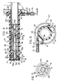
- the hand-grip 2 has a tubular plastics body with a hub 2a at one end and a collar 2b at the other end.
- the cylindrical cavity (indicated 2c) of the body of the hand-grip 2 houses the cylindrical end part 1a of the handlebar 1 with clearance.
- the body of the hand-grip 2 is mounted for rotation about its axis on the end 1a of the handlebar 1 by means of the hub 2a which slidingly engages a tubular metal rod 9 fixed inside the handlebar 1 and having an end part which projects from the end of the handlebar.
- the rod 9 is fixed in the handlebar 2 in the following manner.
- the end 9f of the rod inside the handlebar has a larger diameter than the rest of the rod 9 and has a threaded axial hole 9a into the end of which the cylindrical cavity 9b of the tubular rod 9 opens.
- a screw 10 with a conical head 10a and a hexagonal cavity 10b in its threaded end is screwed into the threaded hole 9a.
- the hexagonal cavity 10b enables the screw 10 to be operated by means of a key 11 of hexagonal cross-section ( Figure 3) which can be inserted through the cavity 9b in the rod 9.
- An expansible bush 12 for example of plastics material, is interposed between the conical head 10a of the screw 10 and the end surface 9c of the larger end portion of the rod 9, which is also conical, and has conical end surfaces complementary to the surface of the head 10a and the surface 9c.
- the screw 10 is tightened in the threaded hole 9a, the head 10a is brought towards the surface 9c and the bush 12 consequently expands in the cavity in the handlebar 1.
- the assembly constituted by the screw 10, the bush 12 and the rod 9 is thus firmly fixed to the handlebar 1.
- the expansible bush 12 is made from a bush of plastics material by the formation of longitudinal cuts in the wall of the bush, extending from alternate ends of the bush for a distance less than the overall length of the bush. These cuts can be seen, indicated 13, in Figure 7.
- the free end 9d of the tubular rod 9 projects through the hub 2a into a chamber 14 which is defined by the hub 2a, by a tubular extension 15 of the hand-grip body 2 extending beyond the hub 2a, and by a plug 16 of plastics material screwed into the tubular appendage 15.
- the indexing device for snap-locating the hand-grip in the various positions corresponding to the various gear ratios is mounted in the chamber 14.
- this device is substantially of the type illustrated in Figures 12 and 13 of the same Applicant's Italian Patent Application No. 21647-A/86 relating to lever-operated gears.
- This type of indexing device is fitted in the gear lever marketed by the Applicant under the trade mark "Syncro".
- the indexing device 17 includes two pin springs 18 each having an attachment end 18a fixed in a hole 19 ( Figures 7 and 5) formed in the wall of the hand-grip 2 and an active end 18b which engages the toothed surface of a toothed ring 20 fixed to the rod 9.
- the ring 20 is fitted over a bush 21 with two diametrally-opposed radial projections 22 which are housed in two seats 23 (one of which is partially visible in Figure 7) in the ring 20. The ring 20 is thus connected for rotation with the bush 21.
- the toothed ring 20 is fixed rigidly to the rod 9 and hence to the handlebar 1, whilst the two pin springs 18 can move with the hand-grip 2.
- the active ends 18b of the pin springs 18 are urged by the resilient loading of the springs against the toothed surface of the ring 20 so that the active ends snap-engage in successive spaces between the teeth of the ring 20 when the hand-grip 2 is rotated.
- the plug 16 has a central hole 16a which enables the key 11 to be inserted in order to lock the bush 12 in the handlebar 1 and release it therefrom, as described above.
- the use of the indexing device described above provides, amongst other things, a characteristic advantage of the device which has already been described in the Applicant's previous Italian Patent Application No. 21647-A/86.
- the toothed ring 20 can simply be replaced by a ring with a configuration such as to ensure the correct location of the chain in the various positions of engagement on the sprockets of the new set.
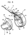
- the end collar 2b of the hand-grip 2 is housed in the skirt 26 of a clamp body 27 which is mounted around the handlebar 1 and is clamped thereto by the tightening of a tangential screw 28 which is used to close the clamp body (Figure 7).
- the clamp body 27 has a threaded hole 29 into which is screwed the threaded shank 30 of a screw 31 to which the end part of the sheath 4 ( Figures 4, 6, 8) of the flexible cable transmission 3 is fixed.
- a helical spring 32 is interposed between the screw 31 and the clamp body 27.
- the flexible metal cable, indicated 33, of the flexible cable transmission 3 passes through the sheath 4, the screw 31, the shank 30, and the hole 29 in the clamp body 27 and is housed in a circumferential groove 34 formed in the collar 2b.
- the end of the metal cable 33 is fixed to a bob 35 which is locked in a seat 36 defined by two recesses 37 formed in the facing radial walls of the collar 2b defining the groove 34.
- One of the recesses 37 is visible in Figure 8.
- the collar 2b also has a circumferential track 38 whose angular extent corresponds to the maximum possible travel of the hand-grip and which is defined at its ends by two walls 39 located in planes containing the axis of the hand-grip 2.
- the clamp body 27 has a radial hole 40 ( Figure 7) into which is screwed a pin 41 which projects inwardly of the clamp body and engages the track 38.
- a pin 41 which projects inwardly of the clamp body and engages the track 38.
- the collar 2b may have numbers on its peripheral surface indicative of the various gear ratios which can be engaged, whilst the skirt 26 of the clamp body 27 may have a window 5 (as in the embodiment shown in Figures 1 and 2) for displaying the gear ratio engaged.
- the hand-grip When the cyclist acts on the hand-grip 2 and rotates it about its axis, the hand-grip operates the rear derailleur of the bicycle by means of the metal cable 33.
- the indexing device 17 enables the hand-grip to be snap-located in the various positions corresponding to the engagement of the various gear ratios.
- the derailleur has a spring which tends to bias the derailleur (and hence the hand-grip 2 by means of the cable 33) towards the position corresponding to the engagement of the chain with the smallest-diameter sprocket (the highest gear ratio).
- the biassing force exerted by the derailleur spring is greatest.
- the device according to the invention may provide a helical spring 50 associated with the hand-grip 2. More precisely, the spring 50 is mounted coaxially around the tubular rod 9 and has respective tails 50a, 50b fixed to the larger end portion of of the rod 9 and to the hub 2a of the hand-grip 2. The tail 50a is thus fixed relative to the handlebar 1, whilst the tail 50b is movable with the hand-grip 2. The spring 50 is arranged so as to bias the hand-grip 2 in the opposite sense from the sense of biassing due to the derailleur spring.
- the spring 50 tends to bias the hand-grip 2 in the sense indicated by the arrow A in Figure 1, that is, in the sense corresponding to the engagement of the chain on larger-diameter sprockets.
- the derailleur spring biasses the hand-grip 2 in the sense indicated by the arrow B in Figure 2, which corresponds - as already stated - to the engagement of the chain on the smaller-diameter sprockets.
- the effects of the two springs reach an equilibrium condition when the chain is engaged on a sprocket intermediate the smallest-diameter sprocket and the largest -diameter sprocket.
- the spring 50 is mounted in such a way that, even when the chain is on the largest-diameter sprocket, it exerts a biassing force on the derailleur which opposes that exerted by the derailleur spring.
- the biassing effect on the chain which results from the opposite effects of the two springs is less, in absolute terms, than that which occurs in conventional controls which are subject only to the biassing of the spring associated with the derailleur itself. The risk of the undesired operation of the gears is therefore greatly reduced.
- the conformation of the toothed surface of the ring 20 is selected in dependence on the sprockets which have to mesh with the chain.
- the profiles of the teeth of the ring 20 can be selected - at the design stage - so as to achieve the desired amount of effort to be applied to the hand-grip in order to operate the gears.
- the profile of each tooth of the ring 20 may be asymmetrical, that is, with one flank steeper than the other, in order to oppose the displacement of the chain under the biassing effects of the two springs of the derailleur and the hand-grip in a different manner according to whether the chain is on the large sprockets or on the small sprockets. This may be necessary if the resultant effect of the two springs has a different absolute value according to whether the chain is on the large sprockets or on the small sprockets.
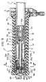
- the hand-grip 2 is covered by an outer rubber sheath G and has a tubular body of plastics material in one end of which a support bush 52 is inserted in abutment with internal radial appendages 53 in the cylindrical cavity 2c of the hand-grip 2.
- the bush 52 On each of its end faces, the bush 52 has three equiangularly-spaced notches 52a for keying the bush to the body of the hand-grip 2 in correspondence with the internal radial appendages 53 which are engaged in the notches.
- the body of the hand-grip 2 is mounted for rotation about its axis on the end 1a of the handlebar 1 by means of the support bush 52 whose central hole is engaged rotatably by the tubular rod 9.
- the rod 9 is fixed within the handlebar 1 by a pair of rings 54 divided each into three portions held together by spring clips 55 and separated by a central ring 56 with conical end surfaces complementary to the lateral surfaces of the rings 54, the rings being interposed between the conical head 10a of the screw 10 and the end surface 9c of the larger end portion 9f of the rod 9.
- the rings 54 also have conical end surfaces complementary to the surface of the head 10a of the locking screw 10 and the end surface 9c of the rod 9.
- the free end of the tubular rod 9 projects from the support bush 52 into a chamber defined by the bush 52, the body of the hand-grip 2 and a plug 16b of plastics material having axial holes 57 for the passage of tie bolts 58 whose threaded ends 58a are adapted to cooperate with threaded holes 52b in the support bush 52.
- the tightening of the tie bolts 58 locks the plug 16b on the end of the body of the hand-grip 2 by virtue of the axial engagement between the support bush 52 and the internal radial appendages 53 of the body of the hand-grip 2.
- the plug 16b On its lateral surface, the plug 16b also has three axial ribs 72 whose shapes correspond to those of three internal axial grooves 73 in the end of the tubular body of the hand-grip 2. The plug 16b is keyed to the hand-grip 2 by the engagement of the ribs 72 in the grooves 73.
- the indexing device 17 is mounted in the chamber delimited by the bush 52 and, in this embodiment, includes three pin springs 18, the attachment end 18a of each of which is secured in a hole 19a in the corresponding projection 53 formed on the inner wall of the hand-grip 2, its active end engaging the lateral toothed surface 20b of a toothed ring 20a keyed by its internal hole 60 on the free end of the tubular rod 9, which has two diametrally-opposed flat faces 9e.
- the toothed ring 20a thus faces the support bush 52 with the interposition of a shaped washer 25a which has outer radial tabs 25b and inner radial projections 25c whose functions will become clear from the following description.
- the toothed ring 20a also has an end face 20c with axial teeth oriented radially and corresponding to the teeth of the lateral surface 20b.
- a locking ring 62 which has axial projections 62a oriented radially towards the surface 20c, as well as radial appendages 62b whose shapes correspond to those of guides 63 in the plug 16b, is urged axially against the end surface 20c of the toothed ring 20a in a resilient manner by Belleville washers 61.
- the plug 16b has a central threaded hole 16c into which is screwed a screw-adjustment element 64 which includes a manually-operable end 64a and from the centre of which a rod 64b extends.
- the rod 64b has a threaded portion 65 connected to a circular cylindrical end portion 66 whose outside diameter corresponds to the diameters of the central holes in the Belleville washers 61.
- An annular shoulder 67 is thus defined between the threaded portion 65 and the cylindrical portion 66 of the rod 64b for cooperating with the first of the set of Belleville washers 61.
- the screw-adjustment element 64 also has a central through-hole 68 and, at its manually-operable end 64a, a toothed end surface 69 which is adapted to define, with a corresponding spring 70 carried by the plug 16b, auxiliary position-indexing means for the screw-adjustment element 64.
- the active ends 18b of the pin springs 18 are urged against the lateral toothed surface 20b of the toothed ring 20a by the resilient loading of the springs
- the axial projections 62a of the locking ring 62 are urged against the toothed end surface 20c of the ring 20a by the resilient loading of the Belleville washers 61, between the locking ring 62 and the annual shoulder 67 of the screw-adjustment element 64 so that both the active ends 18b of the pin springs 18 and the axial projections 62a of the locking ring 62 snap-engage the spaces between the teeth of the ring 20a successively when the hand-grip 2 is rotated.
- the locking ring 62 slides axially in the plug 16b and is guided in this movement by the radial appendages 62b which slide in the guides 63 of the plug.
- the hole 68 in the screw-adjustment element 64 allows the key 11 to be inserted in order to clamp and release the split rings 54 inside the handlebar 1, as described above.
- the user wishes to increase or decrease the average torque necessary to cause the hand-grip to snap from one position to another, he acts on the operating end 64a of the screw-adjustment element 64 which projects from both the plug 16b of the body of the hand-grip 2 and its outer rubber sheath G, its rotation being indexed by the spring 70 and the toothed end surface 69.
- the rotation of the element 64 varies the load exerted on the locking ring 62 by the Belleville washers 61 coaxial with the rod portion 64b so that the force required to operate the hand-grip can be varied in dependence on the kind of terrain over which the bicycle is travelling.
- the tie-bolts 58 cooperate with the outer radial appendages 25b of the washer 25a whose rotation is limited by the engagement between the inner radial appendages 25c and the diametrally opposed flat surfaces 9e at the free end of the tubular rod 9.
- the radial appendages 25b abut the tie-bolts 58 and the internal radial appendages 25c come into contact with one of the flat surfaces 9e to stop the rotation of the hand-grip 2.
Claims (20)
- Drehgriffvorrichtung zum Betätigen der Gänge eines Fahrrads, die einen Handgriff (2) enthält, der drehbar an einem Fahrradlenker (1) angebracht ist und über einen flexiblen Drahtzug (3) mit einer Fahrradgangschaltung verbunden ist, die den wahlweisen Eingriff einer Fahrradkette mit einem Satz verschiedener Ritzel steuert, die nebeneinander angeordnet sind, wobei die Gangschaltung mit einer ersten federnden Einrichtung versehen ist, die die Gangschaltung in eine Endstellung drückt, die dem Eingriff der Kette mit einem ersten Endritzel des Satzes entspricht, wobei die Vorrichtung des weiteren eine mit dem Handgriff (2) verbundene Rasteinrichtung (17) enthält, mit der der Handgriff in den verschiedenen Stellungen zum Einrasten gebracht wird, die dem Eingriff der Kette mit den verschiedenen Ritzeln entsprechen, wobei die Vorrichtung dadurch gekennzeichnet ist, daß eine zweite federnde Einrichtung (50) mit dem Handgriff verbunden ist und den Handgriff in die der Druckrichtung der ersten federnden Einrichtung der Fahrradgangschaltung entgegengesetzte Richtung drückt, so daß die aus der ersten und der zweiten federnden Einrichtung resultierende Wirkung die Kette in eine Stellung zwischen den beiden Endritzeln des Satzes drückt.
- Vorrichtung nach Anspruch 1, dadurch gekennzeichnet, daß die Rasteinrichtung einen Zahnring (20) enthält, der lösbar an dem Lenker angebracht ist und mit einem federnden Eingriffelement (18) zusammenwirkt, das von dem Handgriff (20) getragen wird und durch die Drehung des Handgriffs (2) in bezug auf den Lenker (1) in die Zwischenräume zwischen den Zähnen des Zahnrings (20) einschnappt.
- Vorrichtung nach Anspruch 2, dadurch gekennzeichnet, daß die Rasteinrichtung (17) zwei federnde Eingriffelemente (18) in Form von zwei Stiftfedern enthält, die jeweils ein an der Wand des Handgriffs (2) befestigtes hinteres Ende (18a) sowie ein mit dem Zahnring (20) zusammenwirkendes Ende (18b) haben.
- Vorrichtung nach Anspruch 2, dadurch gekennzeichnet, daß eine Stange (9) in dem Lenker angebracht ist und einen Endabschnitt (9d) enthält, der aus dem Lenker vorsteht und mit dem der Zahnring (20) verbunden ist, und an dem der Körper des Handgriffs (2) drehbar ist.
- Vorrichtung nach Anspruch 4, dadurch gekennzeichnet, daß der Körper des Handgriffs (2) eine röhrenartige Form hat und den Endabschnitt des Lenkers (1) aufnimmt sowie eine Nabe (2a) enthält, die drehbar am Endteil der Stange (9) angebracht ist, wobei der Körper des Handgriffs (2) des weiteren einen röhrenförmigen Ansatz enthält, der sich über die Nabe (2a) an der dem Lenker gegenüberliegenden Seite (1) erstreckt und eine Kammer (14) bildet, in der sich die Rasteinrichtung (17) befindet, wobei die Kammer durch eine Verschlußkappe (16) verschlossen ist, die in den röhrenförmigen Ansatz (15) eingeschraubt ist.
- Vorrichtung nach Anspruch 5, dadurch gekennzeichnet, daµ das Ende (9c) der röhrenförmigen Stange (9) in dem Lenker (1) ein mit Gewinde versehenes Loch (9a) aufweist, wobei eine Schraube (10) in das Loch (9a) eingeschraubt ist und sich eine dehnbare Buchse (12) zwischen dem inneren Ende (9c) der Stange (9) und dem Kopf (10a) der Schraube (10) befindet, so daß sie sich durch das Anziehen der Schraube (10) in dem mit Gewinde versehenen Loch (9a) gegen die Innenwand des Lenkers (1) ausdehnt.
- Vorrichtung nach Anspruch 2, dadurch gekennzeichnet, daß die zweite federnde Einrichtung durch eine Spiralfeder (50) gebildet wird, die koaxial um die Stange (9) herum angebracht ist, wobei entsprechende Enden (50a, 50b) am Körper der Stange (9) und am Körper des Handgriffs (2) befestigt sind.
- Vorrichtung nach Anspruch 1, dadurch gekennzeichnet, daß das innere Ende (2b) des Körpers des Handgriffs (2) einen Ring aufweist, der sich in einem Rand (26) eines Klemmkörpers (27) befindet, der um den Lenker (1) herum geklemmt wird, wobei der Ring (2b) eine Umfangsbahn (38) aufweist, deren Winkelausdehnung der maximalen Winkelbewegung des Handgriffs entspricht, und die einen Radialstift (41) aufnimmt, der von dem Klemmkörper (27) gehalten wird und radial nach innen von dem Körper vorsteht, so daß der Kontakt des Stiftes (41) mit den Endflächen der Umfangsbahn (38) die Endstellungen der Winkelbewegung des Handgriffs (2) bestimmt.
- Vorrichtung nach Anspruch 8, dadurch gekennzeichnet, daß der Klemmkörper (27) ein Loch (29) zur Befestigung der Abschlußschraube (31) der Ummantelung (4) des flexiblen Drahtzuges aufweist, wobei der Ring (2b) eine Umfangsnut (34) aufweist, die den flexiblen Metalldraht des flexiblen Drahtzuges (3) aufnimmt, sowie eine Aufnahme (36) für einen vergrößerten Endabschnitt (35) des flexiblen Drahtes (33).
- Vorrichtung nach Anspruch 1, dadurch gekennzeichnet, daß sie eine Einstelleinrichtung (64, 16b, 61, 62, 62b, 20c) enthält, die mit der Rasteinrichtung (18, 20b) verbunden ist und mit der das für das Einschnappdrehen des Handgriffs (2) zwischen zwei aufeinanderfolgenden Stellungen erforderliche Drehmoment verändert wird.
- Vorrichtung nach Anspruch 10, dadurch gekennzeichnet, daß die Einstelleinrichtung ein Schraubeinstellelement (64) enthält, das sich in einer entsprechenden, mit Gewinde versehenen Aufnahme (16c) in dem Handgriff (16b, 2) befindet und den Federdruck eines entsprechenden, von dem Handgriff (2) getragenen Eingriffelementes (62) ändert, das in Zwischenräumen zwischen Zähnen (20c) eines lösbar an dem Handgriff (1) angebrachten Zahnrings (20a) einrastet.
- Vorrichtung nach Anspruch 11, dadurch gekennzeichnet, daß der Zahnring (20a) eine mit Zähnen versehene Seitenfläche (20b) hat, die mit federnden Eingriffelementen (18) zusammenwirkt, die sich zwischen einer Innenwand des Handgriffs (2) und dem Zahnring (20a) und einer Endfläche (20c) befinden, die ebenfalls mit Zähnen versehen ist und mit entsprechenden Endvorsprüngen (62a) eines auf den Handgriff (63, 16b, 2) aufgekeilten Sperrings (62) zusammenwirkt, wobei sich federnde Einrichtungen (61) zwischen dem Sperring (62) und dem Schraubeinstellelement (64) befinden, die den Sperring (62) an die Endfläche (20c) des Zahnrings (20a) drücken.
- Vorrichtung nach Anspruch 12, dadurch gekennzeichnet, daß das Schraubenelement (64a) einen manuell zu betätigenden Ansatz (64a) mit einem mit Zähnen versehenen Abschnitt (69) enthält, der mit einem zusätzlichen federnden Eingriffelement (70), das von dem Handgriff (16b, 2) getragen wird, eine zusätzliche Stellungsrasteinrichtung für das Schraubenelement (64) bildet.
- Vorrichtung nach Anspruch 12 oder Anspruch 13, dadurch gekennzeichnet, daß die zwischen dem Sperring (62) und dem Schraubeinstellelement (64) befindlichen federnden Einrichtungen eine Vielzahl von mit dem Schraubenelement (64) koaxialen Tellerfedern (61) umfassen.
- Vorrichtung nach einem der Ansprüche 10 bis 14, dadurch gekennzeichnet, daß eine Stange (9) in dem Lenker (1) befestigt ist und einen Endabschnitt (9d) enthält, der aus dem Lenker vorsteht, wobei der Zahnring (20a) mit dem Endabschnitt (9d) verbunden ist, und der Körper des Handgriffs (2) daran drehbar ist.
- Vorrichtung nach Anspruch 15, dadurch gekennzeichnet, daß zwischen dem Körper des Handgriffs (2), der röhrenförmig ist, um den Endabschnitt (1a) des Lenkers (1) aufzunehmen, und der Stange (9) eine Lagerbuchse (52) angebracht ist, die am Handgriff (2) befestigt und am Endabschnitt (9d) der Stange (9) drehbar ist, wobei ein Ende (2a) des Handgriffs, das sich über die Lagerbuchse (52) erstreckt, eine Verschlußkappe (16b) aufweist, die auf den Handgriff (2) aufgekeilt ist.
- Vorrichtung nach Anspruch 16, dadurch gekennzeichnet, daß die Innenwand des Handgriffs (2) radiale Vorsprünge (53) aufweist, die die federnden Eingriffelemente (18) halten, und die an der Lagerbuchse (52) anliegen, wobei Zugbolzen (58) zwischen der Buchse (52) und der Verschlußkappe (16b) angebracht sind, um die Lagerbuchse (52) und die Verschlußkappe (16b) an dem Handgriff (2) zu befestigen.
- Vorrichtung nach Anspruch 17, dadurch gekennzeichnet, daß sich die mit Gewinde versehene Aufnahme (16c) für das Schraubenelement (64) in der Mitte der Verschlußkappe (16b) befindet.
- Vorrichtung nach einem der Ansprüche 16 bis 18, dadurch gekennzeichnet, daß das Ende (9c) der röhrenförmigen Stange (9) in dem Lenker (1) ein mit Gewinde versehenes Loch (9a) aufweist, in das eine Schraube (10) eingeschraubt wird, wobei sich dehnbare Ringe (54) zwischen dem inneren Ende (9c) der Stange (9) und dem Kopf der Schraube (10) befinden, so daß sie sich durch das Anziehen der Schraube (10) in dem mit Gewinde versehenen Loch (9a) gegen die Innenwand des Lenkers (1) ausdehnen, wobei das Schraubeinstellelement (64) eine mittlere Durchgangsbohrung (68) zur Durchführung eines Anziehwerkzeugs (11) aufweist.
- Fahrradlenker, der an seinen Enden zwei Betätigungsvorrichtungen nach einem der vorangehenden Ansprüche zur Betätigung der vorderen Gangschaltung bzw. der hinteren Gangschaltung des Fahrrads enthält.
Applications Claiming Priority (4)
| Application Number | Priority Date | Filing Date | Title |
|---|---|---|---|
| IT6790589 | 1989-10-20 | ||
| IT06790589A IT1238133B (it) | 1989-10-20 | 1989-10-20 | Dispositivo di comando a manopola girevole per un cambio di bicicletta |
| IT6740390 | 1990-06-04 | ||
| IT67403A IT1241239B (it) | 1990-06-04 | 1990-06-04 | Dispositivo di comando indicizzato a manopola girevole per un cambio di bicicletta. |
Publications (2)
| Publication Number | Publication Date |
|---|---|
| EP0423779A1 EP0423779A1 (de) | 1991-04-24 |
| EP0423779B1 true EP0423779B1 (de) | 1994-04-20 |
Family
ID=26329767
Family Applications (1)
| Application Number | Title | Priority Date | Filing Date |
|---|---|---|---|
| EP90119957A Expired - Lifetime EP0423779B1 (de) | 1989-10-20 | 1990-10-18 | Drehgriffvorrichtung zum Betätigen der Gangschaltungen eines Fahrrads |
Country Status (4)
| Country | Link |
|---|---|
| US (1) | US5134897A (de) |
| EP (1) | EP0423779B1 (de) |
| JP (1) | JP2951391B2 (de) |
| DE (1) | DE69008298T2 (de) |
Families Citing this family (62)
| Publication number | Priority date | Publication date | Assignee | Title |
|---|---|---|---|---|
| JPH04260889A (ja) * | 1991-02-13 | 1992-09-16 | Maeda Kogyo Kk | 自転車用変速操作装置 |
| US5102372A (en) * | 1991-03-20 | 1992-04-07 | Sram Corporation | Bicycle derailleur cable actuating system |
| JPH04342684A (ja) * | 1991-05-17 | 1992-11-30 | Maeda Kogyo Kk | 自転車用ディレーラ |
| JPH0820378A (ja) * | 1991-11-11 | 1996-01-23 | Mori San Tour:Kk | 自転車用変速機構およびこれを用いた変速方法 |
| JP3359663B2 (ja) * | 1992-09-21 | 2002-12-24 | 株式会社シマノ | 自転車用の変速操作装置付きブレーキレバー装置 |
| US5241877A (en) * | 1992-12-04 | 1993-09-07 | Chen Chun Hsung | Gear selector |
| JPH06199270A (ja) * | 1992-12-28 | 1994-07-19 | Mori San Tsuaa:Kk | 自転車用変速操作装置 |
| JPH06239287A (ja) * | 1993-02-12 | 1994-08-30 | Mori San Tsuaa:Kk | 自転車用変速操作装置 |
| EP0683092A1 (de) * | 1993-04-01 | 1995-11-22 | Guy V.O. Bulkeley | Verbinder für Motorradbetätigungshebel |
| JP3644602B2 (ja) * | 1994-02-23 | 2005-05-11 | 株式会社シマノ | 自転車用変速操作装置 |
| US6199447B1 (en) | 1994-03-07 | 2001-03-13 | Sram Corporation | Bulbous grip for rotatable bicycle gear shifter |
| JPH0844450A (ja) * | 1994-03-07 | 1996-02-16 | Sram Corp | 回動型グリップ作動装置及びその回り止め機構 |
| US5564316A (en) * | 1994-03-07 | 1996-10-15 | Sram Corporation | Nubbed grip for rotatable bicycle gear shifter |
| US5476019A (en) * | 1994-03-07 | 1995-12-19 | Sram Corporation | Rotatable handgrip actuating system |
| DE4420273A1 (de) * | 1994-06-10 | 1995-12-14 | Helmig Hans Gmbh | Drehgriff zur Betätigung von Fahrradgangschaltungen |
| US5666859A (en) * | 1994-12-02 | 1997-09-16 | Fichtel & Sachs Ag | Latching shifter for a bicycle transmission |
| US5799541A (en) * | 1994-12-02 | 1998-09-01 | Fichtel & Sachs Ag | Twist-grip shifter for bicycles and a bicycle having a twist-grip shifter |
| US5823058A (en) * | 1994-12-02 | 1998-10-20 | Mannesmann Sachs Ag | Twist-grip shifter for bicycles and a bicycle having a twist-grip shifter |
| EP0718185B1 (de) * | 1994-12-20 | 2000-03-22 | Shimano Inc. | Steuerungseinrichtung für eine Fahrradgangschaltung mit einer Federeinrichtung |
| US5620383A (en) * | 1995-02-06 | 1997-04-15 | Sram Corporation | Bicycle derailleur and actuating system |
| DE69623086T2 (de) * | 1995-03-13 | 2003-05-08 | Sakae Co Ltd | Steuerungseinrichtung für eine fahrradgangschaltung |
| US5797296A (en) * | 1995-03-31 | 1998-08-25 | Sugino Cycle Industries, Ltd. | Bicycle speed change operation assembly |
| CA2253892A1 (fr) | 1995-08-03 | 1997-02-20 | Franck Savard | Dispositif de compensation d'effort pour une commande a cable d'un derailleur, notamment pour un velo |
| FR2737463B1 (fr) * | 1995-08-03 | 1999-04-30 | Franck Savard | Dispositif de compensation d'effort pour une commande a cable d'un derailleur, notamment pour un velo |
| US6055882A (en) * | 1995-09-20 | 2000-05-02 | Fichtel & Sachs Ag | Twist-grip shifter for bicycles |
| IT1290791B1 (it) * | 1995-10-31 | 1998-12-10 | Campagnolo Srl | Dispositivo di comando di un deragliatore di bicicletta, con organo di comando montato girevole sul manubrio della bicicletta. |
| US5678455A (en) * | 1996-02-15 | 1997-10-21 | Shimano, Inc. | Bar-end shifting device |
| JP3678496B2 (ja) * | 1996-05-30 | 2005-08-03 | 株式会社シマノ | 自転車用変速操作装置 |
| US5682963A (en) * | 1996-07-12 | 1997-11-04 | Tang; Jen-Hui | Brake assembly for a bicycle |
| DE19651577C2 (de) * | 1996-12-12 | 1999-02-18 | Sram De Gmbh | Drehgriffschalter für Fahrradgetriebe |
| AT406365B (de) * | 1997-02-21 | 2000-04-25 | Josef Prajczer | Fahrradgangschaltung |
| US5784924A (en) * | 1997-03-25 | 1998-07-28 | Wu; Mu-Chuan | Gearshift adjusting device |
| US5860326A (en) * | 1997-03-26 | 1999-01-19 | Corporacion Resentel S.A. De C.V. | Combined speed shifter and brake handle assembly |
| US6484603B2 (en) * | 1997-12-05 | 2002-11-26 | Sram Deutschland Gmbh | Selector for a bicycle gear mechanism |
| DE19922327A1 (de) | 1999-05-14 | 2000-11-16 | Sram De Gmbh | Verschlußglied für eine Montageöffnung an einem Schalter für Fahrräder |
| US6293882B1 (en) | 1999-12-10 | 2001-09-25 | Shimano, Inc. | Operating force compensating apparatus for a bicycle transmission |
| US6328138B1 (en) | 1999-12-10 | 2001-12-11 | Shimano Inc. | Brake operating device with modulator |
| US6244415B1 (en) | 1999-12-30 | 2001-06-12 | Shimano, Inc. | Motor controlled shift control device including an idler gear for a bicycle transmission |
| DE10013262A1 (de) * | 2000-03-17 | 2001-09-20 | Sram De Gmbh | Einwegkraftübertragung |
| DE10025883A1 (de) * | 2000-05-25 | 2001-11-29 | Sram De Gmbh | Integrierter Drehgriffschalter |
| KR20010110061A (ko) * | 2000-05-30 | 2001-12-12 | 마재열 | 자전거의 변속 레버장치 |
| ITTO20010010A1 (it) * | 2001-01-11 | 2002-07-11 | Campagnolo Srl | Gruppo integrato di comando del cambio e del freno per una bicicletta. |
| US20030140725A1 (en) * | 2001-02-22 | 2003-07-31 | Liu Jen-Chih | Manual shift mechanism of a bicycle |
| US6571726B2 (en) * | 2001-04-27 | 2003-06-03 | Sunrace Roots Enterprise Co., Ltd. | Device for monitoring gear lever position |
| US6488130B1 (en) * | 2001-05-10 | 2002-12-03 | John Karl Bermel | Twist-grip brake for a cargo portage device |
| US6792825B2 (en) * | 2001-06-28 | 2004-09-21 | Shimano Inc. | Bicycle shift control device |
| DE10132000A1 (de) * | 2001-07-02 | 2003-01-16 | Sram De Gmbh | Gehäuse für Betätigungseinrichtung |
| US7117762B2 (en) | 2002-04-10 | 2006-10-10 | Sram Corporation | Bicycle gear indicator mechanism |
| DE10216168A1 (de) * | 2002-04-12 | 2003-10-23 | Sram De Gmbh | Drehgriffschalter mit kleinem Drehmoment |
| US7350436B2 (en) * | 2004-03-29 | 2008-04-01 | Shimano, Inc. | Electrical bicycle shift control device |
| US7793751B2 (en) * | 2005-04-01 | 2010-09-14 | Honda Motor Company, Ltd. | Vehicles including control assemblies having rotatable control knobs |
| DE102006060345A1 (de) * | 2006-12-20 | 2008-06-26 | Gustav Magenwirth Gmbh & Co. Kg | Griffrohr |
| JP5311556B2 (ja) * | 2008-12-25 | 2013-10-09 | 朝日電装株式会社 | スロットルグリップ装置 |
| JP5448148B2 (ja) * | 2009-06-05 | 2014-03-19 | 朝日電装株式会社 | スロットルグリップ装置 |
| US9651138B2 (en) | 2011-09-30 | 2017-05-16 | Mtd Products Inc. | Speed control assembly for a self-propelled walk-behind lawn mower |
| CN103707984A (zh) * | 2013-12-20 | 2014-04-09 | 柳州译海网络科技有限公司 | 一种电动车防掉落调速把手 |
| CN103879500A (zh) * | 2013-12-20 | 2014-06-25 | 柳州译海网络科技有限公司 | 一种带防掉落调速把手的电动车龙头 |
| IT201600111274A1 (it) * | 2016-11-04 | 2018-05-04 | Freni Brembo Spa | Dispositivo a leva |
| IT201600120097A1 (it) * | 2016-11-28 | 2018-05-28 | Giovanni Conte | Carrozzina motorizzata per disabili o anziani. |
| DE102018001253A1 (de) * | 2017-03-20 | 2018-09-20 | Sram Deutschland Gmbh | Hinteres Schaltwerk zur koaxialen Montage |
| US10668974B2 (en) * | 2018-01-02 | 2020-06-02 | Thomas Erdmann | Throttle tube with cable side radial bearing located inline with cable cam housing |
| US11052963B2 (en) | 2018-01-02 | 2021-07-06 | Thomas Erdmann | Throttle tube with radial bearing for ride by wire throttle systems |
Family Cites Families (9)
| Publication number | Priority date | Publication date | Assignee | Title |
|---|---|---|---|---|
| BE537784A (de) * | 1900-01-01 | |||
| DE864813C (de) * | 1951-06-16 | 1953-01-29 | Gustav Magenwirth Komm Ges | Drehschaltgriff fuer Kraftraeder |
| US3752006A (en) * | 1972-07-24 | 1973-08-14 | C Bartlett | Throttle assist mechanism for motorcycle |
| JPS5247238A (en) * | 1975-10-13 | 1977-04-14 | Shimano Industrial Co | External transmission |
| FR2510508A1 (fr) * | 1979-06-15 | 1983-02-04 | Saker | Dispositif de commande du regime des gaz d'un moteur a combustion interne |
| DE3012034A1 (de) * | 1980-03-28 | 1981-10-15 | Gustav Magenwirth Gmbh & Co, 7432 Urach | Gasdrehgriff fuer den lenker eines motorgetriebenen zweiradfahrzeuges |
| FR2575434B1 (fr) * | 1984-12-28 | 1989-05-19 | Huret & Fils | Dispositif de commande, notamment pour derailleur de cycle |
| DE3727505C2 (de) * | 1986-09-09 | 1996-10-10 | Campagnolo Spa | Gangwähler für eine Fahrrad-Gangschaltung |
| DE8708206U1 (de) * | 1987-06-11 | 1987-08-06 | Unseld, Hans-Peter, Dr., 7800 Freiburg, De |
-
1990
- 1990-10-18 US US07/600,375 patent/US5134897A/en not_active Expired - Lifetime
- 1990-10-18 EP EP90119957A patent/EP0423779B1/de not_active Expired - Lifetime
- 1990-10-18 DE DE69008298T patent/DE69008298T2/de not_active Expired - Fee Related
- 1990-10-19 JP JP2283241A patent/JP2951391B2/ja not_active Expired - Lifetime
Also Published As
| Publication number | Publication date |
|---|---|
| US5134897A (en) | 1992-08-04 |
| EP0423779A1 (de) | 1991-04-24 |
| DE69008298D1 (de) | 1994-05-26 |
| JPH03176290A (ja) | 1991-07-31 |
| DE69008298T2 (de) | 1994-08-04 |
| JP2951391B2 (ja) | 1999-09-20 |
Similar Documents
| Publication | Publication Date | Title |
|---|---|---|
| EP0423779B1 (de) | Drehgriffvorrichtung zum Betätigen der Gangschaltungen eines Fahrrads | |
| US5390565A (en) | Bicycle speed change system, bicycle speed change method and bicycle speed change operation assembly | |
| EP0916570B1 (de) | Einstellvorrichtung für Bowdenzug | |
| US5476019A (en) | Rotatable handgrip actuating system | |
| EP1043221B1 (de) | Freilauf für ein Fahrrad | |
| USRE39528E1 (en) | Bicycle hub with spacer and detachable freewheel | |
| US5241877A (en) | Gear selector | |
| US5836844A (en) | Rear derailleur for a bicycle | |
| US20130288834A1 (en) | Bicycle derailleur with rotation resistance and resistance control | |
| EP1040993A2 (de) | Drehbare Dichtungsanordnung für eine Fahrradantriebsnabe | |
| EP1213157A2 (de) | Fahrradnabe mit Gewindeabstandshalter und lösbarem Freilauf | |
| US5272936A (en) | Bicycle headset | |
| EP1288118B2 (de) | Bremssteuervorrichtung mit Modulator | |
| US6405613B1 (en) | Cable saver mechanism | |
| US10189306B2 (en) | Rear hub and bicyclic axle | |
| GB1592078A (en) | Multi-speed hub for a bicycle | |
| US4348916A (en) | Brake operating device for a bicycle | |
| EP1935770B1 (de) | Montagestruktur für Fahrradteile | |
| JPH09240567A (ja) | 自転車変速装置用制御装置 | |
| EP0422240B1 (de) | Fahrradbremse | |
| US20210061403A1 (en) | Grip system | |
| US4437357A (en) | Double lever assembly for bicycle speed control | |
| GB1592077A (en) | Multi-speed hub for a bicycle | |
| US6029780A (en) | Brakes for bicycles and other chain driven mechanisms | |
| US10946934B2 (en) | Actuation device for a control cable for a bicycle gearshift |
Legal Events
| Date | Code | Title | Description |
|---|---|---|---|
| PUAI | Public reference made under article 153(3) epc to a published international application that has entered the european phase |
Free format text: ORIGINAL CODE: 0009012 |
|
| AK | Designated contracting states |
Kind code of ref document: A1 Designated state(s): DE ES FR |
|
| 17P | Request for examination filed |
Effective date: 19911015 |
|
| 17Q | First examination report despatched |
Effective date: 19930713 |
|
| GRAA | (expected) grant |
Free format text: ORIGINAL CODE: 0009210 |
|
| AK | Designated contracting states |
Kind code of ref document: B1 Designated state(s): DE ES FR |
|
| PG25 | Lapsed in a contracting state [announced via postgrant information from national office to epo] |
Ref country code: ES Free format text: THE PATENT HAS BEEN ANNULLED BY A DECISION OF A NATIONAL AUTHORITY Effective date: 19940420 |
|
| REF | Corresponds to: |
Ref document number: 69008298 Country of ref document: DE Date of ref document: 19940526 |
|
| ET | Fr: translation filed | ||
| PLBE | No opposition filed within time limit |
Free format text: ORIGINAL CODE: 0009261 |
|
| STAA | Information on the status of an ep patent application or granted ep patent |
Free format text: STATUS: NO OPPOSITION FILED WITHIN TIME LIMIT |
|
| 26N | No opposition filed | ||
| PG25 | Lapsed in a contracting state [announced via postgrant information from national office to epo] |
Ref country code: FR Effective date: 19950630 |
|
| PG25 | Lapsed in a contracting state [announced via postgrant information from national office to epo] |
Ref country code: DE Effective date: 19950701 |
|
| REG | Reference to a national code |
Ref country code: FR Ref legal event code: ST |