EP0422915A2 - Structure modulaire pour garer des véhicules, éléments pour cela et méthode pour leur assemblage - Google Patents
Structure modulaire pour garer des véhicules, éléments pour cela et méthode pour leur assemblage Download PDFInfo
- Publication number
- EP0422915A2 EP0422915A2 EP90311099A EP90311099A EP0422915A2 EP 0422915 A2 EP0422915 A2 EP 0422915A2 EP 90311099 A EP90311099 A EP 90311099A EP 90311099 A EP90311099 A EP 90311099A EP 0422915 A2 EP0422915 A2 EP 0422915A2
- Authority
- EP
- European Patent Office
- Prior art keywords
- units
- unit
- structure according
- fabricated
- modular construction
- Prior art date
- Legal status (The legal status is an assumption and is not a legal conclusion. Google has not performed a legal analysis and makes no representation as to the accuracy of the status listed.)
- Withdrawn
Links
- 238000000034 method Methods 0.000 title claims abstract description 27
- 238000010276 construction Methods 0.000 claims abstract description 22
- 239000004567 concrete Substances 0.000 claims description 11
- 239000000203 mixture Substances 0.000 claims description 2
- 230000001419 dependent effect Effects 0.000 claims 2
- 239000011150 reinforced concrete Substances 0.000 description 17
- 239000000463 material Substances 0.000 description 14
- 239000013256 coordination polymer Substances 0.000 description 12
- 229910000831 Steel Inorganic materials 0.000 description 11
- 239000010959 steel Substances 0.000 description 11
- 239000002184 metal Substances 0.000 description 10
- 238000013459 approach Methods 0.000 description 5
- 230000000284 resting effect Effects 0.000 description 5
- 238000011161 development Methods 0.000 description 3
- 230000001154 acute effect Effects 0.000 description 2
- 230000001174 ascending effect Effects 0.000 description 2
- 239000004568 cement Substances 0.000 description 2
- 230000001010 compromised effect Effects 0.000 description 2
- 239000011440 grout Substances 0.000 description 2
- 241000237970 Conus <genus> Species 0.000 description 1
- 241001669573 Galeorhinus galeus Species 0.000 description 1
- 230000033228 biological regulation Effects 0.000 description 1
- 238000007796 conventional method Methods 0.000 description 1
- 230000007423 decrease Effects 0.000 description 1
- 230000003028 elevating effect Effects 0.000 description 1
- 238000003780 insertion Methods 0.000 description 1
- 230000037431 insertion Effects 0.000 description 1
- 238000012986 modification Methods 0.000 description 1
- 230000004048 modification Effects 0.000 description 1
- 230000002787 reinforcement Effects 0.000 description 1
- 230000002441 reversible effect Effects 0.000 description 1
- 238000005476 soldering Methods 0.000 description 1
- 239000002699 waste material Substances 0.000 description 1
- 238000003466 welding Methods 0.000 description 1
Images


Classifications
-
- E—FIXED CONSTRUCTIONS
- E04—BUILDING
- E04H—BUILDINGS OR LIKE STRUCTURES FOR PARTICULAR PURPOSES; SWIMMING OR SPLASH BATHS OR POOLS; MASTS; FENCING; TENTS OR CANOPIES, IN GENERAL
- E04H6/00—Buildings for parking cars, rolling-stock, aircraft, vessels or like vehicles, e.g. garages
- E04H6/08—Garages for many vehicles
- E04H6/10—Garages for many vehicles without mechanical means for shifting or lifting vehicles, e.g. with helically-arranged fixed ramps, with movable ramps
Definitions
- the present invention relates to a modular pre-fabricated structure for vehicle parking (e.g. for use as a parking lot) which can be quickly constructed and dissembled.
- the invention also relates to the individual pre-fabricated parts for such a structure and to a method for combining them.
- a multi-storey structure for vehicle parking characterised by: a plurality of first units each having the form of a horizontal platform member integral with a plurality of supporting legs, a plurality of second units each having the form of a generally planar deck member and interconnecting the platform members of at least two spaced apart first units and such as to be supported by said first units, and a plurality of ramp units to interconnect a said member at one level of the multi-storey structure with a said member at another level, the said units being all pre-fabricated and of modular construction dimensioned such as to interfit with one another.
- a pre-fabricated unit of modular construction for use as a said first unit or as a said second unit or as a ramp unit or as a staircase unit in a structure according to said one aspect of this invention.
- a method of erecting a multi-storey structure from a plurality of pre-fabricated units of modular construction provided with vertically-directed hollow passages therein said method being characterised by securing the units to a foundation by tensioning cables extending through said hollow passages.
- a method of re-erecting a multi-storey structure erected by a method according to the preceding paragraph characterised in that the tension in said cables is released, the units are disassembled, some or all of the units (with or without additional such units) are re-erected in a different configuration and/or at another location and secured (again) to a foundation by (the) tensioning cables extending through the hollow passages in the re-erected units.
- temporary use may be made of a vacant plot of land in the centre of town on which it is not worthwhile contructing a permanent parking lot because the owner of the plot is likely to decide at a future date to put the plot of land to a different use.
- the different units can be dissembled and be transported in their entirety to another plot of land to be set up again as a new multi-level parking system.
- the invention relates to a parking lot, the individual parts comprising it and the method for combining them.
- the parking lot is a modular pre-fabricated single or multi-level structure constructed of one or more different types of units which are combined according to the desired size and shape of the structure and which can be dismantled and rebuilt or permanently assembled according to the designated purpose of the structure and/or the land.
- the modular pre-fabricated parking lot is composed of parking units which will hereinafter be denoted as A, a path between the parking units which will be denoted as B, from elements involved in the approach to the parking lot (such as ramps and steps) which will hereinafter be denoted as C, and from an element of the foundation to be denoted as D.
- T The types of units which compose the parking spaces A will be denoted T, CP, and L, and they are as follows: a.
- Units which will hereinafter be denoted as Type T (Table) are table-like units made of reinforced concrete or any other appropriate rigid material. That is, their form is that of a square surface resting on four columns. Along each column there passes one hollow pipe which protrudes from the upper end of the column. Actually each such table-like unit is a combination of columns, beams, and a ceiling into one unit.
- T-type units can be constructed in various ways.
- T1 a unit to be hereinafter denoted T1
- T2 a unit to be hereinafter denoted T2 in which on both sides of the surface's width and on one of the sides of the length there is a recess.
- Type-T units may be constructed without any recess or with any other modification, such as with projections for support instead of recesses.
- two of the table's columns may be combined into a table with one two or three walls which pass between the columns.
- a parking lot comprised only of Type-T units which stand adjacent to one another can be constructed.
- the space between the "table's" legs is utilized for parking.
- one table unit is placed on another such that the bottom of each table leg on the upper level fits into the end of the pipe which protrudes from the column of the table on the lower level.
- a conic-shaped space at the bottom of each column allows for a good fit and insertion of the opening on the bottom of the table on the upper level into the pipes protruding from the level beneath it.
- Units to be hereinafter denoted CP are connecting plates of reinforced concrete or any other rigid material.
- These connecting plates may be constructed in various ways and may optionally contain one or more holes on the width, such that into these holes can be fitted the pipes protruding from the columns in unit T. These holes can be conically shaped, that is - wider at the bottom - so as to make the fit easier.
- the CP units may also optionally include recesses along the length or width which serve as lower beams or as a base. The CP units function as a bridge between the table units T in order to provide additional parking space and to aid in the horizontal linkage of the structure.
- two CP units may be placed between two pairs of tables to Type T1 and T2 (adjacent to one another) along their length, with each CP leaning on a recess on the width of the table. similarly, more CP units can be placed between a greater number of tables, with the connecting plates leaning on the length or width of the table on recesses or on projections.
- the preferred method of constructing the parking spaces is by placing three tablets to be denoted CP1, CP2 and CP3 between two pairs of tables - T1 and T2. It should be emphasized that each pair of tables is adjacent to each other along the length. These three connecting plates are located on one side on the widthwise recess of the T1 T2 pair and on the other - on the widthwise recess of another adjacent T1 T2 pair. The pipes protruding from the columns of the T1 T2 tables pass through holes in the appropriate places on the width of the connecting plates.
- the central connecting plate - CP2 - leans partially on table T1 and partially on Table T2 and thus in the center of its width are two holes through which the end of the pipe from table T1 and the end of the pipe of table T2 pass.
- the connecting plats serves also for the horizontal linkage of the structure's tables.
- the horizontal linkage between the type T units can be made by a metal plate with holes which are fitted into the pipes protruding from the columns of adjacent tables, or alternatively - by means of said connecting plates.
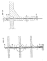
- the vertical connection between the tables which allows for the creation of a structure with several levels is made by passing a steel cable along the length of the hollow pipes and tying and suspending it on the top of the upper unit and on the bottom edge which is located in the foundations.
- a permanent vertical connection may be made by pouring any cement-base material which hardens, such as grout, into the hollow pipes which pass along the length of the table's columns.
- Units to be denoted below as types L units are optional in the parking lot, and with their aid, additional parking spaces may be added at the edges of the structure.
- These units which are also made of reinforced concrete, are composed of a plate which stands on two columns on one of its sides and which has the shape of a table which is missing two legs on one of its widths. This item is placed in the structure so that on one side it stands on the two columns, and on the other - the plate leans on the width side of table T such that the holes on the edge of the plate fit into the ends of the pipes which protrude from the table's columns.
- the three units to be denoted below L1, L2 and L3 are attached on the structure's edge to the pair of units T1 T2, such that the connection of the plates of the elements L1, L2, and L3 to the pair of tables is done in exactly the same way as the connection of the CP1, CP2, and CP3 units to the tables.
- R and S. a The units which create an approach to the parking lot will be hereinafter denoted as R and S. a.
- the units to be denoted hereinafter as R are ramps for vehicles to ascend to higher levels in the parking lot.
- the ramps are constructed of four subunits to be hereinafter denoted as R1, R2, R3 and R4. All are made of reinforced concrete or other rigid materials.
- R1 is a sloped unit on which a vehicle ascends part of the way to a higher level.
- a beam which supports the ramp and which also serves as a railing to prevent vehicles from falling.
- One side of the unit leans on the ground or on the bottom of the lower unit, and the other - on two columns.
- R2 is a sloped unit shaped like a table whose legs on one side are shorter than on the other and on which the vehicle ascends to a higher level.
- a beam which supports the ramp and which serves also as a railing to prevent vehicles from falling.
- R3 is a unit similar to R2, which allows the vehicle's continued ascent to the top level. It is table-shaped, and optionally along its length on the external side there is a beam supporting the ramp and also preventing vehicles from falling.
- R4 is a unit which is also table-like in shape and which serves as an area for entry of vehicles to the parking lots.
- the ramp may be constructed consecutively or alternatively - non-consecutively, such that the ramp reaches a given level and the vehicle ascends to another ramp which stands on the ramp below it.
- the construction of the ramp can be similar to the construction of the parking spaces, except that the R2 unit is a sloped table and R4 is a horizontal table, and R1 and R3 are connecting plates with holes fitting into R2 and R4 units respectively.
- Units to be hereinafter denoted S are steps made of reinforced concrete or any other rigid material and which connect the various levels for pedestrians.
- steel railings may be added to prevent falls from the parking level and for decorative purposes.
- the railings may be added to the T and CP units.
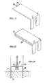
- Unit D is a foundation unit made of metal, its shape being a hollow cylinder or a cube and on its top end there protrudes a hollow pipe on which the table column rests.
- This foundation unit is mostly sunken into the concrete poured into the structure's foundations, and its upper part protrudes above the cement.
- the table's legs stand on such units so that the pipe which protrudes from the upper end of the foundation unit enters the conic opening on the bottom of the table's legs.
- To this unit is attached the suspended cable so as to attach to the foundations.
- the present invention relates to the parking lot itself, the units which compose it and the method for its construction.
- the invention in its entirety, including the method for its construction, will be clarified and exemplified with the aid of Figures 1 through 30. These examples and figures are in no way intended to limit the scope of the protection of the present invention.
- units the modular pre-fabricated units of the system
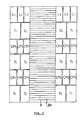
- the above figure presents an example of a parking lot with a ramp (1) by means of which the vehicles move from level to level, but according to the present invention parking lots may be constructed with elevators which will take the vehicles up and down between the levels. (For the details of the ramp and its units, see figures 21 to 25).
- the figure describes three parking levels but, according to the present invention, a parking lot with any number of levels desired can be constructed (subject, of course, to the conditions of the area, the land, and the strength of the materials).
- Modular units of steps (2) which afford drivers entry and exit from the parking level can be added to the modular system. (Elevators for the service of the public can also be included in the system).
- the parking lot as presented in the above figure and in the other figures describing the structure, are of the form of side, roadway, side; that is - a side which contains parking spaces, a roadway in the center, and another side which also contains parking spaces.
- the parking lot can be constructed in a variety of ways.
- the structure is characterized by the addition of units L1, L2, and L3 which will be described in detail in Figures 15 through 17.
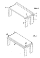
- This unit resembles a four-legged table. Its length, width, and height allow parking of vehicles between its legs while allowing enough space as to conform to all regulations. Along the length of each foot (3) there is a hollow steel pipe which protrudes over the unit (4) as depicted in the figure. On both width sides of the unit's upper part, there is a step (a recess), hereinafter referred to as "the step” (5).
- the four pipes come out of the lower part of the step. As will be exemplified below, this step will allow for the attachment of additional units with the help of the pipes.
- the railing can be an integral part of the unit or be a separate part.
- each pair of legs on the width of the unit can also be attached by a wall, and thus the wall also serves as one large column.
- This unit is identical to the unit T1, except for the following differences: A.
- the step (6) is also located on one length side in addition to the two width sides. The function of this step is to allow the ends of the concrete plates to lean. B. There is no railing.
- each pair of legs on the width of the unit can be combined, and thus the wall created between the legs serves as one large column.
- the units are adjacent to one another along their length (7) with the railing of unit T1 facing outward on one side (8) and the lengthwise step of unit T2 facing the internal facade on the other (9).
- Figure 5 also presents a clear example of the way in which units T1 and T2 can be placed in thc system.
- CP1, CP2 and CP3 units are placed which - in addition to being parts which add to the parking lot's dimensions - serve also for the connection of T1 and T2 units among themselves and between them and other T1 T2 pairs on the level.
- a CP1 unit in the system is composed of a plate made of reinforced concrete which along its length has a railing (10) as exemplified in the figure.
- the railing does not reach the end of the plate, but rather leaves a space (11) on each side.
- Unit CP1 is placed between two T1 items and rests on two steps of adjacent T1 items.
- the width of unit CP1 is smaller than that of unit T1 so that it fits into only part of the widthwise step of unit T1.
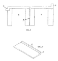
- unit CP2 in the system.
- This unit is comprised of a plate of reinforced concrete such that in the center of each width at appropriate intervals there is a pair of holes (12) and (13) as illustrated in the figure. Through these holes the appropriate protruding pipes of items T1 and T2 will pass (so that the T1 and T2 units will be attached to one another and to unit CP2).
- the CP2 unit is placed between two pairs of T1 T2 units, such that half of it is placed on the widthwise step of the T1 unit and the other half - on the widthwise step of the T2 unit, such that the appropriate pair of pipes of pair T1 T2 passes through it on each width.
- Unit CP3 in the system.
- This unit is composed of a reinforced concrete plate. On both ends of the length there are two holes (16) (17) and a step (18).
- Unit CP3 rests on the two widthwise steps of adjacent T2 units, with the pipes - (18) and (19) fitting into the respective holes (16) and (17).
- the CP unit can also have four holes in four corners.
- This figure describes a side view of units CP1, CP2, and CP3, such that CP1 is the unit facing outward and on whose end there is a railing and CP3 faces the internal facade and on whose edge there is a recess for placing the concrete plates.
- Figure 4 A general side view of the way in which the T2 and CP3 elements are attached is found in Figure 4 ( Figure 13 is an enlargement of the circle which is denoted a number 1 in Figure 4).
- a parking lot can be constructed from a wide variety of other combinations, such as only with type-T tables without connecting plates or with the combination of table-connecting plate-table, with the connecting plate placed parallel to the table. Thus there will be two appropriate tables and two connecting plates or any other combination.
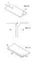
- the L1 unit in the system which is shaped as a long table missing two legs.
- This unit has two legs only on one width side (20), from which two hollow steel pipes protrude and which pass along their length (21).
- a railing (22) along the length of the edge of the "table” plate there is a railing (22), and also on the corner on the side of the railing (as an integral part or seeparately) and opposite the legs - a single hole (23).
- This unit is placed in the system so that on one side it leans on two legs and on the other - it leans on the recess of the T1 unit such that through the hole in it, there passes the appropriate pipe of the T1 unit.
- the width of unit L1 is smaller than the width of unit T1 and identical to that of unit CP1.
- the two legs in the above unit may be connected such that the unit will stand on a wall instead of on two legs. (With regard to the location of unit L1 in the system, see also the general view in Figure 3).
- the modular unit L2 in the system Its shape also resembles an elongated table with two legs missing.
- This unit differs from unit L1 in that the L2 unit does not have a railing, and instead of one hole, it has a pair of holes at the center of the width as illustrated in the figure (24) (25).
- the width of unit L2 is identical to that of unit CP2.
- This unit is placed in the system such that on one side it leans on two legs and on the other - one half leans on the recess of unit T1 and the other on the recess of unit T2, such that a pipe protruding from unit T2 passes through a second hole (25) (and thus it aids in attaching the T1 T2 units).
- the L2 unit is placed like a sandwich between the L1 and L3 units (see also general view in Figure 3).
- L3 in the system. Its shape is also that of an elongated table with two legs missing. It differs from the L1 and L2 units in that along one of its lengths there is a recess (26) which is the beam bearing the concrete plates. In the corner (on the side of the length of the recess) there is a hole (27). This unit, as the two previous ones, can lean on a wall instead of on two legs.
- This unit does not have a railing. and as in the L1 and L2 units along its legs there pass two hollow steel pipes which protrude from it.
- the width of unit L3 is smaller than that of unit T2 to which it is attached and identical to that of unit CP3.
- This unit is placed in the system so that on one side it leans on its two legs, and on the other - it leans on the recess of the T2 unit, with the appropriate protruding pipe in the T2 unit (and the one close to the internal facade) fitting through the hole of unit L3.
- the pair of units T1 T2 are connected to one another on a given level and are inseparable inasmuch as they are connected with the three units - CP1, CP2 and CP3.
- the foundation unit E is a metal cylinder whose bottom is open and whose tope is closed (29). In the lower part there are protruding metal strips (30) whose function it is to anchor this unit more strongly, which is sunken in reinforced concrete which covers most of it up to a level near its upper part (31). From the upper part of the foundation unit there protrudes a hollow pipe (23) which has a cone-shaped opening. The conic opening is anchored to the sides of the unit by means of a metal plate (33).
- the foundation unit there stands a table leg such that the pipe which protrudes on the upper end of the unit enters the conic opening on the bottom of the table leg.
- a taut cable is pulled, the cable is tied to the conic opening of the above foundation units and on the conic opening on the upper end of the structure.
- the cable is pulled from the two extreme conii on the top and on the foundations of the structure.
- the dimension denoted in this figure are for purposes of illustration only.
- the system can be dismantled by detaching the taut cable and separating the units from one another, and transferring the system and constructing it on a new site.
- the units can be permanently attached to one another by pouring concrete into the vertical pipes which pass along the length of the legs of the units. Additional units in the system which is the subject of the present invention and which should be added, especially with regard to a parking lot are those units required for the construction of a ramp for ascent to the parking lot. The details of the ramp are illustrated in Figures 21 through 25.
- the ramp Illustrates a ramp for ascent to the parking lot, to levels two and three.
- the ramp is constructed of four types of units - R1, R2, R3 and R4 - all of which are constructed of reinforced concrete or any other suitable rigid material.
- the vehicle ascends the first half of the slope of the incline.
- a sloped metal surface attached to the concrete and which allows vehicles to ascend on the unit without colliding into the concrete recess.
- unit R2 of the ramp for ascent to the parking lot On this unit the vehicle ascends the second half of the slope of the incline. On each of its sides is a beam which serves also as a railing preventing vehicles from falling (42).
- This unit serves as a surface for entrance and departure of vehicles on the edge of the slope of the ramp. Its shape resembles a table and along its length on the exterior there is a beam which bears the ramp and which also serves as a railing for preventing vehicles from falling (43).
- Unit S1 constitutes steps for the passage of pedestrians from level to level.
- a steel railing can be attached to this item.
- Unit S2 in Figure 26 is a preferred alternative for attaching the stairs in the pre-fabricated system. It is comprised of one unit of poured concrete shaped like stairs, such that on both of its ends there are columns, on its bottom - upwards, and on its upper side - downwards. In these columns, exactly as in the columns of the T tables, there are protruding pipes, and they can fit into any suitable place in the parking lot system, among themselves - as illustrated in Figure 26 or between them and the tables.
- unit S3 in the system. This unit is shaped like an elongated table and its function is to bear S1 when it is necessary to ascend more than one level. Units S1 and S3 can be viewed when integrated in the system in Figure 1.
- the principle on which the invention is based is similar to that of "LEGO: blocks in children's games.
- the units are portable and can be transported from place to place. Structures of any desired area, height, and circumference may be constructed. According to the invention the units may be combined temporarily (by a taut cable) or permanently (by putting concrete in the pipes).
- the preferred material for construction of the units comprising the system is reinforced concrete. bit in principle they may also be made of any other durable and rigid suitable material or any suitable mixture of materials which is strong, stable and durable as is reinforced concrete.
- All the units described heretofore can be also produced without pipes along the length of the columns.
- the system which is the subject of the invention, when of one or two stories, can stand in a stable way also when the units stand on top of each other or side by side without being attached.
- the units can be used without any pipes to create a system of any desired size when conventional methods for the combination of pre-fabricated elements are used, such as tying, screws, welding, soldering, etc. or with pipes without a cable (e.g. up to two stories.
- the units may be used to create a system by using only some of the types of units illustrated according to need, for example - use only of type T units or only of T and CP units.
Applications Claiming Priority (2)
| Application Number | Priority Date | Filing Date | Title |
|---|---|---|---|
| IL91978 | 1989-10-12 | ||
| IL91978A IL91978A (en) | 1989-10-12 | 1989-10-12 | Modular prefabricated structure,the elements comprising it and a method for combining them |
Publications (2)
| Publication Number | Publication Date |
|---|---|
| EP0422915A2 true EP0422915A2 (fr) | 1991-04-17 |
| EP0422915A3 EP0422915A3 (en) | 1992-02-12 |
Family
ID=11060472
Family Applications (1)
| Application Number | Title | Priority Date | Filing Date |
|---|---|---|---|
| EP19900311099 Withdrawn EP0422915A3 (en) | 1989-10-12 | 1990-10-10 | A pre-fabricated modular structure for vehicle parking, elements therefor, and a method for their combination |
Country Status (4)
| Country | Link |
|---|---|
| US (2) | US5177913A (fr) |
| EP (1) | EP0422915A3 (fr) |
| JP (1) | JPH03137362A (fr) |
| IL (1) | IL91978A (fr) |
Cited By (8)
| Publication number | Priority date | Publication date | Assignee | Title |
|---|---|---|---|---|
| WO1992001133A1 (fr) * | 1990-07-12 | 1992-01-23 | A/S Dansk Spændbeton | Parking a plusieurs etages et a planchers constitues de dalles prefabriquees |
| EP0592917A1 (fr) * | 1992-10-12 | 1994-04-20 | Werner Zapf Kg | Installation de garages préfabriqués |
| AU679392B2 (en) * | 1994-11-01 | 1997-06-26 | Robert George Warren | Method and apparatus for constructing a building |
| WO1998015702A1 (fr) * | 1996-10-10 | 1998-04-16 | Bremer Gmbh | Ossature porteuse prefabriquee en beton pour parking a etages |
| EP2105552A2 (fr) | 2003-08-12 | 2009-09-30 | Manchester Cabins Ltd | Plateforme modulaire |
| CN109798000A (zh) * | 2019-03-22 | 2019-05-24 | 常州工学院 | 一种平面移动式模块化智能立体停车库 |
| WO2019122149A1 (fr) * | 2017-12-21 | 2019-06-27 | Laing O'rourke Plc | Structure de plancher démontable |
| EP3833836A4 (fr) * | 2018-08-07 | 2022-04-20 | PRESTON, John Clement | Système de panneau de façade et procédé d'érection d'une structure et d'une façade à plusieurs étages |
Families Citing this family (32)
| Publication number | Priority date | Publication date | Assignee | Title |
|---|---|---|---|---|
| CA2101577C (fr) * | 1992-07-31 | 2005-06-07 | Dale L. Taipale | Scene modulaire portable |
| US5634308A (en) * | 1992-11-05 | 1997-06-03 | Doolan; Terence F. | Module combined girder and deck construction |
| US5277573A (en) * | 1993-03-18 | 1994-01-11 | Thomas Sullivan | Apparatus for fabricating precast concrete ramps |
| US5720135A (en) * | 1994-06-21 | 1998-02-24 | Modular Steel Systems, Inc. | Prefabricated modular vehicle parking structure |
| US5826381A (en) * | 1995-07-10 | 1998-10-27 | Sasaki; Mitsuo | Three-dimensional place-on type assemblable structure |
| US5846020A (en) * | 1997-06-26 | 1998-12-08 | Mckeown; Kevin | Pre-fabricated multi-level roadway structure |
| US6729075B2 (en) | 2000-10-19 | 2004-05-04 | Wenger Corporation | Audience seating system |
| US7874115B2 (en) * | 2003-02-07 | 2011-01-25 | Wenger Corporation | Modular floor |
| US20050072115A1 (en) * | 2003-09-19 | 2005-04-07 | Chappell Ralph Louis | Preformed portable slab for use as a foundation or splash pad for industrial equipment |
| US20050155298A1 (en) * | 2003-10-22 | 2005-07-21 | Atkinson Ross T. | Parking system and structure |
| US20060010621A1 (en) * | 2004-07-19 | 2006-01-19 | Wentz John J | Hybrid modular ramp |
| US20060024149A1 (en) * | 2004-07-28 | 2006-02-02 | Harry Andersen | Method and device for space-saving parking of motor vehicles |
| US20060216111A1 (en) * | 2005-03-22 | 2006-09-28 | Jacky Lam C S | Two-level continuous flow crossroad and construction method and prefabricated parts thereof |
| CN100575644C (zh) * | 2005-12-29 | 2009-12-30 | 陈林 | 标准化城市产品 |
| US20070261335A1 (en) * | 2006-05-08 | 2007-11-15 | Powell David W | Precast construction method and apparatus for variable size elevated platform |
| US8429871B2 (en) * | 2007-04-11 | 2013-04-30 | Erla Dögg Ingjaldsdottir | Affordable, sustainable buildings comprised of recyclable materials and methods thereof |
| US8910439B2 (en) | 2007-04-11 | 2014-12-16 | M3house, LLC | Wall panels for affordable, sustainable buildings |
| US7941975B2 (en) * | 2007-04-11 | 2011-05-17 | Erla Dogg Ingjaldsdottir | Affordable, sustainable buildings comprised of recyclable materials and methods thereof |
| US20090049776A1 (en) * | 2007-08-23 | 2009-02-26 | Matakii O'goshi Lim | Stable and efficient building system |
| DE102009024738A1 (de) * | 2009-06-12 | 2010-12-16 | Adensis Gmbh | Traggerüst für eine Photovoltaikfreiflächenanlage |
| WO2010151539A1 (fr) | 2009-06-22 | 2010-12-29 | Barnet Liberman | Système de construction modulaire pour construire des bâtiments à plusieurs étages |
| WO2011135546A2 (fr) | 2010-04-30 | 2011-11-03 | Paul Friderici | Bâtiment modulaire |
| FR2960865B1 (fr) * | 2010-06-04 | 2014-01-10 | Prefac Beton Environnement | Module de rayonnage |
| CN104343180A (zh) * | 2013-07-28 | 2015-02-11 | 孙善骏 | 筒管状集装组合单元组合体 |
| US9267306B2 (en) * | 2013-08-04 | 2016-02-23 | Avraham Suhami | Multi-storey buildings built over road air-spaces |
| RU2551597C1 (ru) * | 2013-12-13 | 2015-05-27 | Михаил Сергеевич Беллавин | Автостоянка |
| EA201791606A1 (ru) * | 2015-01-15 | 2018-11-30 | Биг Бокс Дайри, Ллс | Сооружения для скота и способы животноводства |
| SG11201901542VA (en) * | 2016-09-23 | 2019-04-29 | Sh Tech Pte Ltd | Construction system and method |
| CN107806264B (zh) * | 2017-09-29 | 2023-12-15 | 中铁科建有限公司 | 一种装配式停车架的工程方法和停车架 |
| US11661712B2 (en) * | 2019-01-15 | 2023-05-30 | Guillermo David Simovich | Smart modular street and sidewalk |
| US11857888B1 (en) * | 2021-03-16 | 2024-01-02 | Sherry Chasteen | Toy gas station playset |
| CN114541465B (zh) * | 2022-03-28 | 2023-08-04 | 中建三局集团有限公司 | 一种可周转的预制装配式钢结构塔吊基础 |
Citations (2)
| Publication number | Priority date | Publication date | Assignee | Title |
|---|---|---|---|---|
| DE1759805B1 (de) * | 1968-06-08 | 1970-01-22 | Bauunternehmung Werner Lutz | Aus Einzelteilen zusammensetzbare und wieder auseinandernehmbare Park- und Abstellflaeche |
| DE7331600U (de) * | 1974-04-04 | Kuehn V | Fertigbauteil für Parkhäuser od. dgl |
Family Cites Families (15)
| Publication number | Priority date | Publication date | Assignee | Title |
|---|---|---|---|---|
| US1886944A (en) * | 1930-04-30 | 1932-11-08 | Ramp Buildings Corp | Building |
| US3510997A (en) * | 1968-08-26 | 1970-05-12 | Eugene Ratych | Building system of preformed units |
| US3566558A (en) * | 1968-10-03 | 1971-03-02 | Joseph V Fisher | Apartment buildings and the like |
| US3653146A (en) * | 1971-02-25 | 1972-04-04 | Adolph E Goldfarb | Modular toy |
| US3813835A (en) * | 1972-05-30 | 1974-06-04 | E Rice | Modular multiple story structure and module therefor |
| US3805461A (en) * | 1972-10-10 | 1974-04-23 | A Jagoda | Modular building system |
| US4104844A (en) * | 1973-09-06 | 1978-08-08 | William Clinton Reid | Method of erecting a building construction |
| US4068425A (en) * | 1977-04-05 | 1978-01-17 | Permacrete Products Corporation | Modular mausoleum |
| LU77983A1 (fr) * | 1977-08-17 | 1978-02-13 | ||
| US4211043A (en) * | 1978-01-06 | 1980-07-08 | Coday Jerry F | Precast concrete building module form |
| DE3309099A1 (de) * | 1983-03-15 | 1984-09-20 | Wilhelm Dipl.-Ing. Dipl.-Kfm. 8960 Kempten Häußler | Autogarage und verfahren zu ihrer herstellung |
| US4694621A (en) * | 1984-11-07 | 1987-09-22 | Locke Reginald A J | Modular building connecting means |
| JPH0615786B2 (ja) * | 1986-04-17 | 1994-03-02 | ジャストジャパン株式会社 | 組立及び載置式立体駐車場構造体 |
| SU1507934A1 (ru) * | 1987-06-10 | 1989-09-15 | Проектный и научно-исследовательский институт "Донецкий ПромстройНИИпроект" | Складной объемный блок здани |
| JPH04502791A (ja) * | 1988-08-02 | 1992-05-21 | ブリティッシュ・テクノロジー・グループ・リミテッド | 建築部材およびその継ぎ手 |
-
1989
- 1989-10-12 IL IL91978A patent/IL91978A/xx not_active IP Right Cessation
-
1990
- 1990-09-25 US US07/587,933 patent/US5177913A/en not_active Expired - Lifetime
- 1990-10-10 EP EP19900311099 patent/EP0422915A3/en not_active Withdrawn
- 1990-10-11 JP JP2275145A patent/JPH03137362A/ja active Pending
-
1992
- 1992-07-31 US US07/922,427 patent/US5305563A/en not_active Expired - Fee Related
Patent Citations (2)
| Publication number | Priority date | Publication date | Assignee | Title |
|---|---|---|---|---|
| DE7331600U (de) * | 1974-04-04 | Kuehn V | Fertigbauteil für Parkhäuser od. dgl | |
| DE1759805B1 (de) * | 1968-06-08 | 1970-01-22 | Bauunternehmung Werner Lutz | Aus Einzelteilen zusammensetzbare und wieder auseinandernehmbare Park- und Abstellflaeche |
Cited By (12)
| Publication number | Priority date | Publication date | Assignee | Title |
|---|---|---|---|---|
| WO1992001133A1 (fr) * | 1990-07-12 | 1992-01-23 | A/S Dansk Spændbeton | Parking a plusieurs etages et a planchers constitues de dalles prefabriquees |
| EP0592917A1 (fr) * | 1992-10-12 | 1994-04-20 | Werner Zapf Kg | Installation de garages préfabriqués |
| AU679392B2 (en) * | 1994-11-01 | 1997-06-26 | Robert George Warren | Method and apparatus for constructing a building |
| WO1998015702A1 (fr) * | 1996-10-10 | 1998-04-16 | Bremer Gmbh | Ossature porteuse prefabriquee en beton pour parking a etages |
| EP2105552A2 (fr) | 2003-08-12 | 2009-09-30 | Manchester Cabins Ltd | Plateforme modulaire |
| EP2105553A2 (fr) | 2003-08-12 | 2009-09-30 | Manchester Cabins Ltd | Plateforme modulaire |
| EP2267247A2 (fr) | 2003-08-12 | 2010-12-29 | Manchester Cabins Ltd | Plate-forme modulaire |
| WO2019122149A1 (fr) * | 2017-12-21 | 2019-06-27 | Laing O'rourke Plc | Structure de plancher démontable |
| CN111566291A (zh) * | 2017-12-21 | 2020-08-21 | 莱恩欧洛克股份有限公司 | 可拆卸楼板结构 |
| EP3833836A4 (fr) * | 2018-08-07 | 2022-04-20 | PRESTON, John Clement | Système de panneau de façade et procédé d'érection d'une structure et d'une façade à plusieurs étages |
| US11808035B2 (en) | 2018-08-07 | 2023-11-07 | John Clement Preston | Facade panel system and method of erecting a multi-storey structure and facade |
| CN109798000A (zh) * | 2019-03-22 | 2019-05-24 | 常州工学院 | 一种平面移动式模块化智能立体停车库 |
Also Published As
| Publication number | Publication date |
|---|---|
| US5305563A (en) | 1994-04-26 |
| JPH03137362A (ja) | 1991-06-11 |
| IL91978A (en) | 1991-12-15 |
| US5177913A (en) | 1993-01-12 |
| EP0422915A3 (en) | 1992-02-12 |
| IL91978A0 (en) | 1990-07-12 |
Similar Documents
| Publication | Publication Date | Title |
|---|---|---|
| EP0422915A2 (fr) | Structure modulaire pour garer des véhicules, éléments pour cela et méthode pour leur assemblage | |
| US5720135A (en) | Prefabricated modular vehicle parking structure | |
| US6101779A (en) | Construction unit for a modular building | |
| US4095380A (en) | Building and elevator module for use therein | |
| US6449791B1 (en) | Prefabricated pier system | |
| US5599006A (en) | Self stable fence | |
| EP0364414A1 (fr) | Construction modulaire pour zones de stationnement, notamment pour zones de stationnement à usage temporaire | |
| EP1554442A2 (fr) | Procede et dispositif de construction utilisant des blocs prefabriques et des elements a ossature | |
| US3707814A (en) | Pre-fabricated stairway | |
| US3136092A (en) | Prefabricated concrete parking structure or the like | |
| US4715159A (en) | Collapsible building construction system | |
| US4640412A (en) | Self-containing package system for storage and transportation of pre-fabricated portions of a building structure and the assembly thereof | |
| US5214817A (en) | Modular ramp and landing walkway assembly | |
| KR0184558B1 (ko) | 조립식 고가도로와 그 시공방법 | |
| GB2074209A (en) | Lattice girder for bridges etc. | |
| US3932970A (en) | Building | |
| JP2020509274A (ja) | 建物構造物 | |
| EP2105552A2 (fr) | Plateforme modulaire | |
| CN111373105B (zh) | 建筑物构造的改进 | |
| JP3245554B2 (ja) | 駐輪場構造物およびその施工法 | |
| WO2008039054A1 (fr) | Dispositif de construction modulaire | |
| KR20070007886A (ko) | 다기능 도시 복합물 | |
| JPH07217230A (ja) | 吊り階段及びその仮設方法 | |
| JPH083611Y2 (ja) | 幅狭な河川、運河等の上方空間を利用する簡易駐車装置を備えた多目的スペース建造物 | |
| JP2769490B2 (ja) | 小規模吊橋のアンカー構造 |
Legal Events
| Date | Code | Title | Description |
|---|---|---|---|
| PUAI | Public reference made under article 153(3) epc to a published international application that has entered the european phase |
Free format text: ORIGINAL CODE: 0009012 |
|
| AK | Designated contracting states |
Kind code of ref document: A2 Designated state(s): AT BE CH DE DK ES FR GB GR IT LI LU NL SE |
|
| PUAL | Search report despatched |
Free format text: ORIGINAL CODE: 0009013 |
|
| AK | Designated contracting states |
Kind code of ref document: A3 Designated state(s): AT BE CH DE DK ES FR GB GR IT LI LU NL SE |
|
| 17P | Request for examination filed |
Effective date: 19920812 |
|
| 17Q | First examination report despatched |
Effective date: 19940113 |
|
| GRAG | Despatch of communication of intention to grant |
Free format text: ORIGINAL CODE: EPIDOS AGRA |
|
| GRAH | Despatch of communication of intention to grant a patent |
Free format text: ORIGINAL CODE: EPIDOS IGRA |
|
| GRAH | Despatch of communication of intention to grant a patent |
Free format text: ORIGINAL CODE: EPIDOS IGRA |
|
| STAA | Information on the status of an ep patent application or granted ep patent |
Free format text: STATUS: THE APPLICATION IS DEEMED TO BE WITHDRAWN |
|
| 18D | Application deemed to be withdrawn |
Effective date: 19970121 |