EP2267247A2 - Plate-forme modulaire - Google Patents
Plate-forme modulaire Download PDFInfo
- Publication number
- EP2267247A2 EP2267247A2 EP10180778A EP10180778A EP2267247A2 EP 2267247 A2 EP2267247 A2 EP 2267247A2 EP 10180778 A EP10180778 A EP 10180778A EP 10180778 A EP10180778 A EP 10180778A EP 2267247 A2 EP2267247 A2 EP 2267247A2
- Authority
- EP
- European Patent Office
- Prior art keywords
- deck
- platform
- module
- deck module
- modular
- Prior art date
- Legal status (The legal status is an assumption and is not a legal conclusion. Google has not performed a legal analysis and makes no representation as to the accuracy of the status listed.)
- Withdrawn
Links
Images


Classifications
-
- E—FIXED CONSTRUCTIONS
- E04—BUILDING
- E04H—BUILDINGS OR LIKE STRUCTURES FOR PARTICULAR PURPOSES; SWIMMING OR SPLASH BATHS OR POOLS; MASTS; FENCING; TENTS OR CANOPIES, IN GENERAL
- E04H6/00—Buildings for parking cars, rolling-stock, aircraft, vessels or like vehicles, e.g. garages
- E04H6/08—Garages for many vehicles
- E04H6/10—Garages for many vehicles without mechanical means for shifting or lifting vehicles, e.g. with helically-arranged fixed ramps, with movable ramps
-
- E—FIXED CONSTRUCTIONS
- E04—BUILDING
- E04B—GENERAL BUILDING CONSTRUCTIONS; WALLS, e.g. PARTITIONS; ROOFS; FLOORS; CEILINGS; INSULATION OR OTHER PROTECTION OF BUILDINGS
- E04B5/00—Floors; Floor construction with regard to insulation; Connections specially adapted therefor
- E04B5/02—Load-carrying floor structures formed substantially of prefabricated units
- E04B5/10—Load-carrying floor structures formed substantially of prefabricated units with metal beams or girders, e.g. with steel lattice girders
-
- E—FIXED CONSTRUCTIONS
- E04—BUILDING
- E04B—GENERAL BUILDING CONSTRUCTIONS; WALLS, e.g. PARTITIONS; ROOFS; FLOORS; CEILINGS; INSULATION OR OTHER PROTECTION OF BUILDINGS
- E04B1/00—Constructions in general; Structures which are not restricted either to walls, e.g. partitions, or floors or ceilings or roofs
- E04B1/18—Structures comprising elongated load-supporting parts, e.g. columns, girders, skeletons
- E04B1/24—Structures comprising elongated load-supporting parts, e.g. columns, girders, skeletons the supporting parts consisting of metal
- E04B1/2403—Connection details of the elongated load-supporting parts
- E04B2001/2463—Connections to foundations
Definitions
- the invention relates to temporary building structures, and particularly those of a portable modular nature whose size can be varied depending upon the requirements of the user.
- the invention describes a modular platform e.g. for use as a temporary (or medium term) solution to car park space shortage.
- the platform may be used to support portable buildings (e.g. portable cabins or offices), such that, for example, both offices and car parking (e.g. under the platform) can be located on the same area of ground.
- portable buildings e.g. portable cabins or offices
- both offices and car parking e.g. under the platform
- Such a solution is particularly advantageous in situations where there is a shortage of space and is particularly useful if the platform is erected over an existing car park.
- EP0422915 (Erel ) teaches a multi-storey structure having pre-fabricated units of a modular construction
- US 5720135 (Paquette ) shows a vehicle parking structure having a steel framework with a grid of support beams for holding a number of modular deck panels.
- the problems associated with such structures include the need to strike a balance between portability, ease/speed of construction and structural strength, i.e. the ability of a temporary structure (i.e. one without foundations) to support the weight of a load mounted on it (e.g. a number of parked vehicles). It is known to provide 'quasi-foundations' by embedding at least a portion of a support column in the ground to stabilise the whole construction. However, this clearly defeats the very object of having a temporary and portable structure. Most previous attempts (e.g. Erel and Paquette) provide a grid of columns, where each modular plate which makes up the deck structure is supported on each of its corners.
- the present invention provides a temporary portable platform, suitable for use as a car park, that can be erected over an area (e.g. a ground level car park) to add an extra level e.g. for car parking, locating of portable buildings or the like.
- the platform clearly has many potential uses, e.g. for storage or large containers or in any application where more space is required but available land is limited.
- the platform is made of modular units shaped to be both easy to transport and quick to erect.
- the modular units are shaped and constructed such that the entire platform may need only to be supported along two of its edges. This construction is useful because it allows good access to the underside of the platform and the underside itself does not have any columns which may hinder its use.
- a modular platform suitable for supporting vehicles or portable buildings or the like having: a plurality of deck modules, each deck module being a prefabricated unit for forming a part of the deck of the modular platform, each deck module being attached to at least one other deck module and including a deck surface suitable for vehicle parking on; and support means attached to the platform for supporting it above an area; wherein the deck surface of each deck module is substantially rectangular, the deck surface having a support space (suitable for supporting a vehicle or a portable building or the like) located at each of the longitudinally opposite ends, and an aisle space between the support spaces suitable for allowing passage of traffic.
- the present invention thus provides a platform made up of deck modules each of which has more than one car parking space on it. Of course, the spaces need not be used solely for car parking; each car parking space may be used for car or pedestrian management.
- the deck modules may be the smallest components that make up the surface of the platform. They are prefabricated units, i.e. they are not easily disassembled into further pieces. They are intended as the building blocks of the platform to be used on site. To make them smaller would require a cutting torch or the like.
- the deck modules may be supported at or near their corners, which means that fewer supporting columns are required than in known constructions.
- the span of the deck modules may be greater than those in the prior art, thereby allowing the underside of the platform to be used more effectively, including use as a car park.
- the deck modules may vary in length to include further parking spaces or a wider aisle space.
- the deck module may be of a size that allows for a standard multi-storey car park layout.
- the entire platform may be metal (e.g. steel).
- the support means include a plurality of legs mounted only on two opposite edges on the platform, such that there are no legs located underneath the surface of the platform.
- the legs are located towards the outside edges of the platform like a simple table (so that they can be accessed easily without the need to go substantially under the platform itself).
- they are mounted on the platform in a location in which they can be positioned by e.g. a crane. Locating the legs on two opposite edges of the platform has two clear advantages. Firstly, as mentioned above, if there are no legs located under the platform, its versatility for use is increased. The second advantage comes in erecting the platform. The legs may be heavy and require machinery to make them upright.
- each leg is mounted on the edges defined by the longitudinally opposite ends of the deck modules.
- each leg is attachable to a deck module at or near its corners.
- the length of the short side of the deck module is the width of a parking space. This enables the platform to be more easily erected over existing car parks, and it is an efficient way of constructing the platform, because the number of modules corresponding exactly to a discrete number of parking spaces.
- the width of the aisle space is two traffic lanes. This allows a two-way traffic flow on the surface of the platform, as well as providing more space for parking manoeuvres.
- the width of the surface may be less than 3 metres. Preferably, it is less than 2.6 metres. It may be more than 2 metres. Preferably, it is more than 2.3 metres. Most preferably, the width of the surface is 2.4 metres (approximately 8 feet).
- the length of the surface may be less than 20 metres. Preferably, it is less than 16.0 metres. It may be more than 15 metres. Preferably, it is more than 15.7 metres. Most preferably, the length of the surface is 15.85 metres (approximately 52 feet).
- the depth of the deck module may be less than 1 metre. Preferably, it is less than 0.75m. Most preferably, it is 0.6m (about 2 feet).
- the official size of car parking bays in the UK is 2.4m x 4.8m, and the width of road space between two opposite car parking spaces may be 6 metres.
- the preferred dimensions of the deck module allows for two opposite car parking spaces separated by an aisle space with a width of about 6 metres.
- the dimensions of the deck module may be such that it is loadable on a lorry without exceeding the wide load limit.
- the dimensions of the deck module are such that four modules are loadable on a lorry without exceeding the wide load limit.
- the deck modules may weigh up to 6 tons, so up to five modules may be stacked on a lorry (the lorry may have an extendable trailer).
- the wide load limit i.e. the width of a vehicle which must be notified to the police in the UK and may be subject to time and/or route restrictions is 9 feet 6 inches (about 2.9 metres).
- the width of the module of the present invention is preferably less than this value, yet preferably more than the required width of a car park space.
- the deck module is attachable to further deck modules along the longer side of the surface.
- the deck modules will be held together by nuts and bolts to make the site erection easy.
- a crane may be used to suspend a deck module over the area it is to cover, whilst the support means are arranged below it and connected to it.
- each leg is attachable to two deck modules.
- the initial deck module will require four legs (one at each corner), whereas each additional deck module will only require two further legs because it can also rest on two of the legs already attached to a deck module that is part of the platform. This improves the efficiency of construction, and of course reduces the number of parts required.
- each leg has a support ledge for e.g. temporarily resting the deck module on.
- the support ledge may be used for aligning the bolt holes on the deck module with those on the leg.
- each leg has a foot for resting on the ground.
- the foot may rest on an e.g. steel plate to spread the load of the platform. This plate will evenly distribute the weight of the platform over a larger area. This distribution of weight also negates the requirement for foundations if the ground is deemed sound enough.
- the attachment between at least one foot and its respective leg allows the leg, when upright, to move relative to the ground as the platform is loaded.
- the present invention proposes a solution where some or preferably all of the legs on at least one side of the platform are mounted on feet in such a way to allow motion of the leg, so that the leg remains substantially vertical whatever load is on the platform. This clearly maintains the structural strength of the platform better than legs which bend away from the vertical.
- all the legs along one edge of the platform are movable relative to the ground as the platform is loaded. It may be possible to make all the legs movable, but the amount of flexing required by e.g. a single deck car park means that the legs on only one side need to be movable to compensate. Thus, the legs attached to the other edge may be fixed (at least horizontally) with respect to their feet.
- the foot allowing movement of its respective leg is pivotably attached to the leg.
- the foot has a curved surface for contacting the ground, so that it will rock on this surface as the leg moves relative to the ground.
- the legs are capable of automatically adjusting when the platform is loaded and unloaded.
- the legs are also length adjustable to enable erection of the platform on uneven ground.
- the length adjustment may be by means of an integral jacking mechanism.
- the legs may also be adjusted later in the case of differential settlement.
- the modular platform includes access means attached to it for allowing access to its surface.
- the access means includes a ramp having a main path leading up to the surface of the deck module.
- the ramp is preferably of a length that allows it to be transported in a standard manner on a lorry.
- the ramps may include kerbs and guard rails to guide traffic and straying pedestrians up or down the ramp.
- the access means includes two ramps attached to the platform, one ramp for accessing the surface and one ramp for exiting the surface.
- the dimensions of these ramps are preferable such that they can both be loaded on a single lorry without exceeding the wide load limit.
- the or each ramp may have a length of about 18 metres (60 feet).
- the width of the or each ramp is preferably less than 2.9m (9 feet 6 inches) to enable loading on a lorry without exceeding the wide load limit.
- the width is preferably about 2.87 metres (9 feet 5 inches).
- the ramp(s) are attached to the deck module adjacent the aisle space.
- the traffic can drive straight from the ramp into the aisle space for easy access to a parking space.
- the access means may include a staircase to allow people access to the surface of the deck module.
- the surface of the deck module is cambered.
- the camber may be for permitting rain run off.
- the camber may be effected by the deck module including at least one bowed beam (made of e.g. steel) which extends along the entire length of the deck module and supports its surface.
- the bowed beam may be manufactured from a straight beam.
- the deck module has three bowed beams.
- the beams are steel beams.
- the camber may be less than 1:100. Preferably, it is about 1:150.
- the surface of the platform may not be waterproof, therefore the camber need not be at the standard camber for rain run off.
- the deck module includes a lifting bracket located towards each corner of for facilitating suspension of the deck module using a crane.
- the lifting bracket may also be used as a locking mechanism to fix the decks together when they are stacked on a lorry during transportation.
- a modular platform suitable for supporting vehicles or portable buildings or the like having: a plurality of deck modules, each deck module being a prefabricated unit for forming a part of the deck of the modular platform, each deck module being attached to at least one other deck module and including a deck surface suitable for vehicle parking on; and support means attached to the platform for supporting it over an area; wherein the support means includes a leg having a foot for resting on the ground, the attachment between the foot and the leg allowing the leg, when upright, to move laterally relative to the ground and/or foot as the platform is loaded.
- the leg is movable when the platform is loaded, thereby avoiding buckling.
- the legs attached to the platform are arranged so that one or more of them can move relative (i.e. towards or away from) the others.
- the platform may automatically adjust as it is unloaded or loaded due to the movable leg or legs.
- the present invention provides as an independent concept the idea of a modular platform having legs which can move laterally with respect to the ground whilst remaining upright.
- the joint between the top of the leg and the platform must have a degree of flexibility to allow the leg to remain substantially vertical as the surface flexes. This is allowed by the bolting method of the present invention, although there are of course other ways to achieve it. All the features described above may provided as additional or optional features of such a modular platform.
- the support means may include a plurality of legs mounted only on two opposite edges on the platform and all the legs along one edge of the platform may be movable relative to the ground as the platform is loaded.
- the present invention also provides in a further aspect a kit for constructing a modular platform suitable for supporting vehicles or portable buildings or the like, the kit including: one or more deck modules, each deck module being a prefabricated unit for forming a part of the deck of the modular platform, each deck module being attachable to at least one other deck module and including a deck surface suitable for vehicle parking on; and support means attachable to the platform for supporting it above an area; wherein the deck surface of each deck module is substantially rectangular, the deck surface having a support space (suitable for supporting a vehicle or a portable building or the like) located at each of the longitudinally opposite ends, and an aisle space between the support spaces suitable for allowing passage of traffic.
- a support space suitable for supporting a vehicle or a portable building or the like
- the present invention also provides in yet further aspect a kit for constructing a modular platform suitable for supporting vehicles or portable buildings or the like, the kit having: one or more deck modules, each deck module being a prefabricated unit for forming a part of the deck of the modular platform, each deck module being attachable to at least one other deck module and including a deck surface suitable for vehicle parking on; and support means attachable to the platform for supporting it over an area; wherein the support means includes a leg having a foot for resting on the ground, the attachment between the foot and the leg allowing the leg, when upright, to move laterally relative to the ground and/or foot as the platform is loaded.
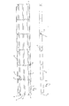
- Fig. 1 shows the underside of a deck module for use in a modular platform according to the present invention.
- the dimensions of the module as shown in Fig. 1 are 52 feet ⁇ 8 feet (15.85 ⁇ 2.44 metres).
- the module has three deck beams 1 extending the entire length of the module.
- Each deck beam 1 is a bowed e.g. steel beam, as can be seen from Fig. 2 .
- the beam may be initially straight.
- the steel beam is bowed by heating the centre section while the beam is bent in a hydraulic press.
- the cut is welded up to form a join 9.
- the bowed beams 1 give the deck module its camber.
- the three deck beams 1 are interconnected by deck cross members 2; each end of each cross member 2 is e.g. welded to a support plate 3, which is e.g. bolted to the deck beam 1.
- the three deck beams 1 are substantially parallel, and form the backbone of the deck module.
- the side edges of the module are made up of deck side angles 5, each of which is attached to an adjacent deck beam 1 by a deck outrigger 4.
- the attachment between the outermost deck beam 1 and the deck side angle 5 is shown in more detail in Fig. 3 .
- deck outrigger 4 is e.g. welded to a support plate 3, which e.g. bolted to the deck beam 1.
- the deck side angle 5 has a number of support angles 11 welded to it to correspond to the positions of the deck outriggers 4 on the deck beam 1.
- the support angles 11 are bolted to the deck outriggers 4 such that the top edge of deck side angle 5 is at the same level as the top edge of the deck beam 1.
- Sheet metal 12 e.g. steel
- anti-slip sheets e.g. of steel
- the upright edges of deck side angles 5 have holes through them which can be aligned with holes on corresponding edges of other deck modules to enable them to be bolted together.
- the deck beams 1 have deck end angles 6 bolted to them to allow an end plate 7 to be e.g. bolted on.
- Each deck beam 1 has two deck end angles 6 at each end.
- Each end plate 7 has two lifting brackets 8 bolted to it.
- Fig. 4 shows how the lifting brackets 8 can be attached to a crane 13 for lifting and positioning the deck module e.g. during erection.
- the lifting brackets 8 may also be bolted together to form a locking mechanism when the decks are stacked on a lorry during transportation.
- Fig. 2 shows a longitudinal cross section along line A-A on Fig. 1 .
- the deck outriggers 4 are in fact angles. This is to improve access for an impact wrench to the bolt holes through the deck side angles 5.
- Fig. 2 also shows the holes 10 in the deck beam for attaching the deck end angles 6.
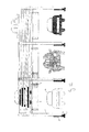
- Fig. 5 shows an end view of the deck module positioned in a modular platform (although there are no additional modules shown attached to its longitudinal edges).
- the bottom edge of the module rests on angled supports 15, which are welded to legs 14.
- the deck module is bolted to the legs 14 via holes in the legs which correspond to holes in the end plate 7.
- the legs 14 extend below the deck module to hold it above the ground. They also extend above the surface of the deck module to provide posts to which barriers can be attached.
- the barriers may include cross bars 17 for preventing people from falling over the edge of the deck module and a crash barrier 16 for stopping e.g. cars from doing likewise.
- the deck module shown in Figs. 1 to 5 is intended to be used with other modules to create a larger area. As such, its longitudinal sides contain no barriers or posts which would restrict the amount of parking space or manoeuvrability on the surface. However, the edge of the composite platform will need to have a barrier, and Fig. 6 shows a deck module that could be positioned at the end of a platform. Parts which are in common with the module shown in Fig. 1 have the same reference numerals. The difference here comes in the outrigger assemblies 20, 21 on one longitudinal side of the deck module. These outrigger assemblies include a thicker deck outrigger 20 which extends beyond the edge of the deck side angle 5 and has an upright port 21 attached to it. Fig. 7 shows the arrangement in more detail.
- the outrigger 20 is welded to a support plate 33 (which is generally larger than support 3 to cope with the additional load), which is bolted to the deck beam 1.
- the deck side angle 5 and support angle 11 are connected as before, and upright post 21 is welded to the end of outrigger 20 which extends beyond the side of the deck side angle 5.
- the central post may have a larger support plate 34. Of course, this post may be omitted to allow access ramp to be mounted in this location (see e.g. Fig. 13 ).
- the legs shown in Figs. 5 and 8 include pairs of holes located along their length. As shown in Figs. 5 and 8 , only one side of these hole parts are needed to attach a deck module and barriers corresponding to that deck module to a leg. The other holes allow a further deck module (and barriers) to be attached to the other side of the leg. Thus, one leg can be attached to two deck modules. For example, holes 18 in Fig. 5 allow a deck module parallel to the one shown in the drawing to be attached to that leg. Holes 19 are for attaching a diagonal support member 26 (e.g. shown in Fig. 11). Fig. 11 shows a cross-sectional view of a deck module mounted to form a platform.
- the module is long enough to permit two cars 27a, 27b to park facing inwards whilst leaving enough room (an aisle space) for two lanes of traffic between them.
- Fig. 11 also shows the connection between the leg 14 and the ground.
- a foot assembly 35 which includes an ankle member 25 bolted via attachment plates 28 to leg 14, the base of the ankle member being pivotably attached to a foot 22 located on a plate 24.
- the ankle member 25 may include a jack for adjusting the length of the leg to allow the platform to be erected on uneven ground.
- the ankle member may be a telescopic landing gear such as the type manufactured by Jost GB Ltd. Such landing gears are usually used in pairs to unhook and support the trailers of articulated lorries. These landing gears are provided with pivotable feet to cater for forward movement of the trailer when air is let out of its suspension systems.
- the pivotable foot 22 is shown in more detail in Fig. 9 .
- the foot has a curved surface 36 for contacting the ground. It also includes two holes 23 for attaching to the ankle member 25 (which may include an integral jacking mechanism) and which define the pivoting axis.
- the foot 22 is generally mounted on a base plate 24 for spreading the load of the platform over a larger area. This is especially important on softer ground, and means foundations are not required. Foot 22 may rock in its own bracket (not shown) which can then be mounted on a base plate 24.
- Figs. 10a and 10b show the motion of the foot when the leg moves sideways.
- the surface flexes, which forces apart the supporting legs.
- this results in tension building up in them as they are bent by the load. This tension and bending can lead to weakness and buckling.
- the legs on rocking feet are permitted to move, as shown in Fig. 10b .
- the foot 22 rocks about its axis, the curved surface 36 remaining in contact with the ground the whole time.
- the leg will return to its previous position, thus the legs are automatically adjustable to the amount of load on the platform.
- Fig. 12 shows three deck modules attached to one another. As mentioned previously, there is only one leg at the junction between the corners of two deck modules. The distance between adjacent legs also enables a vehicle (e.g. a car) to pass through.
- a vehicle e.g. a car
- Fig. 13 shows the side view of one end of a modular platform, where part of the barriers have been removed to allow ramps 29 to be attached to the surface of the platform.
- Two ramps are shown to give separate routes for vehicles entering and exiting the platform.
- the ramps 29 include kerbs 30 at either side of the trade leading up to the platform surface. These prevent vehicles from accidentally driving off the edge of the ramps.
- a pedestrian staircase 31 is also mounted to the edge of the deck module. This enables people to gain access to the platform surface without having to use the vehicle ramps 29.
- the ramps are shown attached to the centre of the longitudinal side of the endmost deck module, it is clear that there could equally well be attached at any other point on the platform.
- the ramps are the same width as the deck modules, so it may even be possible to attach them directly to a lateral end of a deck module.
- Figs. 11 , 12 and 13 also show the jacking, levelling and leg rocking mechanisms of the foot assembly.
- Fig. 14 shows a overall top view of a constructed platform used as a portable car park.
- Figs. 15a and 15b show side views of a constructed platform used as a car park in a partially loaded and unloaded state respectively.
Applications Claiming Priority (3)
| Application Number | Priority Date | Filing Date | Title |
|---|---|---|---|
| GB0318914A GB2404928B (en) | 2003-08-12 | 2003-08-12 | Modular platform |
| EP04254321A EP1507053B1 (fr) | 2003-08-12 | 2004-07-19 | Plateforme modulaire |
| EP09008668.7A EP2105553A3 (fr) | 2003-08-12 | 2004-07-19 | Plateforme modulaire |
Related Parent Applications (5)
| Application Number | Title | Priority Date | Filing Date |
|---|---|---|---|
| EP04254321A Division EP1507053B1 (fr) | 2003-08-12 | 2004-07-19 | Plateforme modulaire |
| EP04254321.5 Division | 2004-07-19 | ||
| EP09008668.7A Division EP2105553A3 (fr) | 2003-08-12 | 2004-07-19 | Plateforme modulaire |
| EP09008668.7A Division-Into EP2105553A3 (fr) | 2003-08-12 | 2004-07-19 | Plateforme modulaire |
| EP09008668.7 Division | 2009-07-02 |
Publications (2)
| Publication Number | Publication Date |
|---|---|
| EP2267247A2 true EP2267247A2 (fr) | 2010-12-29 |
| EP2267247A3 EP2267247A3 (fr) | 2014-01-15 |
Family
ID=28052363
Family Applications (4)
| Application Number | Title | Priority Date | Filing Date |
|---|---|---|---|
| EP09008668.7A Withdrawn EP2105553A3 (fr) | 2003-08-12 | 2004-07-19 | Plateforme modulaire |
| EP04254321A Active EP1507053B1 (fr) | 2003-08-12 | 2004-07-19 | Plateforme modulaire |
| EP10180778.2A Withdrawn EP2267247A3 (fr) | 2003-08-12 | 2004-07-19 | Plate-forme modulaire |
| EP09008666.1A Withdrawn EP2105552A3 (fr) | 2003-08-12 | 2004-07-19 | Plateforme modulaire |
Family Applications Before (2)
| Application Number | Title | Priority Date | Filing Date |
|---|---|---|---|
| EP09008668.7A Withdrawn EP2105553A3 (fr) | 2003-08-12 | 2004-07-19 | Plateforme modulaire |
| EP04254321A Active EP1507053B1 (fr) | 2003-08-12 | 2004-07-19 | Plateforme modulaire |
Family Applications After (1)
| Application Number | Title | Priority Date | Filing Date |
|---|---|---|---|
| EP09008666.1A Withdrawn EP2105552A3 (fr) | 2003-08-12 | 2004-07-19 | Plateforme modulaire |
Country Status (4)
| Country | Link |
|---|---|
| EP (4) | EP2105553A3 (fr) |
| AT (1) | ATE441768T1 (fr) |
| DE (1) | DE602004022899D1 (fr) |
| GB (4) | GB2404928B (fr) |
Families Citing this family (7)
| Publication number | Priority date | Publication date | Assignee | Title |
|---|---|---|---|---|
| GB0701838D0 (en) * | 2007-01-31 | 2007-03-14 | Hill & Smith Infrastructure Pr | Modular car park deck |
| GB2457907A (en) * | 2008-02-28 | 2009-09-02 | Portasilo Ltd | Raised car parking platform |
| ES2312289B1 (es) * | 2008-04-16 | 2009-10-13 | Simulpal S.L.U. | Sistema de aparcamiento en altura. |
| AU2013207597B2 (en) * | 2013-07-17 | 2018-05-31 | Capital Project Management Pty Ltd | A modular temporary car park assembly |
| US20180371780A1 (en) * | 2017-06-27 | 2018-12-27 | Doxa Central, L.L.C. | Methods and Apparatus for a Modular Parking System |
| CN108915325B (zh) * | 2018-08-20 | 2020-12-11 | 佛山市诺行科技有限公司 | 一种底坑简易升降停车设备 |
| CN115288499B (zh) * | 2022-08-08 | 2023-06-23 | 中铁二院工程集团有限责任公司 | 一种快速交通系统的车站结构 |
Citations (4)
| Publication number | Priority date | Publication date | Assignee | Title |
|---|---|---|---|---|
| US4277921A (en) * | 1977-04-06 | 1981-07-14 | Velo Dalbrenta Gianfranco | Three-dimensional componental module at "T" modified for the industrial preformation of buildings |
| EP0422915A2 (fr) | 1989-10-12 | 1991-04-17 | Yigal Erel | Structure modulaire pour garer des véhicules, éléments pour cela et méthode pour leur assemblage |
| US5720135A (en) | 1994-06-21 | 1998-02-24 | Modular Steel Systems, Inc. | Prefabricated modular vehicle parking structure |
| GB2350132A (en) | 1998-03-05 | 2000-11-22 | David Stern | Demountable modular deck |
Family Cites Families (8)
| Publication number | Priority date | Publication date | Assignee | Title |
|---|---|---|---|---|
| US3708933A (en) * | 1971-07-16 | 1973-01-09 | Y Yang | Demountable garage building |
| US4930809A (en) * | 1988-01-11 | 1990-06-05 | Lindsay Industries, Inc. | Towable unified floor frame assembly |
| ES2033138T3 (es) * | 1988-10-06 | 1993-03-01 | Centro Progettazioni Coordinate S.R.L | Estructura modular para aparcamientos, particularmente adecuada para aparcamientos provisionales. |
| FR2642784A1 (fr) * | 1989-02-08 | 1990-08-10 | Martinez Alphonse | Parking modulaire pour vehicules automobiles |
| NO890842L (no) * | 1989-02-28 | 1990-08-30 | Per K Olsen | Byggeelementer for bygging av parkeringshus eller lignende |
| GB2229203A (en) * | 1989-03-10 | 1990-09-19 | Car Parking Services Limited | Multi-storey steel building |
| AU645756B2 (en) * | 1989-08-17 | 1994-01-27 | Bhp Engineering Proprietary Limited | Car park |
| FR2740489B1 (fr) * | 1995-10-30 | 1998-01-16 | Chamboux Pierre | Bacs acier galvanise autoportant pour la construction de parcs a voitures legeres sur deux niveaux |
-
2003
- 2003-08-12 GB GB0318914A patent/GB2404928B/en not_active Expired - Lifetime
- 2003-08-12 GB GB0609885A patent/GB2426769B/en not_active Expired - Lifetime
- 2003-08-12 GB GB0609881A patent/GB2426767B/en not_active Expired - Lifetime
- 2003-08-12 GB GB0609883A patent/GB2426768B/en not_active Expired - Lifetime
-
2004
- 2004-07-19 EP EP09008668.7A patent/EP2105553A3/fr not_active Withdrawn
- 2004-07-19 EP EP04254321A patent/EP1507053B1/fr active Active
- 2004-07-19 EP EP10180778.2A patent/EP2267247A3/fr not_active Withdrawn
- 2004-07-19 EP EP09008666.1A patent/EP2105552A3/fr not_active Withdrawn
- 2004-07-19 AT AT04254321T patent/ATE441768T1/de not_active IP Right Cessation
- 2004-07-19 DE DE602004022899T patent/DE602004022899D1/de active Active
Patent Citations (4)
| Publication number | Priority date | Publication date | Assignee | Title |
|---|---|---|---|---|
| US4277921A (en) * | 1977-04-06 | 1981-07-14 | Velo Dalbrenta Gianfranco | Three-dimensional componental module at "T" modified for the industrial preformation of buildings |
| EP0422915A2 (fr) | 1989-10-12 | 1991-04-17 | Yigal Erel | Structure modulaire pour garer des véhicules, éléments pour cela et méthode pour leur assemblage |
| US5720135A (en) | 1994-06-21 | 1998-02-24 | Modular Steel Systems, Inc. | Prefabricated modular vehicle parking structure |
| GB2350132A (en) | 1998-03-05 | 2000-11-22 | David Stern | Demountable modular deck |
Non-Patent Citations (1)
| Title |
|---|
| "Suffolk Advisory Parking Standards", 30 April 2002 (2002-04-30), XP055168935, Retrieved from the Internet <URL:http://www.suffolkcoastal.gov.uk/assets/Documents/District/Planning-policy/SPG/SPG3SuffolkAdvisoryParkingStandards.pdf> [retrieved on 20150211] * |
Also Published As
| Publication number | Publication date |
|---|---|
| GB0609885D0 (en) | 2006-06-28 |
| EP1507053A3 (fr) | 2005-12-14 |
| GB2426767B (en) | 2007-05-09 |
| EP2267247A3 (fr) | 2014-01-15 |
| GB2426767A (en) | 2006-12-06 |
| EP1507053B1 (fr) | 2009-09-02 |
| GB2426769B (en) | 2007-05-09 |
| ATE441768T1 (de) | 2009-09-15 |
| GB2426768B (en) | 2007-05-09 |
| EP2105553A3 (fr) | 2014-01-15 |
| GB0318914D0 (en) | 2003-09-17 |
| DE602004022899D1 (de) | 2009-10-15 |
| GB2426769A (en) | 2006-12-06 |
| GB2404928B (en) | 2007-05-09 |
| GB2404928A (en) | 2005-02-16 |
| EP2105552A2 (fr) | 2009-09-30 |
| GB2426768A (en) | 2006-12-06 |
| EP2105553A2 (fr) | 2009-09-30 |
| EP1507053A2 (fr) | 2005-02-16 |
| GB0609883D0 (en) | 2006-06-28 |
| GB0609881D0 (en) | 2006-06-28 |
| EP2105552A3 (fr) | 2014-01-15 |
Similar Documents
| Publication | Publication Date | Title |
|---|---|---|
| US7971408B2 (en) | Stairtower and method for erecting the same | |
| JP2774143B2 (ja) | 車両駐車装置 | |
| US5720135A (en) | Prefabricated modular vehicle parking structure | |
| US6467223B1 (en) | Composite concrete and steel floor/carrier for modular buildings | |
| WO2008093081A2 (fr) | Plate-forme modulaire de stationnement de voitures | |
| US7325362B1 (en) | Steel roof truss system | |
| EP1507053B1 (fr) | Plateforme modulaire | |
| EP0185484A2 (fr) | Système d'éléments de structure formant leur propre emballage pour l'entreposage et le transport et assemblage de ces éléments | |
| EP3286390B1 (fr) | Colonne améliorée pour la réalisation de structures préfabriquées, en particulier pour la réalisation de stationnements modulaires | |
| KR200187693Y1 (ko) | 조립식 가설대 | |
| EP1355020A2 (fr) | Structure de garage de véhicules auto-portante et modulaire | |
| US20050252150A1 (en) | Module based building system | |
| CN109267820B (zh) | 一种模块化附带参观走道活动围挡及安装方法 | |
| US4679374A (en) | Building construction method | |
| JP3241196B2 (ja) | 装置搭載用据付け台 | |
| JP3736893B2 (ja) | ユニット式建物の屋根構造 | |
| JP4257153B2 (ja) | 屋外階段及び屋外階段の構築方法 | |
| ITRM20060054A1 (it) | Struttura modulare smontabile per lo stoccaggio intensivo di autoveicoli su due livelli | |
| WO2012108779A1 (fr) | Bâtiment et procédé de construction d'un bâtiment | |
| MXPA06006935A (es) | Sistema elevador y posicionador de materiales para usarse en edificacion para el sector, vivienda, turismo, industrial, comercial y construccion en general. | |
| GB2365883A (en) | Load-bearing structure | |
| CN115478724A (zh) | 新型自走式钢结构立体车库 | |
| CA3235346A1 (fr) | Batiment pour parcs de stationnement de vehicules | |
| WO2023242470A1 (fr) | Abri balistique et procédé de fabrication d'un abri balistique | |
| WO2022061393A1 (fr) | Unité de bâtiment modulaire et bâtiment et procédé de construction associés |
Legal Events
| Date | Code | Title | Description |
|---|---|---|---|
| PUAI | Public reference made under article 153(3) epc to a published international application that has entered the european phase |
Free format text: ORIGINAL CODE: 0009012 |
|
| AC | Divisional application: reference to earlier application |
Ref document number: 1507053 Country of ref document: EP Kind code of ref document: P Ref document number: 2105553 Country of ref document: EP Kind code of ref document: P |
|
| AK | Designated contracting states |
Kind code of ref document: A2 Designated state(s): AT BE BG CH CY CZ DE DK EE ES FI FR GB GR HU IE IT LI LU MC NL PL PT RO SE SI SK TR |
|
| AX | Request for extension of the european patent |
Extension state: AL HR LT LV MK |
|
| PUAL | Search report despatched |
Free format text: ORIGINAL CODE: 0009013 |
|
| AK | Designated contracting states |
Kind code of ref document: A3 Designated state(s): AT BE BG CH CY CZ DE DK EE ES FI FR GB GR HU IE IT LI LU MC NL PL PT RO SE SI SK TR |
|
| AX | Request for extension of the european patent |
Extension state: AL HR LT LV MK |
|
| RIC1 | Information provided on ipc code assigned before grant |
Ipc: E04H 6/10 20060101AFI20131209BHEP |
|
| 17P | Request for examination filed |
Effective date: 20140710 |
|
| RBV | Designated contracting states (corrected) |
Designated state(s): AT BE BG CH CY CZ DE DK EE ES FI FR GB GR HU IE IT LI LU MC NL PL PT RO SE SI SK TR |
|
| 17Q | First examination report despatched |
Effective date: 20150217 |
|
| STAA | Information on the status of an ep patent application or granted ep patent |
Free format text: STATUS: THE APPLICATION IS DEEMED TO BE WITHDRAWN |
|
| 18D | Application deemed to be withdrawn |
Effective date: 20170919 |