EP0419809B1 - Clenche pour véhicule - Google Patents
Clenche pour véhicule Download PDFInfo
- Publication number
- EP0419809B1 EP0419809B1 EP90114655A EP90114655A EP0419809B1 EP 0419809 B1 EP0419809 B1 EP 0419809B1 EP 90114655 A EP90114655 A EP 90114655A EP 90114655 A EP90114655 A EP 90114655A EP 0419809 B1 EP0419809 B1 EP 0419809B1
- Authority
- EP
- European Patent Office
- Prior art keywords
- damping element
- door handle
- actuating lever
- handle according
- lever
- Prior art date
- Legal status (The legal status is an assumption and is not a legal conclusion. Google has not performed a legal analysis and makes no representation as to the accuracy of the status listed.)
- Expired - Lifetime
Links
Images
Classifications
-
- E—FIXED CONSTRUCTIONS
- E05—LOCKS; KEYS; WINDOW OR DOOR FITTINGS; SAFES
- E05B—LOCKS; ACCESSORIES THEREFOR; HANDCUFFS
- E05B77/00—Vehicle locks characterised by special functions or purposes
- E05B77/42—Means for damping the movement of lock parts, e.g. slowing down the return movement of a handle
-
- E—FIXED CONSTRUCTIONS
- E05—LOCKS; KEYS; WINDOW OR DOOR FITTINGS; SAFES
- E05B—LOCKS; ACCESSORIES THEREFOR; HANDCUFFS
- E05B85/00—Details of vehicle locks not provided for in groups E05B77/00 - E05B83/00
- E05B85/10—Handles
-
- Y—GENERAL TAGGING OF NEW TECHNOLOGICAL DEVELOPMENTS; GENERAL TAGGING OF CROSS-SECTIONAL TECHNOLOGIES SPANNING OVER SEVERAL SECTIONS OF THE IPC; TECHNICAL SUBJECTS COVERED BY FORMER USPC CROSS-REFERENCE ART COLLECTIONS [XRACs] AND DIGESTS
- Y10—TECHNICAL SUBJECTS COVERED BY FORMER USPC
- Y10S—TECHNICAL SUBJECTS COVERED BY FORMER USPC CROSS-REFERENCE ART COLLECTIONS [XRACs] AND DIGESTS
- Y10S292/00—Closure fasteners
- Y10S292/56—Silencers
-
- Y—GENERAL TAGGING OF NEW TECHNOLOGICAL DEVELOPMENTS; GENERAL TAGGING OF CROSS-SECTIONAL TECHNOLOGIES SPANNING OVER SEVERAL SECTIONS OF THE IPC; TECHNICAL SUBJECTS COVERED BY FORMER USPC CROSS-REFERENCE ART COLLECTIONS [XRACs] AND DIGESTS
- Y10—TECHNICAL SUBJECTS COVERED BY FORMER USPC
- Y10S—TECHNICAL SUBJECTS COVERED BY FORMER USPC CROSS-REFERENCE ART COLLECTIONS [XRACs] AND DIGESTS
- Y10S292/00—Closure fasteners
- Y10S292/73—Anti-rattlers
-
- Y—GENERAL TAGGING OF NEW TECHNOLOGICAL DEVELOPMENTS; GENERAL TAGGING OF CROSS-SECTIONAL TECHNOLOGIES SPANNING OVER SEVERAL SECTIONS OF THE IPC; TECHNICAL SUBJECTS COVERED BY FORMER USPC CROSS-REFERENCE ART COLLECTIONS [XRACs] AND DIGESTS
- Y10—TECHNICAL SUBJECTS COVERED BY FORMER USPC
- Y10T—TECHNICAL SUBJECTS COVERED BY FORMER US CLASSIFICATION
- Y10T292/00—Closure fasteners
- Y10T292/08—Bolts
- Y10T292/1043—Swinging
- Y10T292/1075—Operating means
- Y10T292/1082—Motor
-
- Y—GENERAL TAGGING OF NEW TECHNOLOGICAL DEVELOPMENTS; GENERAL TAGGING OF CROSS-SECTIONAL TECHNOLOGIES SPANNING OVER SEVERAL SECTIONS OF THE IPC; TECHNICAL SUBJECTS COVERED BY FORMER USPC CROSS-REFERENCE ART COLLECTIONS [XRACs] AND DIGESTS
- Y10—TECHNICAL SUBJECTS COVERED BY FORMER USPC
- Y10T—TECHNICAL SUBJECTS COVERED BY FORMER US CLASSIFICATION
- Y10T292/00—Closure fasteners
- Y10T292/57—Operators with knobs or handles
Definitions
- the invention relates to a door handle for motor vehicles according to the preamble of patent claim 1.
- Such a door handle is known from DE 26 58 159 B2.
- an actuating lever is provided there, in which the return to the starting position required after actuation takes place automatically via spring forces and is limited by a fixed stop.
- An elastic intermediate layer forms a damping pad for the limit stops in order to reduce the noise that occurs when the spring-loaded operating lever strikes the stops.
- Such and similar passive, elastic damping pads for a low-noise return of an operating lever are used in various ways.
- the intended damping path is very short and exact positioning is difficult due to the tolerances and material fatigue.
- due to their elastic properties, such materials do not allow the operating lever to be returned smoothly and smoothly to its starting position. The impact noise is thus only incompletely and unreliably reduced.
- the invention has for its object to design a door handle of the type mentioned so that an extensive and reliable reduction of the impact noise is achieved.
- the characterizing features of claim 1 are provided in a door handle of the type mentioned.
- the actuating lever is coupled to a damping element during its return movement from a certain position until it reaches its starting position in such a way that this exerts a force on the actuating lever which is opposite to the spring force, which is greater than a certain, low speed of the actuating lever the spring force is.
- the characteristic feature according to claim 3 offers the advantage that the actuation of the closing mechanism by the actuating lever is possible without being influenced by the damping element.
- the features of claim 6 advantageously enable a damped guidance of the actuating lever even from the starting position, which reduces the risk of damage to parts connected to the actuating lever due to jerky actuation.
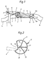
- FIG. 1 shows a door actuation mechanism which is damped according to the invention.
- An outer door handle not shown in more detail, which is pivotably mounted at one end, engages at the other end via the extension (17) through the door wall and is at the end (4) of the extension (17) a lever (5) articulated.
- the lever (5) is rotatably supported by the axis (2) and has an extension (6) which is fixedly connected to it and serves as a mass balance weight.
- the axis (2) like another axis (10), is mounted vertically on two parallel, horizontally running retaining plates, between which the lever (5) is located, only the lower retaining plate (1) being shown in the section of the drawing .
- the lever (5) After operating the outer door handle, the lever (5) is in a position rotated counter to the direction of the arrow shown. After releasing the outer door handle, the spring (7) a return movement in the direction of the arrow shown via the lever (5). This takes place initially without the action of the damping element (11), the locking mechanism (not shown here) coupled to the outside door handle via the rod (16) being actuated in this movement phase. Before the lever (5) reaches its end position shown, the extension (6) engages in a recess (14) in the damping element (11) and carries it in a rotational movement about the axis (10).
- the damping element (11) exerts a force, which is dependent on its angular velocity, on the extension (6), which brakes the rotary movement of the lever (5) caused by the spring (7).
- the system reaches its end position at low speed with a relatively long braking distance compared to elastic damping pads, which enables effective noise reduction.
- the damping element (11) is reset again via the extension (6) which engages in the recess (14). This also prevents jerky lever actuation that is damaging to the material.
- the damping element (11) can be designed as shown in FIG. 2. It consists of a cylinder-like sleeve that has a bottom and a cover and is rotatably mounted on the shaft (10) that is passed through. A recess (14) is arranged in the circular cylindrical outer wall (22). The externally sealed cavity (20) inside the sleeve is filled with a liquid of suitable viscosity. Rectangular wing plates (18, 19, 23), which are designed as perforated plates, are attached to the fixed axis (10) in the cavity (20). A corresponding wing plate (21) is firmly connected to the outer wall (22). When the outer wall rotates (22) relative to the fixed axis (10) the liquid must flow through the openings in the perforated plates. As is known, the resistance force exerted by the viscosity of the liquid increases with increasing relative speed. The damping element therefore exerts the desired speed-dependent damping force on the extension (6).
Landscapes
- Lock And Its Accessories (AREA)
- Fluid-Damping Devices (AREA)
Claims (8)
- Poignée de porte pour véhicules automobiles, qui possède un levier d'actionnement (5) pour actionner un dispositif de fermeture d'une porte de véhicule, dont le mouvement de retour à la position de départ se produit sous l'action de forces élastiques, et est limité par une butée (13a), cependant qu'il est prévu des moyens d'atténuation du bruit,
caractérisée
en ce qu'un de ces moyens est un élément amortisseur mobile (11) qui peut être accouplé au levier d'actionnement (5) au moins peu de temps avant l'arrivée à sa position de départ, et exerce sur lui une force dirigée en sens inverse de la force élastique, qui décroît avec la décroissance de la vitesse du levier d'actionnement (5), et reste plus grande que la force élastique jusque peu de temps avant l'arrivée à la position de départ, l'élément amortisseur (11) produisant la force de ralentissement fonction de la vitesse sous l'action d'un effet de viscosité. - Poignée de porte selon la revendication 1,
caractérisée
en ce que, sur un segment partiel de l'ensemble de la course de retour du levier d'actionnement (5), il n'y a pas de liaison entre l'élément amortisseur (11) et le levier d'actionnement (5). - Poignée de porte selon la revendication 1 ou 2,
caractérisée
en ce que l'élément amortisseur (11) est monté rotatif. - Poignée de porte selon la revendication 3,
caractérisée
en ce que l'élément amortisseur (11) est un cylindre creux (20) rempli de liquide et dans lequel sont disposées des palettes (18, 19, 21, 23) munies d'ouvertures de laminage. - Poignée de porte selon la revendication 3 ou 4,
caractérisée
en ce que l'élément amortisseur (11) présente, sur sa circonférence, une échancrure (14) dans laquelle s'engage le levier d'actionnement (5) ou un prolongement (6) solidaire de ce levier. - Poignée de porte selon la revendication 5,
caractérisée
en ce que le levier d'actionnement (5) ou le prolongement (6) s'engage dans l'échancrure (14) dans les deux sens de rotation de l'élément amortisseur (11). - Poignée de porte selon une ou plusieurs des revendications 1 à 6,
caractérisée
en ce que la butée (13a) de limitation du mouvement de retour attaque l'élément amortisseur (11). - Poignée de porte selon la revendication 7,
caractérisée
en ce que deux butées fixes (13a, 13b) limitent le mouvement de l'élément amortisseur (11) sur les deux côtés, par l'intermédiaire d'une protubérance (12) qui fait saillie sur cet élément.
Applications Claiming Priority (2)
| Application Number | Priority Date | Filing Date | Title |
|---|---|---|---|
| DE3931866A DE3931866C1 (fr) | 1989-09-23 | 1989-09-23 | |
| DE3931866 | 1989-09-23 |
Publications (2)
| Publication Number | Publication Date |
|---|---|
| EP0419809A1 EP0419809A1 (fr) | 1991-04-03 |
| EP0419809B1 true EP0419809B1 (fr) | 1993-06-09 |
Family
ID=6390091
Family Applications (1)
| Application Number | Title | Priority Date | Filing Date |
|---|---|---|---|
| EP90114655A Expired - Lifetime EP0419809B1 (fr) | 1989-09-23 | 1990-07-31 | Clenche pour véhicule |
Country Status (4)
| Country | Link |
|---|---|
| US (1) | US5092642A (fr) |
| EP (1) | EP0419809B1 (fr) |
| JP (1) | JPH0749743B2 (fr) |
| DE (1) | DE3931866C1 (fr) |
Families Citing this family (32)
| Publication number | Priority date | Publication date | Assignee | Title |
|---|---|---|---|---|
| DE4233037A1 (de) * | 1992-10-01 | 1994-04-14 | Daimler Benz Ag | Griff zum Öffnen eines beweglichen Karosserieteils eines Kraftfahrzeuges |
| FR2696775B1 (fr) * | 1992-10-09 | 1994-12-30 | Manducher Sa | Perfectionnements aux poignées de porte à palettes basculantes. |
| DE4303532C2 (de) * | 1993-02-06 | 2000-08-31 | Opel Adam Ag | Türschloß für eine Kraftfahrzeugtür |
| US5560659A (en) * | 1994-11-04 | 1996-10-01 | Adac Plastics, Inc. | Door handle assembly |
| DE19604940C2 (de) * | 1996-02-10 | 2002-04-18 | Schmidt Gmbh R | Vorrichtung zur Verlangsamung der Schwenk- oder Schiebebewegung von Kfz.-Teilen |
| DE19655100B4 (de) * | 1996-07-19 | 2007-12-20 | Kendrion Rsl Gmbh & Co. Kg | Dämpfungseinrichtung für einen Haltegriff in einem Kraftfahrzeug |
| US5743575A (en) * | 1997-01-27 | 1998-04-28 | Adac Plastics, Inc. | Fluid-damped automotive door latch actuator |
| US6042159A (en) * | 1997-08-01 | 2000-03-28 | Adac Plastics, Inc. | Door handle assembly |
| US6099052A (en) * | 1998-10-15 | 2000-08-08 | Adac Plastics, Inc. | Door handle assembly with inertial lock |
| US6234041B1 (en) * | 1999-08-23 | 2001-05-22 | Adac Plastics, Inc. | Combined cushion and seal for vehicular door handle assembly |
| US6367124B1 (en) | 1999-09-09 | 2002-04-09 | Illinois Tool Works Inc. | Damper and a door handle |
| US6565134B1 (en) | 2000-04-21 | 2003-05-20 | Adac Plastics, Inc. | Handle with side impact counterweight having installation position |
| US6575508B2 (en) | 2000-04-21 | 2003-06-10 | Adac Plastics, Inc. | Handle with unidirectional counterweight |
| US6572159B2 (en) * | 2000-05-03 | 2003-06-03 | Kiekert Ag | Damped actuating system for motor-vehicle door latch |
| DE10046726A1 (de) * | 2000-09-21 | 2002-04-11 | Bayerische Motoren Werke Ag | Türgriff, insbesondere an einem Kraftfahrzeug |
| DE10052640A1 (de) * | 2000-10-24 | 2002-05-02 | Bayerische Motoren Werke Ag | Türgriff mit Dämpfungseinrichtung, insbesondere an einer Kraftfahrzeugtür |
| DE10118658A1 (de) | 2001-04-14 | 2002-10-24 | Itw Automotive Prod Gmbh & Co | Türinnenbetätigung für Automobile |
| US6733049B2 (en) | 2002-07-03 | 2004-05-11 | The Boeing Company | Apparatus and methods for latching an aircraft door |
| DE10348942B4 (de) * | 2003-10-18 | 2005-10-06 | Daimlerchrysler Ag | Schließeinrichtung mit Geräuschoptimierung |
| CN1985063B (zh) * | 2004-07-09 | 2012-11-07 | 松下电器产业株式会社 | 门装置及冷藏库 |
| DE102004037983B3 (de) * | 2004-08-05 | 2006-01-12 | Huf Hülsbeck & Fürst Gmbh & Co. Kg | Vorrichtung zur Betätigung von Schlössern an Türen oder Klappen von Fahrzeugen |
| US20080197582A1 (en) * | 2007-02-19 | 2008-08-21 | Botten Eric M | Outer door handle gasket for automotive vehicles |
| IT1392678B1 (it) * | 2009-01-19 | 2012-03-16 | Valeo Spa | Dispositivo di sicurezza per maniglie di veicoli e maniglia di veicoli comprendente questo dispositivo di sicurezza |
| JP5460478B2 (ja) * | 2010-06-18 | 2014-04-02 | 株式会社パイオラックス | ロック装置 |
| US9062477B2 (en) * | 2012-11-28 | 2015-06-23 | Huf North America Automotive Parts Mfg. Corp. | Vehicular door handle assembly with inertial secondary catch position |
| DE102013106176A1 (de) * | 2013-06-13 | 2014-12-18 | Huf Hülsbeck & Fürst Gmbh & Co. Kg | Türgriffanordnung für ein Kraftfahrzeug |
| JP6066078B2 (ja) * | 2013-06-21 | 2017-01-25 | アイシン精機株式会社 | 車両のドアアウタハンドル構造 |
| KR101481352B1 (ko) * | 2013-12-19 | 2015-01-12 | 현대자동차주식회사 | 도어 아웃사이드핸들 |
| DE102014004550A1 (de) * | 2014-03-31 | 2015-10-01 | Kiekert Aktiengesellschaft | Betätigungseinrichtung für ein Kraftfahrzeugschloss |
| DE102015101630A1 (de) * | 2015-02-05 | 2016-08-11 | Dr. Ing. H.C. F. Porsche Aktiengesellschaft | Türgriffeinrichtung |
| JP6420703B2 (ja) * | 2015-03-30 | 2018-11-07 | アイシン精機株式会社 | 車両用ドアハンドル装置 |
| US10822841B2 (en) | 2016-08-24 | 2020-11-03 | Accurate Lock & Hardware Co. Llc | Door latch with delayed return mechanism |
Family Cites Families (11)
| Publication number | Priority date | Publication date | Assignee | Title |
|---|---|---|---|---|
| US1688472A (en) * | 1923-03-30 | 1928-10-23 | Sargent & Co | Latch |
| FR1091427A (fr) * | 1953-01-17 | 1955-04-12 | Daimler Benz Ag | Dispositif de verrouillage pour portières de véhicules |
| GB1159718A (en) * | 1966-11-22 | 1969-07-30 | Arnold Ratcliffe | Improvements in or relating to Window Mountings. |
| DE2658159C3 (de) * | 1976-12-22 | 1981-09-17 | Bayerische Motoren Werke AG, 8000 München | Türaußengriff für Kraftfahrzeuge |
| US4540208A (en) * | 1980-05-09 | 1985-09-10 | Reliable Security Systems, Inc. | Point-of-egress control device for safely securing emergency exit doors |
| JPS57174578A (en) * | 1981-04-21 | 1982-10-27 | Ohi Seisakusho Co Ltd | Handle apparatus of automobile door |
| DE3328667A1 (de) * | 1983-08-09 | 1985-02-21 | Bomoro Bocklenberg & Motte Gmbh & Co Kg, 5600 Wuppertal | Kraftfahrzeug-tuerschloss, -haubenschloss od. dgl. mit motorischer schliesshilfe |
| JPH0235107B2 (ja) * | 1983-08-29 | 1990-08-08 | Ooi Seisakusho Kk | Jidoshayodoahandorusochi |
| DE3403003C2 (de) * | 1984-01-28 | 1986-01-09 | Daimler-Benz Ag, 7000 Stuttgart | In einer Ruhestellung innerhalb einer Türebene liegender Türgriff, insbesondere für Kraftwagen |
| DE3728086A1 (de) * | 1987-08-22 | 1989-03-02 | Vdo Schindling | Schliesshilfe fuer eine fahrzeugtuer |
| GB2214556A (en) * | 1988-01-18 | 1989-09-06 | Von Duprin Inc | A panic exit device |
-
1989
- 1989-09-23 DE DE3931866A patent/DE3931866C1/de not_active Expired - Fee Related
-
1990
- 1990-07-31 EP EP90114655A patent/EP0419809B1/fr not_active Expired - Lifetime
- 1990-09-21 JP JP25040890A patent/JPH0749743B2/ja not_active Expired - Lifetime
- 1990-09-21 US US07/585,946 patent/US5092642A/en not_active Expired - Fee Related
Also Published As
| Publication number | Publication date |
|---|---|
| JPH0749743B2 (ja) | 1995-05-31 |
| EP0419809A1 (fr) | 1991-04-03 |
| DE3931866C1 (fr) | 1991-03-21 |
| JPH03122382A (ja) | 1991-05-24 |
| US5092642A (en) | 1992-03-03 |
Similar Documents
| Publication | Publication Date | Title |
|---|---|---|
| EP0419809B1 (fr) | Clenche pour véhicule | |
| DE10211294B4 (de) | Möbelbeschlag mit Brems-und Dämpfungsvorrichtung | |
| DE2513302C2 (de) | Blockierbare pneumatische oder hydropneumatische Feder | |
| DE4038720C2 (de) | Obertürschließer mit Gleitschienengestänge | |
| DE102010009375B4 (de) | Dämpfereinrichtung | |
| DE202004021727U1 (de) | Scharnier | |
| DE3825594C2 (fr) | ||
| EP3394371B1 (fr) | Dispositif de sécurité pour un véhicule à moteur comprenant un pêne pivotant et une position de préverrouillage et une position de verrouillage principal | |
| EP3396088A1 (fr) | Poignée de porte pour véhicule | |
| EP2811090B1 (fr) | Agencement de poignée de porte pour un véhicule | |
| WO2012095084A1 (fr) | Dispositif d'actionnement pour porte de véhicule | |
| DE102017216920A1 (de) | Türgriffeinrichtung für eine Tür eines Kraftfahrzeugs, Tür, Kraftfahrzeug | |
| DE19825708A1 (de) | Crashsicheres Fahrzeugtürschloß | |
| EP3728770B1 (fr) | Dispositif de poignée de porte d'un véhicule automobile | |
| WO2008009383A1 (fr) | Frein à disque, notamment destiné à des véhicules utilitaires, cylindre d'actionnement d'un frein à disque | |
| EP1694932B1 (fr) | Poignee exterieure de portiere et procede de blocage automatique du mouvement pivotant d'une poignee exterieure de portiere en cas de choc lateral | |
| WO2003018940A1 (fr) | Servo-porte-serrure pour serrure de porte, en particulier serrure de porte de vehicule automobile | |
| DE4000865A1 (de) | Gasfeder mit zwischenarretierung | |
| EP1017918B1 (fr) | Fermeture en forme de barre, presentant une course d'actionnement s'eloignant du vantail de porte | |
| DD269588A5 (de) | Teleskoparm, insbesondere fuer ueber schwenkarme betaetigte, durch kippen sich mit der fahrzeugkarosserie verriegelnde aussenschwenktueren von fahrzeugen | |
| DE3825593C1 (en) | Lock for doors or flaps of motor vehicles | |
| EP3803006B1 (fr) | Ensemble poignée de porte conçu pour un véhicule automobile | |
| EP2511463B1 (fr) | Fenêtre, porte ou analogue pourvue d'un dispositif d'amortissement | |
| DE19605586A1 (de) | Vorrichtung zur Schließfolgesteuerung für zweiflügelige Türen, insbesondere für Feuerschutztüren | |
| DE2924551A1 (de) | Tuerkonstruktion fuer fahrzeuge, bestehend aus einer ein- oder zweifluegeligen tuer |
Legal Events
| Date | Code | Title | Description |
|---|---|---|---|
| PUAI | Public reference made under article 153(3) epc to a published international application that has entered the european phase |
Free format text: ORIGINAL CODE: 0009012 |
|
| 17P | Request for examination filed |
Effective date: 19910110 |
|
| AK | Designated contracting states |
Kind code of ref document: A1 Designated state(s): FR GB IT SE |
|
| 17Q | First examination report despatched |
Effective date: 19920626 |
|
| ITF | It: translation for a ep patent filed |
Owner name: BARZANO' E ZANARDO ROMA S.P.A. |
|
| GRAA | (expected) grant |
Free format text: ORIGINAL CODE: 0009210 |
|
| AK | Designated contracting states |
Kind code of ref document: B1 Designated state(s): FR GB IT SE |
|
| GBT | Gb: translation of ep patent filed (gb section 77(6)(a)/1977) |
Effective date: 19930624 |
|
| ET | Fr: translation filed | ||
| PLBE | No opposition filed within time limit |
Free format text: ORIGINAL CODE: 0009261 |
|
| STAA | Information on the status of an ep patent application or granted ep patent |
Free format text: STATUS: NO OPPOSITION FILED WITHIN TIME LIMIT |
|
| 26N | No opposition filed | ||
| EAL | Se: european patent in force in sweden |
Ref document number: 90114655.5 |
|
| PGFP | Annual fee paid to national office [announced via postgrant information from national office to epo] |
Ref country code: FR Payment date: 19960716 Year of fee payment: 7 |
|
| PGFP | Annual fee paid to national office [announced via postgrant information from national office to epo] |
Ref country code: SE Payment date: 19960719 Year of fee payment: 7 |
|
| PGFP | Annual fee paid to national office [announced via postgrant information from national office to epo] |
Ref country code: GB Payment date: 19960722 Year of fee payment: 7 |
|
| PG25 | Lapsed in a contracting state [announced via postgrant information from national office to epo] |
Ref country code: GB Free format text: LAPSE BECAUSE OF NON-PAYMENT OF DUE FEES Effective date: 19970731 |
|
| PG25 | Lapsed in a contracting state [announced via postgrant information from national office to epo] |
Ref country code: SE Free format text: LAPSE BECAUSE OF NON-PAYMENT OF DUE FEES Effective date: 19970801 |
|
| REG | Reference to a national code |
Ref country code: GB Ref legal event code: 732E |
|
| REG | Reference to a national code |
Ref country code: FR Ref legal event code: TP |
|
| GBPC | Gb: european patent ceased through non-payment of renewal fee |
Effective date: 19970731 |
|
| PG25 | Lapsed in a contracting state [announced via postgrant information from national office to epo] |
Ref country code: FR Free format text: LAPSE BECAUSE OF NON-PAYMENT OF DUE FEES Effective date: 19980331 |
|
| EUG | Se: european patent has lapsed |
Ref document number: 90114655.5 |
|
| REG | Reference to a national code |
Ref country code: FR Ref legal event code: ST |
|
| PG25 | Lapsed in a contracting state [announced via postgrant information from national office to epo] |
Ref country code: IT Free format text: LAPSE BECAUSE OF NON-PAYMENT OF DUE FEES;WARNING: LAPSES OF ITALIAN PATENTS WITH EFFECTIVE DATE BEFORE 2007 MAY HAVE OCCURRED AT ANY TIME BEFORE 2007. THE CORRECT EFFECTIVE DATE MAY BE DIFFERENT FROM THE ONE RECORDED. Effective date: 20050731 |