EP0419406B1 - Destillationsanlage zur Herstellung von Wasserstoff-Peroxid - Google Patents
Destillationsanlage zur Herstellung von Wasserstoff-Peroxid Download PDFInfo
- Publication number
- EP0419406B1 EP0419406B1 EP90810677A EP90810677A EP0419406B1 EP 0419406 B1 EP0419406 B1 EP 0419406B1 EP 90810677 A EP90810677 A EP 90810677A EP 90810677 A EP90810677 A EP 90810677A EP 0419406 B1 EP0419406 B1 EP 0419406B1
- Authority
- EP
- European Patent Office
- Prior art keywords
- distillation column
- distillation
- components
- evaporator
- plant according
- Prior art date
- Legal status (The legal status is an assumption and is not a legal conclusion. Google has not performed a legal analysis and makes no representation as to the accuracy of the status listed.)
- Expired - Lifetime
Links
Images


Classifications
-
- C—CHEMISTRY; METALLURGY
- C01—INORGANIC CHEMISTRY
- C01B—NON-METALLIC ELEMENTS; COMPOUNDS THEREOF; METALLOIDS OR COMPOUNDS THEREOF NOT COVERED BY SUBCLASS C01C
- C01B15/00—Peroxides; Peroxyhydrates; Peroxyacids or salts thereof; Superoxides; Ozonides
- C01B15/01—Hydrogen peroxide
- C01B15/013—Separation; Purification; Concentration
-
- B—PERFORMING OPERATIONS; TRANSPORTING
- B01—PHYSICAL OR CHEMICAL PROCESSES OR APPARATUS IN GENERAL
- B01D—SEPARATION
- B01D3/00—Distillation or related exchange processes in which liquids are contacted with gaseous media, e.g. stripping
- B01D3/14—Fractional distillation or use of a fractionation or rectification column
-
- Y—GENERAL TAGGING OF NEW TECHNOLOGICAL DEVELOPMENTS; GENERAL TAGGING OF CROSS-SECTIONAL TECHNOLOGIES SPANNING OVER SEVERAL SECTIONS OF THE IPC; TECHNICAL SUBJECTS COVERED BY FORMER USPC CROSS-REFERENCE ART COLLECTIONS [XRACs] AND DIGESTS
- Y02—TECHNOLOGIES OR APPLICATIONS FOR MITIGATION OR ADAPTATION AGAINST CLIMATE CHANGE
- Y02P—CLIMATE CHANGE MITIGATION TECHNOLOGIES IN THE PRODUCTION OR PROCESSING OF GOODS
- Y02P20/00—Technologies relating to chemical industry
- Y02P20/10—Process efficiency
- Y02P20/129—Energy recovery, e.g. by cogeneration, H2recovery or pressure recovery turbines
-
- Y—GENERAL TAGGING OF NEW TECHNOLOGICAL DEVELOPMENTS; GENERAL TAGGING OF CROSS-SECTIONAL TECHNOLOGIES SPANNING OVER SEVERAL SECTIONS OF THE IPC; TECHNICAL SUBJECTS COVERED BY FORMER USPC CROSS-REFERENCE ART COLLECTIONS [XRACs] AND DIGESTS
- Y10—TECHNICAL SUBJECTS COVERED BY FORMER USPC
- Y10S—TECHNICAL SUBJECTS COVERED BY FORMER USPC CROSS-REFERENCE ART COLLECTIONS [XRACs] AND DIGESTS
- Y10S203/00—Distillation: processes, separatory
- Y10S203/04—Heat pump
Definitions
- the invention relates to a distillation plant for the production of concentrated hydrogen peroxide (H2O2) with an evaporator, a liquid separator and a distillation column as components and a packing for the distillation column of the plant.
- H2O2 concentrated hydrogen peroxide
- the object of the invention is to overcome these disadvantages and to create a system with significantly reduced pressure drop and lower operating and maximum temperatures and thus the greatest possible safety of the system.
- the product content of the system, the investment and the space requirement should also be reduced.
- a compressor can be used as the heat pump instead of the condenser, whereby particularly low operating costs can be achieved.
- a riser tube evaporator, a lamella liquid separator, and / or a mixing condenser with a complete counterflow principle can be used as components with a particularly low pressure drop. Very good results are achieved with an arrangement according to the invention in which the total pressure drop is less than 20 mbar.
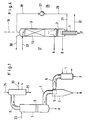
- a previous peroxide distillation plant according to FIG. 1 has a feed F (inlet) and two product outlets A and B, the pure peroxide solution being obtained at product outlet A.
- F 35%
- A 43% pure
- B 53% H2O2.
- the system has the individual components: evaporator 1, separator 2, distillation column 3 and condenser 4, which are connected by the bent connecting lines 6, 7, 8.
- This known system has relatively high pressure drops, firstly due to the bends and cross-sectional reductions in the connecting lines 6, 7, 8 and also in the components, for example in a cyclone 5 as a separator 2 and in the distillation column with trays 9
- Return 23 and to the condenser 4 a vacuum connection 30 and a cooling water inlet and outlet 24, 25 are connected.
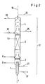
- FIGS. 2 and 3 show, schematically or in more detail, a peroxide distillation plant according to the invention, the components 1 to 4 being column-like, in direct succession are arranged in a vertical axis 16 and combined to form a structural unit 17.
- the evaporator 1 is directly connected to the separator 2 and this is built as an extension of the distillation column 3.
- the condenser 4 is placed on the distillation column 3.
- a riser evaporator 11 with a steam feed line 21 and a condensate drain 22, a lamellar liquid separator 12, a mixing condenser 14 with a complete counterflow principle and, above all, an ordered column packing 13 with a large surface area, for example a Sulzer packing, are used here as components with low flow resistance or pressure drop.
- the assembly 17 can consist of two parts which are joined together by means of only one flange 18. In this way, the tightness problems of previous, multi-assembled systems (FIG. 1) can also be overcome.
- the system can also be designed without a flange 18 as a one-piece, welded structural unit 17, for example with a manhole 33 for inspections.
- the system is preferably made entirely of pure aluminum or of stainless steel.
- the passage cross section 34 in the lower part of the column 3 can also be enlarged with a simultaneous widening 35 of the column wall.
- FIG. 4 shows a distillation plant according to the invention in which a heat pump 26 is used instead of the condenser 4.
- This consists of a compressor 27, for example as a one- or two-stage radial compressor, which is connected via lines 28, 29 to column 3 and evaporator 1 and which compresses the vapors of the column top to an increased (P, T) value to such an extent that this is sufficient to heat the evaporator 1.
- a heat pump of this type Only thanks to the design of the system according to the invention very low pressure drop, it is economically possible and sensible to use a heat pump of this type. With such a system according to FIG. 4, however, the operating costs can again be significantly reduced.
- FIG. 5 shows on the basis of a (P, T) diagram the improvement which can be achieved with systems (20) according to the invention compared to previous systems (10).
- 31 represents the vapor pressure curve of water and 32 the vapor pressure curve of an H2O2 solution.
- the point (P1, T1) with the pressure P1 and the temperature T1 indicates the top values in the condenser (or the distillation column for FIG. 4).
- P and T rise along the system according to arrows 10 for previous systems and 20 for systems according to the invention.
- the relatively high maximum values of previous systems are designated with (P2, T2).
- P3, P3) are generated with distillation plants according to the invention.
- the large pressure drop DP2 of a previous system is thus reduced to only a fraction corresponding to DP3 with systems according to the invention.
- the resulting reduction in temperature DT as well as the pressure drop DP mean corresponding massive improvements in plant safety and economy.
Description
- Die Erfindung betrifft eine Destillationsanlage zur Herstellung von konzentriertem Wasserstoff-Peroxid (H₂O₂) mit einem Verdampfer, einem Flüssigkeitsabscheider und einer Destillationskolonne als Komponenten und eine Packung für die Destillationskolonne der Anlage.
- Bei solchen bekannten Peroxidanlagen sind die einzelnen Komponenten mittels gebogener Rohre miteinander verbunden. Dabei tritt jedoch ein relativ hoher Druckabfall über die ganze Anlage auf, was wiederum notwendigerweise einen entsprechend grossen Temperaturanstieg in der Anlage bis zum Verdampfer bedingt. Vor allem aus Sicherheitsgründen sind bei der Peroxidproduktion jedoch unbedingt möglichst tiefe Temperaturen einzuhalten. Bisherige Anlagen sind überdies aufwendig gebaut und erfordern auch viel Bauraum und Gebäudeaufwand für die Schutzumhüllung. Auch deren Produktinhalt ist noch unerwünscht gross.
- Aufgabe der Erfindung ist es, diese Nachteile zu überwinden und eine Anlage zu schaffen mit wesentlich reduziertem Druckabfall und tieferen Betriebs- und Maximaltemperaturen und damit grösstmöglicher Sicherheit der Anlage. Ueberdies sollen auch der Produktinhalt der Anlage, der Investitionsaufwand und der Raumbedarf reduziert werden.
- Diese Aufgabe wird erfindungsgemäss gelöst durch die Anlage nach Anspruch 1 und die Packung nach Anspruch 8. Durch die kompakte Bauweise in einer Achse ohne Verbindungsleitungen, Umlenkungen und Querschnittsverengungen und durch die minimalen Druckabfall aufweisenden Komponenten, vor allem auch in der geordneten Packung der Destillationskolonne, werden ein sehr geringer totaler Druckabfall und damit tiefe Betriebstemperaturen bei wesentlich geringeren Investitionskosten und Platzbedarf erreicht. Durch die kompakte Bauweise und den geringen Druckabfall wird wiederum auch der Produktinhalt reduziert und damit insgesamt die Sicherheit und die Wirtschaftlichkeit wesentlich erhöht. Die abhängigen Ansprüche betreffen vorteilhafte Weiterbildungen der Erfindung. Bei einer besonders vorteilhaften Ausführung ist auch ein Kondensator als weitere Komponente auf die Destillationskolonne aufgesetzt und in die Baueinheit integriert. In einer weiteren Ausführung kann anstelle des Kondensators ein Verdichter als Wärmepumpe eingesetzt sein, womit besonders niedrige Betriebskosten erreicht werden können. Als Komponenten mit besonders geringem Druckabfall können ein Steigrohrverdampfer, ein Lamellen-Flüssigkeitsabscheider, und/oder ein Mischkondensator mit vollständigem Gegenstromprinzip eingesetzt werden. Sehr gute Resultate werden mit einer erfindungsgemässen Anordnung erreicht, bei welcher der totale Druckabfall weniger als 20 mbar beträgt.
- Im folgenden wird die Erfindung anhand von Beispielen im Zusammenhang mit den Figuren näher erläutert. Es zeigen:
- Fig. 1
- eine bisherige Anlage mit separaten Komponenten;
- Fig. 2
- eine erfindungsgemässe Destillationsanlage schematisch;
- Fig. 3
- eine weitere erfindungsgemässe Anlage mit Kondensator;
- Fig. 4
- eine Anlage mit Wärmepumpe;
- Fig. 5
- das Funktionsprinzip einer erfindungsgemässen Destillationsanlage in einem (P, T)-Diagramm.
- Eine bisherige Peroxid-Destillationsanlage nach Fig. 1 weist eine Einspeisung F (Zulauf) und zwei Produktausgänge A und B auf, wobei beim Produktausgang A die reine Peroxidlösung anfällt. Beispielsweise kann F = 35 %, A = 43 % rein und B = 53 % H₂O₂ betragen. Die Anlage weist die einzelnen Komponenten: Verdampfer 1, Abscheider 2, Destillationskolonne 3 und Kondensator 4 auf, welche durch die gebogenen Verbindungsleitungen 6, 7, 8 verbunden sind. Diese bekannte Anlage weist relativ hohe Druckabfälle auf, einmal durch die Biegungen und Querschnittsverringerungen der Verbindungsleitungen 6, 7, 8 wie auch in den Komponenten, so in einem Zyklon 5 als Abscheider 2 und in der Destillationskolonne mit Böden 9. In die Kolonne 3 führt der Rücklauf 23 und an den Kondensator 4 sind ein Vakuumanschluss 30 sowie eine Kühlwasserzu- und -ableitung 24, 25 angeschlossen.
- Die Figuren 2 und 3 zeigen-schematisch bzw. detaillierter eine erfindungsgemässe Peroxid-Destillationsanlage, wobei die Komponenten 1 bis 4 kolonnenartig, direkt aufeinanderfolgend in einer vertikalen Achse 16 angeordnet und zu einer Baueinheit 17 zusammengefasst sind. Der Verdampfer 1 ist direkt an den Abscheider 2 und dieser als Verlängerung der Destillationskolonne 3 gebaut. Der Kondensator 4 ist auf die Destillationskolonne 3 aufgesetzt. Als Komponenten mit geringem Strömungswiderstand bzw. Druckabfall sind hier ein Steigrohrverdampfer 11 mit einer Dampfzuleitung 21 und einer Kondensatableitung 22, ein Lamellen-Flüssigkeitsabscheider 12, ein Mischkondensator 14 mit vollständigem Gegenstromprinzip und vor allem eine geordnete Kolonnenpackung 13 mit grosser Oberfläche eingesetzt, z.B. eine Sulzerpackung, Mellapak® usw. Zur einfachen Montage kann die Baueinheit 17 aus zwei Teilen bestehen, welche mittels nur eines Flanschs 18 zusammengefügt werden. Damit können auch die Dichtigkeitsprobleme bisheriger, mehrfach zusammengesetzter Anlagen (Fig. 1) überwunden werden. Die Anlage kann aber auch ohne Flansch 18 als einteilige, verschweisste Baueinheit 17 ausgeführt werden, beispielsweise mit einem Mannloch 33 für Inspektionen. Vorzugsweise ist die Anlage entweder ganz aus Reinaluminium oder aus rostfreiem Stahl gefertigt. Zur Erhöhung des Durchflusses in der Anlage kann z.B. der Durchgangsquerschnitt 34 im unteren Teil der Kolonne 3 auch vergrössert werden bei gleichzeitiger Verbreiterung 35 der Kolonnenwand.
- Fig. 4 zeigt eine erfindungsgemässe Destillationsanlage bei der anstelle des Kondensators 4 eine Wärmepumpe 26 eingesetzt ist. Diese besteht aus einem Verdichter 27, z.B. als ein- oder zweistufiger Radialverdichter, welcher über die Leitungen 28, 29 mit Kolonne 3 und Verdampfer 1 verbunden ist und welcher die Brüden des Kolonnenkopfs soweit auf einen erhöhten (P, T)-Wert verdichtet, dass dieser zur Beheizung des Verdampfers 1 ausreicht. Nur dank der erfindungsgemässen Konzeption der Anlage mit sehr geringem Druckabfall ist es wirtschaftlich überhaupt möglich und sinnvoll, eine Wärmepumpe in dieser Art einzusetzen. Mit einer solchen Anlage gemäss Fig. 4 können jedoch die Betriebskosten nochmals deutlich gesenkt werden.
- Fig. 5 zeigt anhand eines (P, T)-Diagramms die Verbesserung, welche mit erfindungsgemässen Anlagen (20) gegenüber bisherigen Anlagen (10) erreicht werden kann. 31 stellt die Dampfdruckkurve von Wasser und 32 die Dampfdruckkurve einer H₂O₂-Lösung dar. Der Punkt (P1, T1) mit dem Druck P1 und der Temperatur T1 gibt dabei die Kopfwerte im Kondensator (bzw. der Destillationskolonne für Fig. 4) an. P und T steigen entlang der Anlage gemäss den Pfeilen 10 für bisherige bzw. 20 für erfindungsgemässe Anlagen. Die relativ hohen Maximalwerte von bisherigen Anlagen sind mit (P2, T2) bezeichnet. Demgegenüber werden mit erfindungsgemässen Destillationsanlagen nur die erheblich kleineren Maximalwerte (P3, P3) erzeugt. Damit wird der grosse Druckabfall DP2 einer bisherigen Anlage auf nur einen Bruchteil entsprechend DP3 mit erfindungsgemässen Anlagen reduziert. Die resultierende Reduktion DT der Temperatur wie auch des Druckabfalls DP bedeuten entsprechend massive Verbesserungen der Anlagensicherheit und der Wirtschaftlichkeit. Ausgehend von Kopfwerten P1 = 60 mbar und T1 = 36° betragen die Werte für bisherige Anlagen beispielsweise: T2 = 60°C, P2 = 120 mbar mit einer Druckdifferenz DP2 von 60 mbar.
- Mit neuen Anlagen werden beispielsweise folgende Werte erreicht: P3 = 72 mbar, T3 = 50°C und damit einer Druckdifferenz DP3 von 12 mbar. Die erfindungsgemässe Reduktion des Druckabfalls DP beträgt hier also 48 mbar und die Temperaturreduktion DT = 10°C.
-


Claims (8)
- Destillationsanlage zur Herstellung von konzentriertem Wasserstoff-Peroxid (H₂O₂) mit einem Verdampfer (1), einem Flüssigkeitsabscheider (2) und einer Destillationskolonne (3) als Komponenten, dadurch gekennzeichnet, dass die Komponenten (1, 2, 3) in einer vertikalen Achse (16) nacheinander angeordnet und zu einer Baueinheit (17) zusammengefasst sind ohne Verbindungsleitungen zwischen den Elementen (1, 2, 3), wobei der Verdampfer (1) direkt an den Abscheider (2) und der Abscheider (2) als Verlängerung der Destillationskolonne (3) gebaut sind, dass alle Komponenten einen geringen Druckabfall aufweisen und dass die Destillationskolonne (3) eine geordnete Packung (13) aufweist.
- Destillationsanlage nach Anspruch 1, gekennzeichnet durch einen Kondensator (4) als weitere Komponente, welcher direkt auf der Destillationskolonne (3) aufgesetzt und damit in die Baueinheit (17) integriert ist.
- Destillationskolonne nach Anspruch 1, gekennzeichnet durch eine Wärmepumpe (26) in Form eines Verdichters (27), welcher über Leitungen (28, 29) mit dem Kopf der Destillationskolonne (3) und dem Verdampfer (1) verbunden ist.
- Destillationskolonne nach Anspruch 2, gekennzeichnet durch einen Mischkondensator (14) mit vollständigem Gegenstromprinzip.
- Destillationsanlage nach Anspruch 1, gekennzeichnet durch einen Steigrohrverdampfer (11).
- Destillationsanlage nach Anspruch 1, gekennzeichnet durch einen Lamellen-Flüssigkeitsabscheider (12).
- Destillationsanlage nach Anspruch 1, dadurch gekennzeichnet, dass der totale Druckabfall (DP3) der Komponenten weniger als 20 mbar beträgt.
- Verwendung einer geordneten Packung für die Destillationskolonne (3) einer Destillationsanlage nach einem der Ansprüche 1 bis 7.
Applications Claiming Priority (2)
| Application Number | Priority Date | Filing Date | Title |
|---|---|---|---|
| CH3462/89 | 1989-09-22 | ||
| CH346289 | 1989-09-22 |
Publications (2)
| Publication Number | Publication Date |
|---|---|
| EP0419406A1 EP0419406A1 (de) | 1991-03-27 |
| EP0419406B1 true EP0419406B1 (de) | 1993-10-20 |
Family
ID=4256466
Family Applications (1)
| Application Number | Title | Priority Date | Filing Date |
|---|---|---|---|
| EP90810677A Expired - Lifetime EP0419406B1 (de) | 1989-09-22 | 1990-09-06 | Destillationsanlage zur Herstellung von Wasserstoff-Peroxid |
Country Status (5)
| Country | Link |
|---|---|
| US (1) | US5171407A (de) |
| EP (1) | EP0419406B1 (de) |
| JP (1) | JP2938952B2 (de) |
| DE (1) | DE59003144D1 (de) |
| FI (1) | FI94218C (de) |
Cited By (1)
| Publication number | Priority date | Publication date | Assignee | Title |
|---|---|---|---|---|
| CN110860099A (zh) * | 2019-11-14 | 2020-03-06 | 聊城市鲁西化工工程设计有限责任公司 | 一种多品质双氧水提浓装置及其工艺和应用 |
Families Citing this family (16)
| Publication number | Priority date | Publication date | Assignee | Title |
|---|---|---|---|---|
| BE1005198A3 (fr) * | 1991-08-27 | 1993-05-25 | Solvay Interox | Procede pour l'obtention de solutions aqueuses epurees de peroxyde d'hydrogene. |
| WO1995004702A1 (en) * | 1993-08-11 | 1995-02-16 | Conoco Specialty Products Inc. | Peroxide treatment process |
| JP3328854B2 (ja) * | 1993-09-13 | 2002-09-30 | 三菱瓦斯化学株式会社 | 過酸化水素の濃縮精製方法 |
| ES2194965T3 (es) * | 1996-10-09 | 2003-12-01 | Sulzer Chemtech Ag | Instalacion de destilacion. |
| NL1013682C2 (nl) * | 1999-11-26 | 2001-05-30 | Purac Biochem Bv | Werkwijze en inrichting voor het zuiveren van een waterige oplossing van melkzuur. |
| DE10144013A1 (de) * | 2001-09-07 | 2003-03-27 | Basf Ag | Verfahren zur Aufarbeitung einer wässrigen Wasserstoffperoxid-Lösung aus einer Direktsynthese |
| ITBO20070104A1 (it) * | 2007-02-21 | 2008-08-22 | Kdvsistemi Brevetti S R L | Apparato per la produzione di combustibile sintetico |
| DE102010039748A1 (de) * | 2010-08-25 | 2012-03-01 | Evonik Degussa Gmbh | Verfahren zum Konzentrieren von wässriger Wasserstoffperoxidlösung |
| BR112015012879A2 (pt) * | 2012-12-10 | 2017-07-11 | Sulzer Chemtech Ag | evaporador e processo para uso do mesmo |
| PL403721A1 (pl) | 2013-04-30 | 2014-11-10 | Instytut Lotnictwa | Sposób otrzymywania nadtlenku wodoru, zwłaszcza klasy HTP do zastosowań napędowych i układ do destylacji próżniowej |
| PL233084B1 (pl) | 2015-07-14 | 2019-08-30 | Inst Lotnictwa | Jednostopniowy sposób otrzymywania nadtlenku wodoru klasy HTP ( High Test Peroxide) do zastosowań napędowych i układ do jego otrzymywania |
| KR102512609B1 (ko) | 2017-02-22 | 2023-03-21 | 미츠비시 가스 가가쿠 가부시키가이샤 | 정제 과산화수소 수용액의 제조 방법 및 제조 시스템 |
| CL2021001192A1 (es) | 2020-05-28 | 2021-11-19 | Evonik Operations Gmbh | Dispositivo y proceso para producir peróxido de hidrógeno mediante un proceso de antraquinona |
| EP4063355A1 (de) | 2021-03-22 | 2022-09-28 | Evonik Operations GmbH | Integriertes verfahren und anlage zur herstellung von styrol und propenoxid |
| AU2022274987A1 (en) | 2021-05-10 | 2023-12-21 | Evonik Operations Gmbh | Optimized steam network for the ao process |
| WO2022238145A1 (en) | 2021-05-10 | 2022-11-17 | Evonik Operations Gmbh | An integrated plant and an integrated process for making propene oxide |
Family Cites Families (19)
| Publication number | Priority date | Publication date | Assignee | Title |
|---|---|---|---|---|
| FR563908A (fr) * | 1922-06-29 | 1923-12-17 | Procédé et dispositifs pour la fabrication continue d'eau oxygénée (peroxyde d'hydrogène) de toute concentration voulue | |
| US2300985A (en) * | 1939-12-28 | 1942-11-03 | Sinclair Refining Co | Distillation |
| US2298064A (en) * | 1939-12-29 | 1942-10-06 | Mathieson Alkali Works Inc | Chemical manufacture |
| US2543001A (en) * | 1942-08-15 | 1951-02-27 | Foster Wheeler Corp | Continuous distillation and treatment of composite liquids |
| US2715607A (en) * | 1949-09-22 | 1955-08-16 | Lee Foundation For Nutritional | Knockdown distillation apparatus |
| NL94445C (de) * | 1952-04-24 | |||
| DE1025833B (de) * | 1952-12-19 | 1958-03-13 | Metallgesellschaft Ag | Verfahren zur Kondensation von Gemischen aus Wasserdampf und organischen Daempfen |
| US3073755A (en) * | 1959-08-11 | 1963-01-15 | Laporte Chemical | Concentration of hydrogen peroxide |
| DE1110143B (de) * | 1960-04-12 | 1961-07-06 | Kali Chemie Ag | Verfahren zum Konzentrieren verduennter waessriger Wasserstoffperoxydloesungen |
| DE1114168B (de) * | 1960-08-03 | 1961-09-28 | Bayer Ag | Destillationsvorrichtung mit Waermepumpe |
| DE1493688A1 (de) * | 1965-01-13 | 1969-06-19 | Bayer Ag | Verfahren und Vorrichtung zur Herstellung von 1,3,5-Trioxan hoechster Reinheit |
| US3445343A (en) * | 1967-02-01 | 1969-05-20 | Dmitry Mikhailovich Popov | Apparatus for evaporating-condensing separation of mixtures |
| AT274743B (de) * | 1967-09-28 | 1969-09-25 | Krems Chemie Gmbh | Verfahren und Vorrichtung zur kontinuierlichen Fraktionierung von Tallöl oder andern organischen Mehrstoffgemischen |
| US3755088A (en) * | 1969-08-04 | 1973-08-28 | Hydro Chem & Mineral Corp | Internally interconnected multi-stage distillation system |
| US3820582A (en) * | 1970-12-14 | 1974-06-28 | Rosenlew Ab Metallind O | Device for evaporation of liquids |
| US3961658A (en) * | 1972-07-07 | 1976-06-08 | Snam Progetti S.P.A. | Sea water desalination apparatus |
| US4575403A (en) * | 1982-06-04 | 1986-03-11 | Fmc Corporation | Apparatus for distilling phosphorus |
| SU1121018A1 (ru) * | 1983-05-19 | 1984-10-30 | Рижский Ордена Трудового Красного Знамени Политехнический Институт | Ректификационна установка |
| US4695349A (en) * | 1984-03-07 | 1987-09-22 | Linde Aktiengesellschaft | Process and apparatus for distillation and/or stripping |
-
1990
- 1990-08-21 US US07/570,209 patent/US5171407A/en not_active Expired - Lifetime
- 1990-08-23 FI FI904181A patent/FI94218C/fi active IP Right Grant
- 1990-09-06 EP EP90810677A patent/EP0419406B1/de not_active Expired - Lifetime
- 1990-09-06 DE DE90810677T patent/DE59003144D1/de not_active Expired - Fee Related
- 1990-09-19 JP JP2247641A patent/JP2938952B2/ja not_active Expired - Fee Related
Cited By (2)
| Publication number | Priority date | Publication date | Assignee | Title |
|---|---|---|---|---|
| CN110860099A (zh) * | 2019-11-14 | 2020-03-06 | 聊城市鲁西化工工程设计有限责任公司 | 一种多品质双氧水提浓装置及其工艺和应用 |
| CN110860099B (zh) * | 2019-11-14 | 2022-03-04 | 聊城市鲁西化工工程设计有限责任公司 | 一种多品质双氧水提浓装置及其工艺和应用 |
Also Published As
| Publication number | Publication date |
|---|---|
| DE59003144D1 (de) | 1993-11-25 |
| JP2938952B2 (ja) | 1999-08-25 |
| US5171407A (en) | 1992-12-15 |
| FI94218C (fi) | 1995-08-10 |
| FI94218B (fi) | 1995-04-28 |
| JPH03122005A (ja) | 1991-05-24 |
| FI904181A0 (fi) | 1990-08-23 |
| EP0419406A1 (de) | 1991-03-27 |
Similar Documents
| Publication | Publication Date | Title |
|---|---|---|
| EP0419406B1 (de) | Destillationsanlage zur Herstellung von Wasserstoff-Peroxid | |
| EP0229356B1 (de) | Mehrstufige Anordnung zur Gegenstromwaschung, deren Anwendung und zugehörige Verfahrensmassnahmen | |
| DE3302525A1 (de) | Destillationskolonne zur destillativen zerlegung eines aus mehreren fraktionen bestehenden zulaufproduktes | |
| WO2002055460A1 (de) | Verfahren und vorrichtung zur destillativen aufarbeitung von 1,6-hexandiol, 1,5-pentandiol und caprolacton | |
| WO1993019336A1 (de) | Verfahren zur tieftemperaturzerlegung von luft und luftzerlegungsanlage | |
| CH682982A5 (de) | Apparat zur Aufwärmung und Entgasung von Wasser. | |
| DE2441384A1 (de) | Zwangsumlaufverdampfer | |
| DE10207460C1 (de) | Kolonne zur Aufkonzentration von Phthalsäureanhydrid | |
| EP0781583A2 (de) | Verfahren und Apparateanordnung zur Aufwärmung und mehrstufigen Entgasung von Wasser | |
| DE3244521A1 (de) | Vorrichtung zum kontaktieren von gasen und fluessigkeiten | |
| DE1212231B (de) | System aus einem Siedewasser-Reaktor mit direkt angeschlossener Turbine und Verfahren zur Regelung eines derartigen Systems | |
| EP0243388B1 (de) | Anlage zur kontinuierlichen fettspaltung | |
| EP0174517B1 (de) | Anlage zum Desodorieren und/oder Entsäuern von Speiseölen, Fetten und Estern | |
| DE1170908B (de) | Kontaktturm fuer Gase und Fluessigkeiten | |
| DE3133803A1 (de) | Vorrichtung zum konzentrieren waessriger loesungen von glykol | |
| DE3236985C2 (de) | ||
| EP0425941A1 (de) | Apparat zur Entgasung und Aufwärmung von Wasser | |
| DE10005750C2 (de) | Kolonne zur Trennung von Gemischen, welche aus mindestens 3 unterschiedlichen Komponenten bestehen | |
| DE10135716A1 (de) | Verbesserter Fallfilmverdampfer zur Auftrennung von Stoffgemischen | |
| EP1249662B1 (de) | Dampferzeuger | |
| DE1667247A1 (de) | Vorrichtung zur gleichmaessigen Verteilung von Fluessigkeit auf eine Mehrzahl von Reaktionsrohren in einem Reaktor zur Durchfuehrung chemischer Reaktionen | |
| DE2358349A1 (de) | Zweistufiger niederdruckvorwaermer | |
| AT398428B (de) | Vorrichtung zum thermischen spalten eines gemisches mit flüssigen und gasförmigen kohlenwasserstoffen | |
| DE3837081C2 (de) | Verfahren zur Entnahme von Destillat genügend heißen Zustands in mehrstufigen Destillationsvorrichtungen | |
| DD201647A5 (de) | Vorrichtung zum konzentrieren waessriger loesungen von glykol |
Legal Events
| Date | Code | Title | Description |
|---|---|---|---|
| PUAI | Public reference made under article 153(3) epc to a published international application that has entered the european phase |
Free format text: ORIGINAL CODE: 0009012 |
|
| 17P | Request for examination filed |
Effective date: 19901112 |
|
| AK | Designated contracting states |
Kind code of ref document: A1 Designated state(s): CH DE FR IT LI SE |
|
| 17Q | First examination report despatched |
Effective date: 19930210 |
|
| GRAA | (expected) grant |
Free format text: ORIGINAL CODE: 0009210 |
|
| ITF | It: translation for a ep patent filed |
Owner name: ING. ZINI MARANESI & C. |
|
| AK | Designated contracting states |
Kind code of ref document: B1 Designated state(s): CH DE FR IT LI SE |
|
| RAP2 | Party data changed (patent owner data changed or rights of a patent transferred) |
Owner name: SULZER CHEMTECH AG |
|
| REF | Corresponds to: |
Ref document number: 59003144 Country of ref document: DE Date of ref document: 19931125 |
|
| ET | Fr: translation filed | ||
| PLBE | No opposition filed within time limit |
Free format text: ORIGINAL CODE: 0009261 |
|
| STAA | Information on the status of an ep patent application or granted ep patent |
Free format text: STATUS: NO OPPOSITION FILED WITHIN TIME LIMIT |
|
| 26N | No opposition filed | ||
| EAL | Se: european patent in force in sweden |
Ref document number: 90810677.6 |
|
| PGFP | Annual fee paid to national office [announced via postgrant information from national office to epo] |
Ref country code: CH Payment date: 20080915 Year of fee payment: 19 |
|
| PGFP | Annual fee paid to national office [announced via postgrant information from national office to epo] |
Ref country code: FR Payment date: 20080912 Year of fee payment: 19 Ref country code: IT Payment date: 20080925 Year of fee payment: 19 |
|
| PGFP | Annual fee paid to national office [announced via postgrant information from national office to epo] |
Ref country code: DE Payment date: 20080919 Year of fee payment: 19 |
|
| PGFP | Annual fee paid to national office [announced via postgrant information from national office to epo] |
Ref country code: SE Payment date: 20080912 Year of fee payment: 19 |
|
| REG | Reference to a national code |
Ref country code: CH Ref legal event code: PL |
|
| EUG | Se: european patent has lapsed | ||
| REG | Reference to a national code |
Ref country code: FR Ref legal event code: ST Effective date: 20100531 |
|
| PG25 | Lapsed in a contracting state [announced via postgrant information from national office to epo] |
Ref country code: DE Free format text: LAPSE BECAUSE OF NON-PAYMENT OF DUE FEES Effective date: 20100401 Ref country code: FR Free format text: LAPSE BECAUSE OF NON-PAYMENT OF DUE FEES Effective date: 20090930 |
|
| PG25 | Lapsed in a contracting state [announced via postgrant information from national office to epo] |
Ref country code: CH Free format text: LAPSE BECAUSE OF NON-PAYMENT OF DUE FEES Effective date: 20090930 Ref country code: LI Free format text: LAPSE BECAUSE OF NON-PAYMENT OF DUE FEES Effective date: 20090930 |
|
| PG25 | Lapsed in a contracting state [announced via postgrant information from national office to epo] |
Ref country code: IT Free format text: LAPSE BECAUSE OF NON-PAYMENT OF DUE FEES Effective date: 20090906 |
|
| PG25 | Lapsed in a contracting state [announced via postgrant information from national office to epo] |
Ref country code: SE Free format text: LAPSE BECAUSE OF NON-PAYMENT OF DUE FEES Effective date: 20090907 |