EP0418215A1 - Dispositif auxiliaire pour machine à coudre ou similaire pour déposer des pièces de travail - Google Patents
Dispositif auxiliaire pour machine à coudre ou similaire pour déposer des pièces de travail Download PDFInfo
- Publication number
- EP0418215A1 EP0418215A1 EP90890260A EP90890260A EP0418215A1 EP 0418215 A1 EP0418215 A1 EP 0418215A1 EP 90890260 A EP90890260 A EP 90890260A EP 90890260 A EP90890260 A EP 90890260A EP 0418215 A1 EP0418215 A1 EP 0418215A1
- Authority
- EP
- European Patent Office
- Prior art keywords
- workpiece
- additional device
- workpieces
- clamping
- holder
- Prior art date
- Legal status (The legal status is an assumption and is not a legal conclusion. Google has not performed a legal analysis and makes no representation as to the accuracy of the status listed.)
- Granted
Links
Images


Classifications
-
- D—TEXTILES; PAPER
- D05—SEWING; EMBROIDERING; TUFTING
- D05B—SEWING
- D05B41/00—Work-collecting devices
Definitions
- the invention relates to an additional device for sewing machines or the like.
- a workpiece shelf downstream of the machine table and preferably with a conveyor further conveying the workpieces in the feed direction over the table.
- the invention is therefore based on the object of eliminating these deficiencies and of creating an additional device of the type described at the outset, which allows the machined workpieces to be deposited automatically and thereby brings these workpieces together.
- the invention solves this problem in that a reciprocable from the machine table to the preferably designed as a compartment with a height-adjustable workpiece rest is provided, which has a cross finger to the direction of movement, cooperating in the area of the table end with a counterholder for clamping a part workpiece pushed out over the table end. If a workpiece is pushed so far towards the end of the table during or after machining that a desired workpiece part, e.g.
- the pickup is moved to the machine table in the clamping position, whereby the workpiece is clamped at the desired location between the clamping finger and the counterhold and another workpiece feed pushes the part of the workpiece still on the table over the clamping finger until it slips off the table and the workpiece hangs over the clamping finger.
- the customer only needs to be moved to the workpiece holder and the clamping finger (brings the workpiece for storage where it is placed on the floor or the existing stack of workpieces.
- a rocking of the pickup leads the clamping finger out of the workpiece and allows the next workpiece to be clamped and accepted.
- a part of the end face of the table end which can be provided with a corresponding support, advantageously serves directly as a counter-holder.
- the clamping finger is, according to the invention, mounted so that it can be extended and retracted, so that when the customer moves back the clamping finger no longer has to be moved out by the folded workpiece, but the workpiece is released by retracting the clamping finger. Before clamping a new workpiece, the clamping finger has to be extended again and works properly with the counter holder as a clamp.
- the customer carries a swivel arm forming a retaining clip on the side facing away from the counter-holder with the clamping finger, so that the workpiece is clamped during transfer from the table to the workpiece holder and does not hang loosely on the clamping finger.
- This swivel arm replaces a swiveling counter-holder, so that there are no space problems and the workpieces are always pushed directly from the table over the counter-holder and are not inserted between the counter-holder and the clamping finger in the hanging state must be clamped, which guarantees a trouble-free depositing process.
- a sliding plate which leads from the work surface of the table down into the clamping region of the counter-holder and clamping finger, which has blow-through openings and covers air cans aligned with the blow-through openings in the feed direction.
- a guide device is provided between the table and the tray for the workpieces brought by the customer to the tray, a correct, flat placement of the workpieces in the tray is ensured, since the workpiece parts hanging from the clamping finger can be raised and aligned in accordance with the guide device.
- a baffle that rises to the storage height and the workpieces are pulled up along, or a guide rod that runs transversely at the storage height and over which the workpieces are to be pulled is sufficient, but it is particularly advantageous if the guide device has a freely projecting guide finger arranged on the side of the machine table opposite the customer, which is pivotably mounted about a transverse axis to the direction of advance between the tray and the machine table.
- a guide finger can be used for workpieces with corresponding holes, for example when cutting underpants u.
- Swing into a corresponding hole in the clamped workpiece so that the workpiece folded over the clamping finger is then threaded with the hole on the finger. If the guide finger is then swiveled into the storage area, the workpiece is precisely and cleanly guided along the guide finger during the removal movement from the machine table to the storage area.
- the guide finger is curved in the direction of the rest, the guide properties of the guide finger are improved in a simple manner, and a corresponding lateral course of the curvature can also achieve an effect which spreads the workpiece during the guide movement of the workpiece along the guide finger.
- the guide finger is seated on a cross slide that can be moved transversely to the feed direction, the spreading and placement of the workpieces can be coordinated with the transfer from the machine table to the respective workpiece itself and a functionally reliable process can be ensured.
- the guide finger only needs to be moved after threading into the workpiece hole until the workpiece is clamped accordingly, so that after swiveling back in the storage direction, the workpiece is stretched out with the customer and spread out into the workpiece holder.
- the compartment of the workpiece holder is equipped with a pressure stamp which can be lowered from the top to the bottom, by means of which the workpieces placed in the holder can be flattened and stacked perfectly, which is further compounded by a corresponding interaction of the stamp and the customer. Return movement an additional help for the actual stacking of the workpieces in the tray can be achieved.
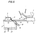
- an additional device 4 which has a longitudinal guide 6 between the machine table 2 provided alongside the work surface 5 of the work table 2 and the workpiece holder 3 has reciprocable 7.
- This pickup 7 consists of a longitudinal slide 8, on which a clamping finger 9, which can be moved in and out transversely to the feed direction, and a swivel arm 10, which can be swiveled in and out with the clamping finger 9, are mounted.
- the clamping finger 9 is assigned a counter-holder 11 in the end region of the machine table 2, so that a workpiece hanging from the table 2 can be clamped between the counter-holder 11 and the clamping finger 9 by appropriately moving the pickup 7 to the machine table 2.
- the machine table 2 is provided in its end region with a perforated slide plate 12 which leads from the table surface to the counter-holder 11 and covers air nozzles 13 which are directed in the feed direction of the workpiece through the blow-through openings 14 in the slide plate 12.
- air nozzles 13 which are directed in the feed direction of the workpiece through the blow-through openings 14 in the slide plate 12.
- a guide device 17 is provided below the pickup 7, which is intended to ensure a proper transfer of the workpieces from the machine table 2 into the holder 3 by the pickup 7.
- This guide device 17 consists of a guide plate 18 in the area of the customer side and of a freely projecting guide finger 19 on the opposite side of the machine table 2, which guide finger 19 is pivotable about a transverse axis to the feed direction on a cross slide 20 which can be displaced transversely to the feed direction and between workpiece storage 3 and machine table 2 can be pivoted back and forth.
- Guide plate 18 and guide finger 19 are curved toward the tray 3, so that the workpieces carried by the customer 7 to the tray 3 are raised at the end and placed flat in the tray.
- the workpiece holder 3 is designed as a compartment 21 which is open at the top and which has a height-adjustable bottom 22 for coordinating the compartment depth with the existing workpiece stack and is equipped with a plunger 23 which can be lowered from above onto such a workpiece stack to compress this stack.
- the sewing machine 1 or another processing machine can be designed and equipped in any suitable manner, a conveyor 24 conveying the machined workpieces in the feed direction advantageously being provided, which safely transports the workpieces into the area of the pickup 7 or, without manual intervention the counterhold 11 brings.
- Any devices can also be provided as drives for the individual movement sequences, but pneumatic cylinders 25, 26, 27, 28, 29, 30, 31 are particularly suitable for the actuating movements of longitudinal slides 8, clamping fingers 9, swivel arm 10, guide fingers 19 and its cross slide 20 as well as the shelf 22 and the pressure plunger 23, since this involves simple lifting movements of a certain size, which can be carried out with little effort and exactly by appropriately loading the pneumatic cylinders.
- the conveyor 24 ensures that the workpiece parts which have already been sewn are pushed further over the machine table 2 until they hang down over the slide plate 12 and the counter-holder 11 from the table.
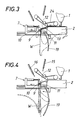
- the longitudinal slide 8 of the pick-up 7 is moved to the counter-holder 11 with the clamping finger 9 extended and the workpiece W clamped (FIG. 3) at the appropriate moment, for example in half the workpiece, without the Sewing process must be interrupted.
- Further sewing or further conveying of the workpiece W by the conveyor 24 also pushes the remaining workpiece part beyond the end of the table, so that the workpiece W turns over the clamping finger 9 and hangs together on the clamping finger.
- the swivel arm 10 closes and the workpiece is fixed by the holding clip formed from the clamping finger 9 and the swivel arm 10.
- the guide finger 19 pivots to the workpiece holder 3 and, in the case of a workpiece threaded onto the guide finger 19 with an opening, the cross slide 20 can move a corresponding distance to clamp the workpiece, so that this workpiece is spread between the clamping finger 19 and the holding clamp (Fig .4).
- the carriage 8 now only needs to travel up to the support 3, the workpiece being lifted by the guide finger 19 and the guide plate 18 with the parts hanging down during this carriage movement (FIG. 5), and the workpiece comes after removal to lie properly on the shelf 22 or an already existing workpiece stack by the guide finger.
- the shelf 22 must be brought into the appropriate position, depending on the stack height, so as not to impede the stacking of the workpieces.
- the workpiece is released by swiveling the swivel arm 10 and retracting the clamping finger 9 and the customer 7 can move back to the machine table 2 to take over the next workpiece W, whereupon the holding-down device 23 possibly compresses the stack in the storage 3. Since the workpiece storage over the pickup 7 is carried out independently of the machining process by the sewing machine 1, overlapping work is possible and the placement of the workpieces does not entail a delay in the workflow.
Landscapes
- Engineering & Computer Science (AREA)
- Textile Engineering (AREA)
- Sewing Machines And Sewing (AREA)
- Warehouses Or Storage Devices (AREA)
Applications Claiming Priority (2)
| Application Number | Priority Date | Filing Date | Title |
|---|---|---|---|
| AT215689A AT397971B (de) | 1989-09-15 | 1989-09-15 | Zusatzvorrichtung für nähmaschinen od. dgl. zum ablegen der bearbeiteten werkstücke |
| AT2156/89 | 1989-09-15 |
Publications (2)
| Publication Number | Publication Date |
|---|---|
| EP0418215A1 true EP0418215A1 (fr) | 1991-03-20 |
| EP0418215B1 EP0418215B1 (fr) | 1994-01-05 |
Family
ID=3528959
Family Applications (1)
| Application Number | Title | Priority Date | Filing Date |
|---|---|---|---|
| EP19900890260 Expired - Lifetime EP0418215B1 (fr) | 1989-09-15 | 1990-09-11 | Dispositif auxiliaire pour machine à coudre ou similaire pour déposer des pièces de travail |
Country Status (5)
| Country | Link |
|---|---|
| EP (1) | EP0418215B1 (fr) |
| JP (1) | JPH03170195A (fr) |
| AT (1) | AT397971B (fr) |
| DE (1) | DE59004114D1 (fr) |
| ES (1) | ES2047908T3 (fr) |
Citations (3)
| Publication number | Priority date | Publication date | Assignee | Title |
|---|---|---|---|---|
| FR2326525A1 (fr) * | 1975-10-02 | 1977-04-29 | Rockwell Rimoldi Spa | Dispositif d'empilage pour pieces vestimentaires dans une unite de couture |
| EP0201408A1 (fr) * | 1985-04-29 | 1986-12-17 | Eminence S.A. | Dispositif d'empilage de pièces textiles |
| DE8700117U1 (fr) * | 1987-01-03 | 1987-04-23 | Zawischka, Dieter, 7410 Reutlingen, De |
Family Cites Families (3)
| Publication number | Priority date | Publication date | Assignee | Title |
|---|---|---|---|---|
| DE2312878C3 (de) * | 1973-03-15 | 1980-05-22 | Duerkoppwerke Gmbh, 4800 Bielefeld | Mehrzweckgerät zur Aufnahme flexibler Arbeitsstücke |
| DE2627006C3 (de) * | 1976-06-16 | 1981-06-04 | Dürkoppwerke GmbH, 4800 Bielefeld | Vorrichtung zum flach ausgebreiteten Aufeinanderlegen großflächiger, flexibler Arbeitsstücke |
| DE2649471C2 (de) * | 1976-10-29 | 1978-12-21 | Pfaff Industriemaschinen Gmbh, 6750 Kaiserslautern | Vorrichtung zum Wegführen und Sammeln flexibler Werkstücke an einer Nähmaschine |
-
1989
- 1989-09-15 AT AT215689A patent/AT397971B/de not_active IP Right Cessation
-
1990
- 1990-09-11 EP EP19900890260 patent/EP0418215B1/fr not_active Expired - Lifetime
- 1990-09-11 DE DE90890260T patent/DE59004114D1/de not_active Expired - Fee Related
- 1990-09-11 ES ES90890260T patent/ES2047908T3/es not_active Expired - Lifetime
- 1990-09-14 JP JP24286790A patent/JPH03170195A/ja active Pending
Patent Citations (3)
| Publication number | Priority date | Publication date | Assignee | Title |
|---|---|---|---|---|
| FR2326525A1 (fr) * | 1975-10-02 | 1977-04-29 | Rockwell Rimoldi Spa | Dispositif d'empilage pour pieces vestimentaires dans une unite de couture |
| EP0201408A1 (fr) * | 1985-04-29 | 1986-12-17 | Eminence S.A. | Dispositif d'empilage de pièces textiles |
| DE8700117U1 (fr) * | 1987-01-03 | 1987-04-23 | Zawischka, Dieter, 7410 Reutlingen, De |
Also Published As
| Publication number | Publication date |
|---|---|
| EP0418215B1 (fr) | 1994-01-05 |
| AT397971B (de) | 1994-08-25 |
| JPH03170195A (ja) | 1991-07-23 |
| DE59004114D1 (de) | 1994-02-17 |
| ATA215689A (de) | 1993-12-15 |
| ES2047908T3 (es) | 1994-03-01 |
Similar Documents
| Publication | Publication Date | Title |
|---|---|---|
| EP0128487B2 (fr) | Machine-outil avec un magasin stationnaire | |
| CH684345A5 (de) | Verfahren und Vorrichtung zum Falten eines flachen, faltbaren Werkstücks. | |
| DE2924017A1 (de) | Vorrichtung zum anbringen elastischer ringe an schlauchfoermige kleidungsstuecke | |
| DE2456789C2 (de) | Nähautomat | |
| DE3709210C2 (fr) | ||
| EP0100420A1 (fr) | Appareil pour manipuler des pièces de travail | |
| DE3709251C2 (de) | Nähautomat | |
| DE4013066C2 (de) | Spulenwechselvorrichtung | |
| DE3709232C2 (fr) | ||
| DE3709264C2 (de) | Nähautomat | |
| DE3725265A1 (de) | Verfahren und vorrichtung zum wechseln von spinnkannen bei einer spinnereivorbereitungsmaschine | |
| DE3212629C2 (de) | Vorrichtung zum Falten von Bekleidung, insbesondere Kittel | |
| CH673831A5 (fr) | ||
| DE3823945C2 (fr) | ||
| DE1660822B2 (de) | Vorrichtung zum Formen eines ersten Werkstuckes und dessen Vernahen mit einem zweiten Werkstuck | |
| EP0418215B1 (fr) | Dispositif auxiliaire pour machine à coudre ou similaire pour déposer des pièces de travail | |
| DE4033177C2 (de) | Vorrichtung zum Zu- bzw. Überführen eines Nähgutkleinteiles | |
| EP0426886B1 (fr) | Procédé de fonctionnement et dispositif pour le transfert d'une part de bobines simples ou groupes de bobines d'un bobinoir, d'une assembleuse ou d'un métier à filer à un dispositif de transport de bobines et d'autre part de bobines vides du dispositif de transport au bobinoir, l'assembleuse ou le métier à filer | |
| DE2835994A1 (de) | Vorrichtung zum steuern einer kette von stichen bei einer naehmaschine | |
| DE19840749C2 (de) | Näheinheit zum Aufnähen von umzubuggenden oder vorgebuggten Taschen | |
| DE3010517C2 (de) | Falzmaschine mit einem Papieranleger | |
| DE2935895C2 (de) | Maschine zum Putzen und Trennen keramischer Formlinge | |
| DE19722610A1 (de) | Verfahren und Vorrichtung zum Falten und Stapeln von Nähgut | |
| EP1158083B1 (fr) | Dispositif de changement du fil supérieur | |
| DE3514466C1 (de) | Einrichtung zum Auslassen von Fellen |
Legal Events
| Date | Code | Title | Description |
|---|---|---|---|
| PUAI | Public reference made under article 153(3) epc to a published international application that has entered the european phase |
Free format text: ORIGINAL CODE: 0009012 |
|
| AK | Designated contracting states |
Kind code of ref document: A1 Designated state(s): CH DE ES FR GB GR IT LI |
|
| 17P | Request for examination filed |
Effective date: 19910902 |
|
| 17Q | First examination report despatched |
Effective date: 19930622 |
|
| GRAA | (expected) grant |
Free format text: ORIGINAL CODE: 0009210 |
|
| AK | Designated contracting states |
Kind code of ref document: B1 Designated state(s): CH DE ES FR GB GR IT LI |
|
| REF | Corresponds to: |
Ref document number: 59004114 Country of ref document: DE Date of ref document: 19940217 |
|
| REG | Reference to a national code |
Ref country code: ES Ref legal event code: FG2A Ref document number: 2047908 Country of ref document: ES Kind code of ref document: T3 |
|
| GBT | Gb: translation of ep patent filed (gb section 77(6)(a)/1977) |
Effective date: 19940131 |
|
| ET | Fr: translation filed | ||
| ITF | It: translation for a ep patent filed |
Owner name: MODIANO & ASSOCIATI S.R.L. |
|
| REG | Reference to a national code |
Ref country code: GR Ref legal event code: FG4A Free format text: 3011347 |
|
| PLBE | No opposition filed within time limit |
Free format text: ORIGINAL CODE: 0009261 |
|
| STAA | Information on the status of an ep patent application or granted ep patent |
Free format text: STATUS: NO OPPOSITION FILED WITHIN TIME LIMIT |
|
| 26N | No opposition filed | ||
| PGFP | Annual fee paid to national office [announced via postgrant information from national office to epo] |
Ref country code: GR Payment date: 19980827 Year of fee payment: 9 |
|
| PGFP | Annual fee paid to national office [announced via postgrant information from national office to epo] |
Ref country code: GB Payment date: 19980901 Year of fee payment: 9 |
|
| PGFP | Annual fee paid to national office [announced via postgrant information from national office to epo] |
Ref country code: ES Payment date: 19980918 Year of fee payment: 9 |
|
| PGFP | Annual fee paid to national office [announced via postgrant information from national office to epo] |
Ref country code: FR Payment date: 19980924 Year of fee payment: 9 Ref country code: DE Payment date: 19980924 Year of fee payment: 9 |
|
| PGFP | Annual fee paid to national office [announced via postgrant information from national office to epo] |
Ref country code: CH Payment date: 19981001 Year of fee payment: 9 |
|
| PG25 | Lapsed in a contracting state [announced via postgrant information from national office to epo] |
Ref country code: GB Free format text: LAPSE BECAUSE OF NON-PAYMENT OF DUE FEES Effective date: 19990911 |
|
| PG25 | Lapsed in a contracting state [announced via postgrant information from national office to epo] |
Ref country code: ES Free format text: LAPSE BECAUSE OF NON-PAYMENT OF DUE FEES Effective date: 19990912 |
|
| PG25 | Lapsed in a contracting state [announced via postgrant information from national office to epo] |
Ref country code: LI Free format text: LAPSE BECAUSE OF NON-PAYMENT OF DUE FEES Effective date: 19990930 Ref country code: GR Free format text: LAPSE BECAUSE OF NON-PAYMENT OF DUE FEES Effective date: 19990930 Ref country code: CH Free format text: LAPSE BECAUSE OF NON-PAYMENT OF DUE FEES Effective date: 19990930 |
|
| GBPC | Gb: european patent ceased through non-payment of renewal fee |
Effective date: 19990911 |
|
| REG | Reference to a national code |
Ref country code: CH Ref legal event code: PL |
|
| PG25 | Lapsed in a contracting state [announced via postgrant information from national office to epo] |
Ref country code: FR Free format text: LAPSE BECAUSE OF NON-PAYMENT OF DUE FEES Effective date: 20000531 |
|
| PG25 | Lapsed in a contracting state [announced via postgrant information from national office to epo] |
Ref country code: DE Free format text: LAPSE BECAUSE OF NON-PAYMENT OF DUE FEES Effective date: 20000701 |
|
| REG | Reference to a national code |
Ref country code: FR Ref legal event code: ST |
|
| REG | Reference to a national code |
Ref country code: ES Ref legal event code: FD2A Effective date: 20001013 |
|
| PG25 | Lapsed in a contracting state [announced via postgrant information from national office to epo] |
Ref country code: IT Free format text: LAPSE BECAUSE OF NON-PAYMENT OF DUE FEES;WARNING: LAPSES OF ITALIAN PATENTS WITH EFFECTIVE DATE BEFORE 2007 MAY HAVE OCCURRED AT ANY TIME BEFORE 2007. THE CORRECT EFFECTIVE DATE MAY BE DIFFERENT FROM THE ONE RECORDED. Effective date: 20050911 |