EP0418215A1 - Auxiliary device for sewing machines or the like for deposing workpieces - Google Patents
Auxiliary device for sewing machines or the like for deposing workpieces Download PDFInfo
- Publication number
- EP0418215A1 EP0418215A1 EP90890260A EP90890260A EP0418215A1 EP 0418215 A1 EP0418215 A1 EP 0418215A1 EP 90890260 A EP90890260 A EP 90890260A EP 90890260 A EP90890260 A EP 90890260A EP 0418215 A1 EP0418215 A1 EP 0418215A1
- Authority
- EP
- European Patent Office
- Prior art keywords
- workpiece
- additional device
- workpieces
- clamping
- holder
- Prior art date
- Legal status (The legal status is an assumption and is not a legal conclusion. Google has not performed a legal analysis and makes no representation as to the accuracy of the status listed.)
- Granted
Links
Images


Classifications
-
- D—TEXTILES; PAPER
- D05—SEWING; EMBROIDERING; TUFTING
- D05B—SEWING
- D05B41/00—Work-collecting devices
Definitions
- the invention relates to an additional device for sewing machines or the like.
- a workpiece shelf downstream of the machine table and preferably with a conveyor further conveying the workpieces in the feed direction over the table.
- the invention is therefore based on the object of eliminating these deficiencies and of creating an additional device of the type described at the outset, which allows the machined workpieces to be deposited automatically and thereby brings these workpieces together.
- the invention solves this problem in that a reciprocable from the machine table to the preferably designed as a compartment with a height-adjustable workpiece rest is provided, which has a cross finger to the direction of movement, cooperating in the area of the table end with a counterholder for clamping a part workpiece pushed out over the table end. If a workpiece is pushed so far towards the end of the table during or after machining that a desired workpiece part, e.g.
- the pickup is moved to the machine table in the clamping position, whereby the workpiece is clamped at the desired location between the clamping finger and the counterhold and another workpiece feed pushes the part of the workpiece still on the table over the clamping finger until it slips off the table and the workpiece hangs over the clamping finger.
- the customer only needs to be moved to the workpiece holder and the clamping finger (brings the workpiece for storage where it is placed on the floor or the existing stack of workpieces.
- a rocking of the pickup leads the clamping finger out of the workpiece and allows the next workpiece to be clamped and accepted.
- a part of the end face of the table end which can be provided with a corresponding support, advantageously serves directly as a counter-holder.
- the clamping finger is, according to the invention, mounted so that it can be extended and retracted, so that when the customer moves back the clamping finger no longer has to be moved out by the folded workpiece, but the workpiece is released by retracting the clamping finger. Before clamping a new workpiece, the clamping finger has to be extended again and works properly with the counter holder as a clamp.
- the customer carries a swivel arm forming a retaining clip on the side facing away from the counter-holder with the clamping finger, so that the workpiece is clamped during transfer from the table to the workpiece holder and does not hang loosely on the clamping finger.
- This swivel arm replaces a swiveling counter-holder, so that there are no space problems and the workpieces are always pushed directly from the table over the counter-holder and are not inserted between the counter-holder and the clamping finger in the hanging state must be clamped, which guarantees a trouble-free depositing process.
- a sliding plate which leads from the work surface of the table down into the clamping region of the counter-holder and clamping finger, which has blow-through openings and covers air cans aligned with the blow-through openings in the feed direction.
- a guide device is provided between the table and the tray for the workpieces brought by the customer to the tray, a correct, flat placement of the workpieces in the tray is ensured, since the workpiece parts hanging from the clamping finger can be raised and aligned in accordance with the guide device.
- a baffle that rises to the storage height and the workpieces are pulled up along, or a guide rod that runs transversely at the storage height and over which the workpieces are to be pulled is sufficient, but it is particularly advantageous if the guide device has a freely projecting guide finger arranged on the side of the machine table opposite the customer, which is pivotably mounted about a transverse axis to the direction of advance between the tray and the machine table.
- a guide finger can be used for workpieces with corresponding holes, for example when cutting underpants u.
- Swing into a corresponding hole in the clamped workpiece so that the workpiece folded over the clamping finger is then threaded with the hole on the finger. If the guide finger is then swiveled into the storage area, the workpiece is precisely and cleanly guided along the guide finger during the removal movement from the machine table to the storage area.
- the guide finger is curved in the direction of the rest, the guide properties of the guide finger are improved in a simple manner, and a corresponding lateral course of the curvature can also achieve an effect which spreads the workpiece during the guide movement of the workpiece along the guide finger.
- the guide finger is seated on a cross slide that can be moved transversely to the feed direction, the spreading and placement of the workpieces can be coordinated with the transfer from the machine table to the respective workpiece itself and a functionally reliable process can be ensured.
- the guide finger only needs to be moved after threading into the workpiece hole until the workpiece is clamped accordingly, so that after swiveling back in the storage direction, the workpiece is stretched out with the customer and spread out into the workpiece holder.
- the compartment of the workpiece holder is equipped with a pressure stamp which can be lowered from the top to the bottom, by means of which the workpieces placed in the holder can be flattened and stacked perfectly, which is further compounded by a corresponding interaction of the stamp and the customer. Return movement an additional help for the actual stacking of the workpieces in the tray can be achieved.
- an additional device 4 which has a longitudinal guide 6 between the machine table 2 provided alongside the work surface 5 of the work table 2 and the workpiece holder 3 has reciprocable 7.
- This pickup 7 consists of a longitudinal slide 8, on which a clamping finger 9, which can be moved in and out transversely to the feed direction, and a swivel arm 10, which can be swiveled in and out with the clamping finger 9, are mounted.
- the clamping finger 9 is assigned a counter-holder 11 in the end region of the machine table 2, so that a workpiece hanging from the table 2 can be clamped between the counter-holder 11 and the clamping finger 9 by appropriately moving the pickup 7 to the machine table 2.
- the machine table 2 is provided in its end region with a perforated slide plate 12 which leads from the table surface to the counter-holder 11 and covers air nozzles 13 which are directed in the feed direction of the workpiece through the blow-through openings 14 in the slide plate 12.
- air nozzles 13 which are directed in the feed direction of the workpiece through the blow-through openings 14 in the slide plate 12.
- a guide device 17 is provided below the pickup 7, which is intended to ensure a proper transfer of the workpieces from the machine table 2 into the holder 3 by the pickup 7.
- This guide device 17 consists of a guide plate 18 in the area of the customer side and of a freely projecting guide finger 19 on the opposite side of the machine table 2, which guide finger 19 is pivotable about a transverse axis to the feed direction on a cross slide 20 which can be displaced transversely to the feed direction and between workpiece storage 3 and machine table 2 can be pivoted back and forth.
- Guide plate 18 and guide finger 19 are curved toward the tray 3, so that the workpieces carried by the customer 7 to the tray 3 are raised at the end and placed flat in the tray.
- the workpiece holder 3 is designed as a compartment 21 which is open at the top and which has a height-adjustable bottom 22 for coordinating the compartment depth with the existing workpiece stack and is equipped with a plunger 23 which can be lowered from above onto such a workpiece stack to compress this stack.
- the sewing machine 1 or another processing machine can be designed and equipped in any suitable manner, a conveyor 24 conveying the machined workpieces in the feed direction advantageously being provided, which safely transports the workpieces into the area of the pickup 7 or, without manual intervention the counterhold 11 brings.
- Any devices can also be provided as drives for the individual movement sequences, but pneumatic cylinders 25, 26, 27, 28, 29, 30, 31 are particularly suitable for the actuating movements of longitudinal slides 8, clamping fingers 9, swivel arm 10, guide fingers 19 and its cross slide 20 as well as the shelf 22 and the pressure plunger 23, since this involves simple lifting movements of a certain size, which can be carried out with little effort and exactly by appropriately loading the pneumatic cylinders.
- the conveyor 24 ensures that the workpiece parts which have already been sewn are pushed further over the machine table 2 until they hang down over the slide plate 12 and the counter-holder 11 from the table.
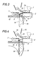
- the longitudinal slide 8 of the pick-up 7 is moved to the counter-holder 11 with the clamping finger 9 extended and the workpiece W clamped (FIG. 3) at the appropriate moment, for example in half the workpiece, without the Sewing process must be interrupted.
- Further sewing or further conveying of the workpiece W by the conveyor 24 also pushes the remaining workpiece part beyond the end of the table, so that the workpiece W turns over the clamping finger 9 and hangs together on the clamping finger.
- the swivel arm 10 closes and the workpiece is fixed by the holding clip formed from the clamping finger 9 and the swivel arm 10.
- the guide finger 19 pivots to the workpiece holder 3 and, in the case of a workpiece threaded onto the guide finger 19 with an opening, the cross slide 20 can move a corresponding distance to clamp the workpiece, so that this workpiece is spread between the clamping finger 19 and the holding clamp (Fig .4).
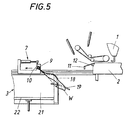
- the carriage 8 now only needs to travel up to the support 3, the workpiece being lifted by the guide finger 19 and the guide plate 18 with the parts hanging down during this carriage movement (FIG. 5), and the workpiece comes after removal to lie properly on the shelf 22 or an already existing workpiece stack by the guide finger.
- the shelf 22 must be brought into the appropriate position, depending on the stack height, so as not to impede the stacking of the workpieces.
- the workpiece is released by swiveling the swivel arm 10 and retracting the clamping finger 9 and the customer 7 can move back to the machine table 2 to take over the next workpiece W, whereupon the holding-down device 23 possibly compresses the stack in the storage 3. Since the workpiece storage over the pickup 7 is carried out independently of the machining process by the sewing machine 1, overlapping work is possible and the placement of the workpieces does not entail a delay in the workflow.
Landscapes
- Engineering & Computer Science (AREA)
- Textile Engineering (AREA)
- Sewing Machines And Sewing (AREA)
- Warehouses Or Storage Devices (AREA)
Abstract
Description
Die Erfindung bezieht sich auf eine Zusatzvorrichtung für Nähmaschinen od. dgl. zum Ablegen der bearbeiteten Werkstücke, insbesondere Wäsche- und Kleiderzuschnitte, mit einer dem Maschinentisch nachgeordneten Werkstückablage und vorzugsweise einem die abzulegenden Werkstücke in Vorschubrichtung über den Tisch weiterfördernden Förderer.The invention relates to an additional device for sewing machines or the like. For storing the machined workpieces, in particular laundry and clothing blanks, with a workpiece shelf downstream of the machine table and preferably with a conveyor further conveying the workpieces in the feed direction over the table.
Die Herstellung von Kleidungsstücken oder anderen textilen Produkten erfolgt meist in mehreren Arbeitsschritten, wobei jeder Arbeitsschritt auf einer gesonderten Bearbeitungsmaschine durchgeführt wird. So werden beispielsweise Wäscheund Kleiderzuschnitte nacheinander auf verschiedenen Nähmaschinen mit den erforderlichen Verbindungs- und Ziernähten, Säumen, Bünden, Gummizügen usw. versehen und die Werkstücke müssen dazu nach jedem Bearbeitungsschritt von der jeweiligen Bearbeitungsmaschine abgelegt und der nächsten Bearbeitungsmaschine zugebracht werden. Bisher ist es notwendig, die Werkstücke nach der jeweiligen Bearbeitung händisch vom Maschinentisch abzunehmen und in eine Werkstückablage zu legen oder sie nach einem entsprechend verlängerten Vorschub vom Maschinentisch in einen Ablagekorb od. dgl. abfallen zu lassen. Dadurch ergeben sich nicht nur längere Unterbrechungen des eigentlichen Bearbeitungsvorganges, sondern die Werkstücke werden unregelmäßig und ungeordnet abgelegt und mossen daher for den nächsten Arbeitsschritt mühsam und zeitraubend wieder bearbeitungsgerecht zusammengelegt und lagerichtig sortiert werden.The production of clothing or other textile products usually takes place in several work steps, with each work step being carried out on a separate processing machine. For example, laundry and clothing cuts are successively provided on various sewing machines with the necessary connecting and decorative seams, hems, frets, elastic bands, etc., and the workpieces have to be removed from the respective processing machine after each processing step and brought to the next processing machine. So far, it has been necessary to manually remove the workpieces from the machine table after each machining operation to be placed in a workpiece holder or, after a correspondingly extended feed, let it fall off the machine table into a storage basket or the like. This not only results in longer interruptions to the actual machining process, but the workpieces are deposited irregularly and in an unordered manner and therefore had to be laboriously and time-consuming to put together again for the next work step and be sorted in the correct position.
Der Erfindung liegt daher die Aufgabe zugrunde, diese Mängel zu beseitigen und eine Zusatzvorrichtung der eingangs geschilderten Art zu schaffen, die ein automatisches Ablegen der bearbeiteten Werkstücke erlaubt und dabei ein Zusammenlegen dieser Werkstücke mit sich bringt.The invention is therefore based on the object of eliminating these deficiencies and of creating an additional device of the type described at the outset, which allows the machined workpieces to be deposited automatically and thereby brings these workpieces together.
Die Erfindung löst diese Aufgabe dadurch, daß ein vom Maschinentisch bis über die vorzugsweise als Fach mit höhenverstellbarem Boden ausgebildete Werkstückablage hin- und herbewegbarer Abnehmer vorgesehen ist, der einen quer zur Vorschubrichtung liegenden, im Bereich des Tischendes mit einem Gegenhalter zusammenwirkenden Klemmfinger zum Festklemmen eines teilweise über das Tischende hinausgeschobenen Werkstückes aufweist. Ist ein Werkstück während oder auch nach der Bearbeitung so weit zum Tischende hin vorgeschoben, daß ein gewünschter Werkstückteil, beispielsweise eine Werkstückhälfte vom Tischende herabhängt, wird der Abnehmer zum Maschinentisch hin in Klemmposition gefahren, wodurch das Werkstück an der gewünschten Stelle zwischen Klemmfinger und Gegenhalter festgeklemmt wird und ein weiterer Werkstückvorschub den noch am Tisch liegenden Werkstückteil über den Klemmfinger hinweg schiebt, bis er vom Tisch abrutscht und das Werkstück über dem Klemmfinger hängt. Nun braucht der Abnehmer nur mehr zur Werkstückablage hinbewegt zu werden und der Klemmfinger (bringt das Werkstück zur Ablage, wo es auf den Boden oder den bereits vorhandenen Werkstückstapel aufgelegt wird. Ein Zurockfahren des Abnehmers führt den Klemmf inger aus dem Werkstück heraus und erlaubt das Klemmen und Übernehmen des nächsten Werkstückes. Als Gegenhalter dient vorteilhafterweise direkt ein Teil der Stirnseite des Tischendes, die mit einer entsprechenden Auflage versehen sein kann. Selbstverständlich ist es auch möglich, einen eigenen Gegenhalter zu montieren, der sogar wegschwenkbar am Abnehmer gelagert sein kann und das Festklemmen des Werkstückes auch während des Transportes zur Werkstückablage ermöglichen wurde. Allerdings müßte dann unterhalb des Tisches genogend Platz zum Hintergreifen des Werkstückes durch den schwenkbaren Gegenhalter vorhanden sein.The invention solves this problem in that a reciprocable from the machine table to the preferably designed as a compartment with a height-adjustable workpiece rest is provided, which has a cross finger to the direction of movement, cooperating in the area of the table end with a counterholder for clamping a part workpiece pushed out over the table end. If a workpiece is pushed so far towards the end of the table during or after machining that a desired workpiece part, e.g. one half of the workpiece, hangs from the end of the table, the pickup is moved to the machine table in the clamping position, whereby the workpiece is clamped at the desired location between the clamping finger and the counterhold and another workpiece feed pushes the part of the workpiece still on the table over the clamping finger until it slips off the table and the workpiece hangs over the clamping finger. Now the customer only needs to be moved to the workpiece holder and the clamping finger (brings the workpiece for storage where it is placed on the floor or the existing stack of workpieces. A rocking of the pickup leads the clamping finger out of the workpiece and allows the next workpiece to be clamped and accepted. A part of the end face of the table end, which can be provided with a corresponding support, advantageously serves directly as a counter-holder. Of course, it is also possible to mount your own counterholder, which can even be pivoted away on the customer and which would also enable the workpiece to be clamped during transport to the workpiece holder. However, there would have to be enough space below the table for the workpiece to be gripped behind by the swiveling counter-holder.
Um das Ablegen der Werkstücke in der Werkzeugablage zu erleichtern, ist erfindungsgemäß der Klemmfinger ein- und ausfahrbar gelagert, so daß beim Zurückfahren des Abnehmers der Klemmfinger nicht mehr durch das zusammengelegte Werkstück herausbewegt werden muß, sondern das Werkstück durch das Einfahren des Klemmfingers freigegeben wird. Vor dem Klemmen eines neuen Werkstückes ist dann der Klemmfinger wieder auszufahren und wirkt ordnungsgemäß mit dem Gegenhalter als Klemme zusammen.In order to make it easier to place the workpieces in the tool holder, the clamping finger is, according to the invention, mounted so that it can be extended and retracted, so that when the customer moves back the clamping finger no longer has to be moved out by the folded workpiece, but the workpiece is released by retracting the clamping finger. Before clamping a new workpiece, the clamping finger has to be extended again and works properly with the counter holder as a clamp.
Nach einer besonders gonstigen Ausgestaltung der Erfindung trägt der Abnehmer einen an der gegenhalterabgewandten Seite mit dem Klemmfinger eine Halteklammer bildenden Schwenkarm, so daß das Werkstück bei der Übergabe vom Tisch an die Werkstückablage festgeklemmt ist und nicht lose am Klemmfinger hängt. Dieser Schwenkarm ersetzt einen schwenkbaren Gegenhalter, so daß es keine Platzprobleme gibt und die Werkstücke immer unmittelbar vom Tisch über den Gegenhalter geschoben werden und nicht erst im hängenden Zustand zwischen Gegenhalter und Klemmfinger einge klemmt werden müssen, was einen störungsfreien Ablegevorgang garantiert.According to a particularly inexpensive embodiment of the invention, the customer carries a swivel arm forming a retaining clip on the side facing away from the counter-holder with the clamping finger, so that the workpiece is clamped during transfer from the table to the workpiece holder and does not hang loosely on the clamping finger. This swivel arm replaces a swiveling counter-holder, so that there are no space problems and the workpieces are always pushed directly from the table over the counter-holder and are not inserted between the counter-holder and the clamping finger in the hanging state must be clamped, which guarantees a trouble-free depositing process.
Günstig ist es weiters, wenn im Endbereich des Maschinentisches eine von der Arbeitsfläche des Tisches abwärts in den Klemmbereich von Gegenhalter und Klemmfinger führende Gleitplatte vorgesehen ist, die Durchblasöffnungen besitzt und in Vorschubrichtung auf die Durchblasöffnungen ausgerichtete Luftdosen überdeckt. Durch diese Gleitbahn und den durch die Düsen erzeugten Luftstrom läßt sich das Umschlagen des bereits durch den Klemmfinger und den Gegenhalter festgehaltenen Werkstückes um den Klemmfinger unterstützen und der Abnahmevorgang beschleunigen.It is also expedient if, in the end region of the machine table, a sliding plate is provided which leads from the work surface of the table down into the clamping region of the counter-holder and clamping finger, which has blow-through openings and covers air cans aligned with the blow-through openings in the feed direction. Through this slideway and the air flow generated by the nozzles, the turning over of the workpiece already held by the clamping finger and the counterholder can be supported around the clamping finger and the removal process can be accelerated.
Eine zusätzliche Verbesserung dieses Abnehmens wird außerdem durch im Endbereich des Tisches oberhalb dessen Arbeitsfläche in und/oder gegen die Vorschubrichtung abwärts geneigt angeordnete Luftdüsen erreicht, die mit ihren Luftstrahlen einerseits die Umschlagbewegung des Werkstückes erleichtern und anderseits ein Glätten der hängenden Werkstückteile erlauben.An additional improvement in this removal is also achieved by air nozzles arranged at an angle in the end region of the table above and in relation to the feed direction, which on the one hand facilitate the turning movement of the workpiece with their air jets and on the other hand allow the hanging workpiece parts to be smoothed.
Ist erfindungsgemäß zwischen Tisch und Ablage eine Leiteinrichtung für die vom Abnehmer zur Ablage gebrachten Werkstücke vorgesehen, wird ein ordnungsgemäßes flaches Ablegen der Werkstücke in der Ablage sichergestellt, da durch die Leiteinrichtung die vom Klemmfinger herabhängenden Werkstückteile angehoben und ablagegerecht ausgerichtet werden können.If, according to the invention, a guide device is provided between the table and the tray for the workpieces brought by the customer to the tray, a correct, flat placement of the workpieces in the tray is ensured, since the workpiece parts hanging from the clamping finger can be raised and aligned in accordance with the guide device.
Als Leiteinrichtung genügt beispielsweise ein ansteigend zur Ablagehöhe verlaufendes Leitblech, dem die Werkstücke entlang hochgezogen werden, oder eine in Ablagehöhe querverlaufende Leitstange, über die die Werkstücke zu ziehen sind, doch ist es besonders vorteilhaft, wenn die Leit einrichtung einen an der dem Abnehmer gegenüberliegenden Seite des Maschinentisches angeordneten, frei hochragenden Führungsfinger aufweist, der um eine Querachse zur Vorschubrichtung zwischen Ablage und Maschinentisch hin- und herschwenkbar gelagert ist. Ein solcher Führungsfinger läßt sich bei Werkstücken mit entsprechenden Löchern, beispielsweise bei Zuschnitten für Unterhosen u. dgl., in ein entsprechendes Loch des festgeklemmten Werkstückes einschwenken, so daß das um den Klemmfinger umgeschlagene Werkstück dann mit dem Loch auf dem Finger aufgefädelt ist. Wird hierauf der Führungsfinger in den Ablagebereich umgeschwenkt, ergibt sich für das Werkstück während der Abnehmerbewegung vom Maschinentisch zur Ablage entlang des Führungsfingers eine exakte, saübere Führung.As a guide device, for example, a baffle that rises to the storage height and the workpieces are pulled up along, or a guide rod that runs transversely at the storage height and over which the workpieces are to be pulled is sufficient, but it is particularly advantageous if the guide device has a freely projecting guide finger arranged on the side of the machine table opposite the customer, which is pivotably mounted about a transverse axis to the direction of advance between the tray and the machine table. Such a guide finger can be used for workpieces with corresponding holes, for example when cutting underpants u. Like., Swing into a corresponding hole in the clamped workpiece so that the workpiece folded over the clamping finger is then threaded with the hole on the finger. If the guide finger is then swiveled into the storage area, the workpiece is precisely and cleanly guided along the guide finger during the removal movement from the machine table to the storage area.
Ist der Führungsfinger in Richtung zur Ablage hin gekrümmt, werden auf einfache Weise die Führungseigenschaften des Führungsfingers verbessert und durch einen entsprechenden seitlichen Verlauf der Krümmung läßt sich auch während der Führungsbewegung des Werkstückes entlang des Führungsfingers ein das Werkstück ausbreitender Effekt erreichen.If the guide finger is curved in the direction of the rest, the guide properties of the guide finger are improved in a simple manner, and a corresponding lateral course of the curvature can also achieve an effect which spreads the workpiece during the guide movement of the workpiece along the guide finger.
Sitzt nach einer Weiterbildung der Erfindung der Führungsfinger auf einem quer zur Vorschubrichtung verschiebbaren Querschlitten, kann das Ausbreiten und Auflegen der Werkstücke bei der Übergabe vom Maschinentisch zur Ablage auf das jeweilige Werkstück selbst abgestimmt und für einen funktionssicheren Ablauf gesorgt werden. Der Führungsfinger braucht dazu ja nur nach dem Einfädeln in das Werkstückloch bis zum entsprechenden Spannen des Werkstückes querverschoben zu werden, so daß nach einem Zurückschwenken in Ablagerichtung das Werkstück mit dem Abnehmer ausgespannt und ausgebreitet in die Werkstückablage kommt.If, according to a development of the invention, the guide finger is seated on a cross slide that can be moved transversely to the feed direction, the spreading and placement of the workpieces can be coordinated with the transfer from the machine table to the respective workpiece itself and a functionally reliable process can be ensured. The guide finger only needs to be moved after threading into the workpiece hole until the workpiece is clamped accordingly, so that after swiveling back in the storage direction, the workpiece is stretched out with the customer and spread out into the workpiece holder.
Nach einer weiteren Ausgestaltung der Erfindung ist das Fach der Werkstückablage mit einem von oben zum Boden hin absenkbaren Druckstempel ausgerüstet, durch den die in der Ablage abgelegten Werkstücke flachgedrückt und einwandfrei gestapelt werden können, wozu noch kommt, daß durch ein entsprechendes Zusammenwirken von Druckstempelund Abnehmer-Rückbewegung eine zusätzliche Hilfe für den eigentlichen Stapelvorgang der Werkstücke in der Ablage erreicht werden kann.According to a further embodiment of the invention, the compartment of the workpiece holder is equipped with a pressure stamp which can be lowered from the top to the bottom, by means of which the workpieces placed in the holder can be flattened and stacked perfectly, which is further compounded by a corresponding interaction of the stamp and the customer. Return movement an additional help for the actual stacking of the workpieces in the tray can be achieved.
In der Zeichnung ist der Erfindungsgegenstand rein schematisch veranschaulicht, und zwar zeigen
- Fig. 1 und 2 eine erfindungsgemäße Zusatzvorrichtung in Seiten- und Stirnansicht und die
- Fig. 3 bis 5 verschiedene Arbeitsphasen dieser Zusatzvorrichtung an Hand schematischer Teilansichten.
- 1 and 2 an additional device according to the invention in side and front view and
- 3 to 5 different working phases of this additional device on the basis of schematic partial views.
Um auf einer Nähmaschine 1 bearbeitete Werkstücke automatisch vom Maschinentisch 2 abnehmen und für eine Weiterverarbeitung griffgerecht in eine Werkstückablage 3 ablegen zu können, gibt es eine Zusatzvorrichtung 4, die einen entlang einer seitlich neben der Arbeitsfläche 5 des Arbeitstisches 2 vorgesehenen Längsführung 6 zwischen dem Maschinentisch 2 und der Werkstückablage 3 hin- und herverfahrbaren Abnehmer 7 aufweist. Dieser Abnehmer 7 besteht aus einem Längsschlitten 8, auf dem ein quer zur Vorschubrichtung liegender ein- und ausfahrbarer Klemmfinger 9 sowie ein mit dem Klemmfinger 9 eine Halteklammer bildender auf- und zuschwenkbarer Schwenkarm 10 gelagert sind. Dem Klemmfinger 9 ist im Endbereich des Maschinentisches 2 ein Gegenhalter 11 zugeordnet, so daß durch ein entsprechendes Heranfahren des Abnehmers 7 an den Maschinentisch 2 ein vom Tisch 2 herabhängendes Werkstück zwischen Gegenhalter 11 und Klemmfinger 9 festgeklemmt werden kann.In order to be able to automatically remove workpieces machined on a
Der Maschinentisch 2 ist in seinem Endbereich mit einer gelochten Gleitplatte 12 versehen, die von der Tischoberfläche zum Gegenhalter 11 führt und Luftdüsen 13 überdeckt, die in Vorschubrichtung des Werkstückes durch die Durchblasöffnungen 14 der Gleitplatte 12 gerichtet sind. Oberhalb des Klemmbereiches zwischen Gegenhalter 11 und Klemmfinger 9 sind zusätzlich abwärts gerichtete Luftdüsen 15,16 angeordnet, welche Luftdüsen durch entsprechende Luftbeaufschlagung die Werkstückbewegung bei der Übergabe an den Abnehmer 7 unterstützen.The machine table 2 is provided in its end region with a
Zwischen dem Maschinentisch 2 und der Werkstückablage 3 ist unterhalb des Abnehmers 7 eine Leiteinrichtung 17 vorgesehen, die ein ordentliches Überbringen der Werkstücke vom Maschinentisch 2 in die Ablage 3 durch den Abnehmer 7 gewährleisten soll. Diese Leiteinrichtung 17 besteht aus einem Führungsblech 18 im Bereich der Abnehmerseite und aus einem frei hochragenden Führungsfinger 19 auf der dem Abnehmer gegenüberliegenden Seite des Maschinentisches 2, welcher Führungsfinger 19 um eine Querachse zur Vorschubrichtung schwenkbar auf einem quer zur Vorschubrichtung verschiebbaren Querschlitten 20 sitzt und zwischen Werkstückablage 3 und Maschinentisch 2 hin- und herschwenkbar ist. Führungsblech 18 und Führungsfinger 19 sind zur Ablage 3 hin gekrümmt, so daß die vom Abnehmer 7 zur Ablage 3 hin mitgenommenen Werkstücke endseitig angehoben und flach in die Ablage abgelegt werden.Between the machine table 2 and the
Die Werkstückablage 3 ist als oben offenes Fach 21 ausgebildet, das einen der Höhe nach verstellbaren Boden 22 zur Abstimmung der Fachtiefe auf den vorhandenen Werkstückstapel aufweist und mit einem von oben auf einen solchen Werkstückstapel absenkbaren Druckstempel 23 zum Zusammendrücken dieses Stapels ausgerüstet ist.The
Die Nähmaschine 1 oder eine andere Bearbeitungsmaschine kann auf jede geeignete Art ausgebildet und ausgerüstet sein, wobei vorteilhafterweise ein die bearbeiteten Werkstücke in Vorschubrichtung über den Tisch weiterfördernder Förderer 24 vorgesehen ist, der die Werkstücke ohne ein händisches Zutun sicher bis in den Bereich des Abnehmers 7 bzw. des Gegenhalters 11 bringt. Als Antriebe für die einzelnen Bewegungsabläufe können an sich ebenfalls beliebige Einrichtungen vorgesehen sein, doch eignen sich vor allem Pneumatikzylinder 25, 26, 27, 28, 29, 30, 31 for die Stellbewegungen von Längsschlitten 8, Klemmfinger 9, Schwenkarm 10, Führungsfinger 19 und dessen Querschlitten 20 sowie auch des Fachbodens 22 und des Druckstempels 23, da es hier um einfache Hubbewegungen bestimmter Größe geht, die aufwandsarm und exakt durch entsprechende Beaufschlagung der Pneumatikzylinder durchgeführt werden können.The
Wird nun ein Werkstück W auf der Nähmaschine 1 bearbeitet, sorgt der Förderer 24 dafür, daß die bereits genähten Werkstückteile über den Maschinentisch 2 weitergeschoben werden, bis sie über die Gleitplatte 12 und den Gegenhalter 11 hinweg vom Tisch herabhängen. In Abhängigkeit von der Nählänge bzw. der Stichzahl wird im entsprechenden Augenblick, beispielsweise in der Hälfte des Werkstückes der Längschlitten 8 des Abnehmers 7 mit ausgefahrenem Klemmfinger 9 an den Gegenhalter 11 herangefahren und das Werkstuck W festgeklemmt (Fig. 3), ohne daß dabei der Nähvorgang unterbrochen werden muß. Ein Weiternähen bzw. ein Weiterfördern des Werkstückes W durch den Förderer 24 schiebt den restlichen Werkstückteil ebenfalls über das Tischende hinaus, so daß das Werkstück W über den Klemmfinger 9 umschlägt und zusammengelegt am Klemmfinger hängt. Dieses Umschlagen des Werkstückes W wird durch entsprechende Luftbeaufschlagung der Luftdüsen 13, 15, 16 unterstützt, welche Luftstrahlen auch für ein glattes Hängen des Werkstückes auf dem Klemmfinger 9 sorgen. Gleichzeitig mit dem Festklemmen des Werkstückes zwischen Klemmfinger 9 und Gegenhalter 11 wird der Führungsfinger 19 der Leiteinrichtung 17 zum Maschinentisch 2 hin verschwenkt, so daß beim Umschlagen des Werkstückes um den Klemmfinger 9 eine gegebenenfalls vorhandene Werkstücköffnung auf den Führungsfinger 19 aufgefädelt wird.If a workpiece W is now processed on the
Hängt das bearbeitete Werkstück W auf dem Klemmfinger 9, schließt der Schwenkarm 10 und das Werkstück ist durch die aus Klemmfinger 9 und Schwenkarm 10 gebildete Halteklammer fixiert. Nun schwenkt der Führungsfinger 19 zur Werkstückablage 3 und im Falle eines mit einer Öffnung auf den Führungsfinger 19 aufgefädelten Werkstückes kann der Querschlitten 20 zum Spannen des Werkstückes ein entsprechendes Stück nach außen fahren, so daß dieses Werkstück zwischen Klemmfinger 19 und der Halteklammer aufgebreitet wird (Fig.4). Der Schlitten 8 braucht jetzt nur mehr bis über die Auflage 3 zu fahren, wobei während dieser Schlittenbewegung das Werkstück durch den Führungsfinger 19 und das Führungsblech 18 mit den nach unten hängenden Teilen angehoben wird (Fig. 5), und das Werkstück kommt nach dem Abziehen vom Führungsfinger ordnungsgemäß auf dem Fachboden 22 oder einem bereits vorhandenen Werkstückstapel zu liegen. Selbstverständlich muß der Fachboden 22 je nach Stapelhöhe in die entsprechende Lage gebracht werden, um das Aufschichten der Werkstücke nicht zu behindern.If the machined workpiece W hangs on the clamping
Nun wird das Werkstück durch ein Zurückschwenken des Schwenkarmes 10 und ein Einfahren des Klemmfingers 9 freigegeben und der Abnehmer 7 kann zur Übernahme des nächsten Werkstückes W zum Maschinentisch 2 zurückfahren, worauf gegebenenfalls der Niederhalter 23 den Stapel in der Ablage 3 zusammendrückt. Da die Werkstückablage über den Abnehmer 7 unabhängig vom Bearbeitungsvorgang durch die Nähmaschine 1 erfolgt, ist ein überlappendes Arbeiten möglich und das Ablegen der Werkstücke bringt keine Verzögerung des Arbeitsablaufes mit sich.Now the workpiece is released by swiveling the
Da durch das Zusammenlegen der Werkstücke bei der Übergabe an den Abnehmer die beim Nähen außenliegende Werkstückseite umgeschlagen wird, kommt es bei dieser Ablage nicht nur zu einem Zusammenlegen, sondern auch zu einem loseitenwechsel, so daß sich die Werkstücke durch dieses Ablegen für einen nächsten Arbeitsschritt optimal vorbereiten lassen. Werden beispielsweise Unterhosenzuschnitte, die bereits bis auf eine Seitennaht genäht sind, auf der Nähmaschine 1 mit einem Bundband versehen, das an der Außenseite der Zuschnitte aufgenäht werden muß, werden diese Zuschnitte beim Zusammenlegen im Bereich der vorhanden Seitennaht umgeklappt, und für das abschließende Setzen der zweiten Seitennaht, die innenseitig aufgebracht wird, ist das Werkstück bereits ordnungsgemäß zusammengelegt und nähgerecht mit der Innenseite nach außen gedreht, so daß ohne weitere Handgriffe diese Zuschnitte nach dem Bundaufnähen sofort im nächsten Arbeitsgang mit der Seitennaht versehen werden können.Since the folding of the workpieces at the handover to the customer turns over the outside of the workpiece when sewing, this storage not only results in a folding, but also in a change of sides, so that the workpieces are optimal for this next work step get prepared. If, for example, underpants that have already been sewn except for a side seam are provided on the
Claims (10)
Applications Claiming Priority (2)
| Application Number | Priority Date | Filing Date | Title |
|---|---|---|---|
| AT215689A AT397971B (en) | 1989-09-15 | 1989-09-15 | ADDITIONAL DEVICE FOR SEWING MACHINES OD. DGL. FOR DEPOSITING THE WORKED WORKPIECES |
| AT2156/89 | 1989-09-15 |
Publications (2)
| Publication Number | Publication Date |
|---|---|
| EP0418215A1 true EP0418215A1 (en) | 1991-03-20 |
| EP0418215B1 EP0418215B1 (en) | 1994-01-05 |
Family
ID=3528959
Family Applications (1)
| Application Number | Title | Priority Date | Filing Date |
|---|---|---|---|
| EP19900890260 Expired - Lifetime EP0418215B1 (en) | 1989-09-15 | 1990-09-11 | Auxiliary device for sewing machines or the like for deposing workpieces |
Country Status (5)
| Country | Link |
|---|---|
| EP (1) | EP0418215B1 (en) |
| JP (1) | JPH03170195A (en) |
| AT (1) | AT397971B (en) |
| DE (1) | DE59004114D1 (en) |
| ES (1) | ES2047908T3 (en) |
Citations (3)
| Publication number | Priority date | Publication date | Assignee | Title |
|---|---|---|---|---|
| FR2326525A1 (en) * | 1975-10-02 | 1977-04-29 | Rockwell Rimoldi Spa | STACKING DEVICE FOR GARMENTS IN A SEWING UNIT |
| EP0201408A1 (en) * | 1985-04-29 | 1986-12-17 | Eminence S.A. | Stacking device for textile work pieces |
| DE8700117U1 (en) * | 1987-01-03 | 1987-04-23 | Zawischka, Dieter, 7410 Reutlingen, De |
Family Cites Families (3)
| Publication number | Priority date | Publication date | Assignee | Title |
|---|---|---|---|---|
| DE2312878C3 (en) * | 1973-03-15 | 1980-05-22 | Duerkoppwerke Gmbh, 4800 Bielefeld | Multipurpose device for holding flexible workpieces |
| DE2627006C3 (en) * | 1976-06-16 | 1981-06-04 | Dürkoppwerke GmbH, 4800 Bielefeld | Device for laying large, flexible workpieces on top of one another, spread out flat |
| DE2649471C2 (en) * | 1976-10-29 | 1978-12-21 | Pfaff Industriemaschinen Gmbh, 6750 Kaiserslautern | Device for removing and collecting flexible workpieces on a sewing machine |
-
1989
- 1989-09-15 AT AT215689A patent/AT397971B/en not_active IP Right Cessation
-
1990
- 1990-09-11 DE DE90890260T patent/DE59004114D1/en not_active Expired - Fee Related
- 1990-09-11 EP EP19900890260 patent/EP0418215B1/en not_active Expired - Lifetime
- 1990-09-11 ES ES90890260T patent/ES2047908T3/en not_active Expired - Lifetime
- 1990-09-14 JP JP24286790A patent/JPH03170195A/en active Pending
Patent Citations (3)
| Publication number | Priority date | Publication date | Assignee | Title |
|---|---|---|---|---|
| FR2326525A1 (en) * | 1975-10-02 | 1977-04-29 | Rockwell Rimoldi Spa | STACKING DEVICE FOR GARMENTS IN A SEWING UNIT |
| EP0201408A1 (en) * | 1985-04-29 | 1986-12-17 | Eminence S.A. | Stacking device for textile work pieces |
| DE8700117U1 (en) * | 1987-01-03 | 1987-04-23 | Zawischka, Dieter, 7410 Reutlingen, De |
Also Published As
| Publication number | Publication date |
|---|---|
| AT397971B (en) | 1994-08-25 |
| ES2047908T3 (en) | 1994-03-01 |
| JPH03170195A (en) | 1991-07-23 |
| EP0418215B1 (en) | 1994-01-05 |
| ATA215689A (en) | 1993-12-15 |
| DE59004114D1 (en) | 1994-02-17 |
Similar Documents
| Publication | Publication Date | Title |
|---|---|---|
| EP0128487B2 (en) | Machine-tool having a stationary magazine | |
| CH684345A5 (en) | Method and apparatus for folding a flat, foldable workpiece. | |
| DE2924017A1 (en) | DEVICE FOR ATTACHING ELASTIC RINGS TO TUBULAR CLOTHING | |
| DE2456789C2 (en) | Sewing machine | |
| DE3709210C2 (en) | ||
| EP0100420A1 (en) | Apparatus for handling workpieces | |
| DE4013066C2 (en) | Bobbin changing device | |
| DE3709232C2 (en) | ||
| DE3709251C2 (en) | Sewing machine | |
| DE3709264C2 (en) | Sewing machine | |
| DE3725265A1 (en) | METHOD AND DEVICE FOR CHANGING SPIDER CAN IN A SPINNING PREPARATION MACHINE | |
| DE3212629C2 (en) | Device for folding clothing, in particular smocks | |
| CH673831A5 (en) | ||
| DE3823945C2 (en) | ||
| DE1660822B2 (en) | Device for forming a first workpiece and sewing it to a second workpiece | |
| EP0418215B1 (en) | Auxiliary device for sewing machines or the like for deposing workpieces | |
| DE4033177C2 (en) | Device for feeding or transferring a small workpiece | |
| EP0426886B1 (en) | Method of operation and apparatus for transferring, on the one side, bobbins from a winding, assembling or spinning machine to a bobbin conveyer and, on the other side, empty bobbins from the conveyer to the winding, assembling or spinning machine | |
| DE2835994A1 (en) | Sewing machine stitch chain control - has an alignment unit and suction section to align the chain in a given length for seam insertion | |
| DE19840749C2 (en) | Sewing unit for sewing on bags to be folded or pre-bent | |
| DE3010517C2 (en) | Folding machine with a paper feeder | |
| DE2935895C2 (en) | Machine for cleaning and separating ceramic bricks | |
| DE19722610A1 (en) | Method and device for folding and stacking material | |
| EP1158083B1 (en) | Device for changing the upper thread | |
| DE3514466C1 (en) | Device for skinning skins |
Legal Events
| Date | Code | Title | Description |
|---|---|---|---|
| PUAI | Public reference made under article 153(3) epc to a published international application that has entered the european phase |
Free format text: ORIGINAL CODE: 0009012 |
|
| AK | Designated contracting states |
Kind code of ref document: A1 Designated state(s): CH DE ES FR GB GR IT LI |
|
| 17P | Request for examination filed |
Effective date: 19910902 |
|
| 17Q | First examination report despatched |
Effective date: 19930622 |
|
| GRAA | (expected) grant |
Free format text: ORIGINAL CODE: 0009210 |
|
| AK | Designated contracting states |
Kind code of ref document: B1 Designated state(s): CH DE ES FR GB GR IT LI |
|
| REF | Corresponds to: |
Ref document number: 59004114 Country of ref document: DE Date of ref document: 19940217 |
|
| REG | Reference to a national code |
Ref country code: ES Ref legal event code: FG2A Ref document number: 2047908 Country of ref document: ES Kind code of ref document: T3 |
|
| GBT | Gb: translation of ep patent filed (gb section 77(6)(a)/1977) |
Effective date: 19940131 |
|
| ET | Fr: translation filed | ||
| ITF | It: translation for a ep patent filed |
Owner name: MODIANO & ASSOCIATI S.R.L. |
|
| REG | Reference to a national code |
Ref country code: GR Ref legal event code: FG4A Free format text: 3011347 |
|
| PLBE | No opposition filed within time limit |
Free format text: ORIGINAL CODE: 0009261 |
|
| STAA | Information on the status of an ep patent application or granted ep patent |
Free format text: STATUS: NO OPPOSITION FILED WITHIN TIME LIMIT |
|
| 26N | No opposition filed | ||
| PGFP | Annual fee paid to national office [announced via postgrant information from national office to epo] |
Ref country code: GR Payment date: 19980827 Year of fee payment: 9 |
|
| PGFP | Annual fee paid to national office [announced via postgrant information from national office to epo] |
Ref country code: GB Payment date: 19980901 Year of fee payment: 9 |
|
| PGFP | Annual fee paid to national office [announced via postgrant information from national office to epo] |
Ref country code: ES Payment date: 19980918 Year of fee payment: 9 |
|
| PGFP | Annual fee paid to national office [announced via postgrant information from national office to epo] |
Ref country code: FR Payment date: 19980924 Year of fee payment: 9 Ref country code: DE Payment date: 19980924 Year of fee payment: 9 |
|
| PGFP | Annual fee paid to national office [announced via postgrant information from national office to epo] |
Ref country code: CH Payment date: 19981001 Year of fee payment: 9 |
|
| PG25 | Lapsed in a contracting state [announced via postgrant information from national office to epo] |
Ref country code: GB Free format text: LAPSE BECAUSE OF NON-PAYMENT OF DUE FEES Effective date: 19990911 |
|
| PG25 | Lapsed in a contracting state [announced via postgrant information from national office to epo] |
Ref country code: ES Free format text: LAPSE BECAUSE OF NON-PAYMENT OF DUE FEES Effective date: 19990912 |
|
| PG25 | Lapsed in a contracting state [announced via postgrant information from national office to epo] |
Ref country code: LI Free format text: LAPSE BECAUSE OF NON-PAYMENT OF DUE FEES Effective date: 19990930 Ref country code: GR Free format text: LAPSE BECAUSE OF NON-PAYMENT OF DUE FEES Effective date: 19990930 Ref country code: CH Free format text: LAPSE BECAUSE OF NON-PAYMENT OF DUE FEES Effective date: 19990930 |
|
| GBPC | Gb: european patent ceased through non-payment of renewal fee |
Effective date: 19990911 |
|
| REG | Reference to a national code |
Ref country code: CH Ref legal event code: PL |
|
| PG25 | Lapsed in a contracting state [announced via postgrant information from national office to epo] |
Ref country code: FR Free format text: LAPSE BECAUSE OF NON-PAYMENT OF DUE FEES Effective date: 20000531 |
|
| PG25 | Lapsed in a contracting state [announced via postgrant information from national office to epo] |
Ref country code: DE Free format text: LAPSE BECAUSE OF NON-PAYMENT OF DUE FEES Effective date: 20000701 |
|
| REG | Reference to a national code |
Ref country code: FR Ref legal event code: ST |
|
| REG | Reference to a national code |
Ref country code: ES Ref legal event code: FD2A Effective date: 20001013 |
|
| PG25 | Lapsed in a contracting state [announced via postgrant information from national office to epo] |
Ref country code: IT Free format text: LAPSE BECAUSE OF NON-PAYMENT OF DUE FEES;WARNING: LAPSES OF ITALIAN PATENTS WITH EFFECTIVE DATE BEFORE 2007 MAY HAVE OCCURRED AT ANY TIME BEFORE 2007. THE CORRECT EFFECTIVE DATE MAY BE DIFFERENT FROM THE ONE RECORDED. Effective date: 20050911 |