EP0417499A1 - Armoire de commutation avec une porte - Google Patents
Armoire de commutation avec une porte Download PDFInfo
- Publication number
- EP0417499A1 EP0417499A1 EP90115646A EP90115646A EP0417499A1 EP 0417499 A1 EP0417499 A1 EP 0417499A1 EP 90115646 A EP90115646 A EP 90115646A EP 90115646 A EP90115646 A EP 90115646A EP 0417499 A1 EP0417499 A1 EP 0417499A1
- Authority
- EP
- European Patent Office
- Prior art keywords
- flap
- cabinet door
- frame
- insert
- control cabinet
- Prior art date
- Legal status (The legal status is an assumption and is not a legal conclusion. Google has not performed a legal analysis and makes no representation as to the accuracy of the status listed.)
- Withdrawn
Links
Images


Classifications
-
- H—ELECTRICITY
- H02—GENERATION; CONVERSION OR DISTRIBUTION OF ELECTRIC POWER
- H02B—BOARDS, SUBSTATIONS OR SWITCHING ARRANGEMENTS FOR THE SUPPLY OR DISTRIBUTION OF ELECTRIC POWER
- H02B1/00—Frameworks, boards, panels, desks, casings; Details of substations or switching arrangements
- H02B1/26—Casings; Parts thereof or accessories therefor
- H02B1/30—Cabinet-type casings; Parts thereof or accessories therefor
- H02B1/306—Accessories, e.g. windows
Definitions
- the invention relates to a control cabinet with a cabinet door, into which a recess is made, which is covered by a frame.
- the frame around the recess of the cabinet door forms a holder for a window pane.
- the frame can be connected to a support plate on which controls can be attached.
- the space required for the installation of operating elements is very small since the frame should not protrude too much from the cabinet door.
- the frame is connected to a warmthenförmi gene insert which is inserted into the opening of the cabinet door, that the frame has a connecting portion which covers the edge region adjoining the opening on the outside of the cabinet door and on the outside of the frame in a U- open to the cabinet door
- Shaped end frame passes that egg ne flap is pivotally mounted in the region of the lower horizontal edge of the insert, which can be brought into a horizontal open position by means of flap holders or flap brakes and is held firmly therein and that the flap is covered by a closure element in the open side of the insert Locked position can be locked.
- the structure is simplified according to one embodiment in that the frame is integrally formed on the insert, preferably beveled.
- the connecting section is firmly connected to the cabinet door, e.g. screwed, is.
- the connecting section of the frame carries a sealing element on the outside and that the end frame receives a further sealing element in its open side, then the insert in the closing position of the flap is sealed and the frame also closes tightly to the cabinet door.
- the flap is used as a worktop, e.g. for storing a keyboard
- the upper side wall of the insert is inclined so that the interior increases towards the open side and that a lighting arrangement for illuminating the space above the folded-out flap is installed in the upper side wall.
- the securing of the objects placed on the folded-out flap can be achieved simply by the fact that the flap on the inside has a circumferential bend as a holder for objects placed on the flap, such as a keyboard.
- the flap on the outside on the edge opposite the articulation side carries a preferably bent grip strip.
- a visually appealing closure of the recess in the cabinet door can be achieved in that the closure frame has a section which is perpendicular to the cabinet door and merges into a section running parallel to the cabinet door, and in that the closure frame has an inclined section facing the outside towards the cabinet door is completed, which allows the width of the end frame to the cabinet door to increase, and in that the flap with the adjoining sides is rotatably mounted in the end frame and in the closed position is flush with the section of the end frame running parallel to the cabinet door.
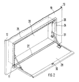
- Fig. 1 only a part of the cabinet door 10 can be seen, in which a rectangular opening 11 is made.
- the vertical edges of the cabinet door 10 are stiffened by the folds 12 and 13.
- the trough-shaped insert 20 is inserted, which merges in the region of the open side into a circumferential frame, not specified.
- the flap 28 is pivotally connected to the insert 20.
- the flap 28 is on both sides with one each of two articulated lifting In existing flap holder 29 held in the horizontal open position and can be used as an additional worktop or storage plate.
- the opposite of the articulation side 27 of the flap 28 is folded towards the outside as a grip strip 27 and provided with the closure element 30, which locks the flap 28 in the closed position, in which it closes the open side of the insert 20 flush with the frame.
- the frame height is deliberately kept small so that the installation is not bulky.
- the depth of the insert 20 depends on the space required for the objects to be installed or set and on the built-in components in the control cabinet, which must maintain the required distance from the back of the insert when the cabinet door is closed.
- two flap brakes 31 are provided instead of the two flap holders 29 for holding the flap 28 in place.
- Flap brakes 31 adjustable in braking force are preferably used, so that the lowering movement of the flap 28 can be adjusted with objects fastened thereon.
- the enlarged partial view according to FIG. 3 reveals the design of the frame folded on the insert.
- the outwardly directed connecting section 22 is attached to the open side of the insert 20, which at the end merges into the forward-facing and open to the cabinet door 10 from the sections 23, 24 and 25.
- the connecting section 22 and the section 24 run parallel to the cabinet door 10, while the section 23 is perpendicular thereto.
- the section 25 is inclined so that it is towards the cabinet door 10 the width of the U-shaped end frame enlarged.
- the sealing element 26 is applied, which takes over the sealing between the flap 28 and the insert 20 in the closed position of the flap 28.
- the connecting section 22 is fixedly connected to the edge area around the recess 11 of the cabinet door 10, for. B. screwed and even before the application of the sealing element 26.
- the open end frame with the sections 23, 24 and 25 receives the further sealing element 27, which takes over the sealing between the end frame and the cabinet door 10.
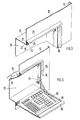
- Fig. 4 shows how a chamfered receptacle can be formed on the inside of the flap 28, in which e.g. a keyboard 33 is held. If the keyboard 33 is additionally connected to the flap 28, it can be brought into the closed position with the flap 28, in which it is received by the insert 20. The connecting cables of the keyboard 33 can be routed from the insert 20 into the control cabinet via cable bushings known per se.
- the upper side wall 21 of the insert 20 can also be inclined so that the interior of the insert 20 increases towards the open side, then the lighting arrangement 34 can be installed in the side wall 21 so that the unfolded on the Flap 28 is illuminated in the standing keyboard 33 formed by the folds 36.
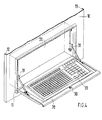
- Fig. 6 shows an embodiment in which the bottom of the insert 20 is used as a support plate for controls, etc.
- the depth of the insert 20 can also be kept smaller.
- 6 shows that the flap 28 with the the articulation side 27 adjoining sides in the end frame sections 23 is rotatably mounted, so that it is flush with the end frame sections 24 in the closed position.
- the locking element 30 can be a simple cam lock, which can be rotated by means of an actuating element and is introduced into a recess in the frame.
Applications Claiming Priority (2)
| Application Number | Priority Date | Filing Date | Title |
|---|---|---|---|
| DE3930188 | 1989-09-09 | ||
| DE3930188A DE3930188C1 (fr) | 1989-09-09 | 1989-09-09 |
Publications (1)
| Publication Number | Publication Date |
|---|---|
| EP0417499A1 true EP0417499A1 (fr) | 1991-03-20 |
Family
ID=6389106
Family Applications (1)
| Application Number | Title | Priority Date | Filing Date |
|---|---|---|---|
| EP90115646A Withdrawn EP0417499A1 (fr) | 1989-09-09 | 1990-08-16 | Armoire de commutation avec une porte |
Country Status (4)
| Country | Link |
|---|---|
| US (1) | US5082336A (fr) |
| EP (1) | EP0417499A1 (fr) |
| JP (1) | JP2809848B2 (fr) |
| DE (1) | DE3930188C1 (fr) |
Families Citing this family (28)
| Publication number | Priority date | Publication date | Assignee | Title |
|---|---|---|---|---|
| DE4310442C2 (de) * | 1992-03-31 | 1995-07-20 | Emka Beschlagteile | Klappenfeststellvorrichtung |
| DE9301698U1 (fr) * | 1993-02-08 | 1993-04-15 | Schroff Gmbh, 7541 Straubenhardt, De | |
| DE4312816C2 (de) * | 1993-04-20 | 1995-03-30 | Loh Kg Rittal Werk | Schaltschrank mit einem in die Vorderfront eingebauten Kasten |
| US5836551A (en) * | 1996-07-26 | 1998-11-17 | Ortronics Corporation | Bottom pivot wallmount bracket and wire management system |
| US5842313A (en) * | 1996-09-24 | 1998-12-01 | American Access Technologies, Inc. | Communications cable interconnection apparatus and associated method for an open office architecture |
| US5911661A (en) * | 1996-09-24 | 1999-06-15 | American Access Technologies, Inc. | Zone cabling termination cabinet |
| DE19817918C1 (de) * | 1998-04-17 | 1999-11-25 | Loh Kg Rittal Werk | Fenstereinheit |
| US6220681B1 (en) * | 1999-03-11 | 2001-04-24 | Wellness, Llc | Armoire with built in desk |
| US6755491B2 (en) * | 2001-06-26 | 2004-06-29 | Mcelheney Billy W. | Operator interface terminal for use in a harsh environment |
| US20030039881A1 (en) * | 2001-08-22 | 2003-02-27 | Mount Robert L. | Battery accessible modules for rack mount systems |
| EP1365491A1 (fr) * | 2002-05-23 | 2003-11-26 | Jeepson Techno Services LLC | Armoire modulaire |
| US20030226323A1 (en) * | 2002-06-07 | 2003-12-11 | Travez Jose V. | Structure having preinstalled utilities and amenities |
| WO2004024509A1 (fr) * | 2002-09-10 | 2004-03-25 | Kabushiki Kaisha Kenwood | Dispositif electronique |
| US20050093404A1 (en) * | 2003-10-27 | 2005-05-05 | Donovan Robert F. | Mini communications center |
| US20050135068A1 (en) * | 2003-12-17 | 2005-06-23 | Huff Brian E. | Electronic equipment enclosure |
| US7231159B2 (en) * | 2005-06-14 | 2007-06-12 | Dell Products L.P. | Articulating user interface panel |
| DE102008019704A1 (de) * | 2008-04-18 | 2009-10-29 | MULTIVAC Sepp Hagemüller GmbH & Co. KG | Verpackungsmaschine mit Schaltschrank |
| USD767427S1 (en) | 2012-03-06 | 2016-09-27 | Western Systems, Inc. | Traffic control cabinet |
| US20140084766A1 (en) * | 2012-09-21 | 2014-03-27 | Western Systems, Inc. | Cabinet |
| US9236717B2 (en) | 2012-12-11 | 2016-01-12 | Panduit Corp. | Equipment segregation unit for an industrial control panel |
| US8919894B1 (en) * | 2013-06-18 | 2014-12-30 | Michael Barry Pachmayr | Flat panel console/cabinet entertainment center |
| USD961963S1 (en) | 2020-07-21 | 2022-08-30 | Walker Edison Furniture Company Llc | Desk |
| USD973396S1 (en) | 2020-07-22 | 2022-12-27 | Walker Edison Furniture Company Llc | Desk |
| USD961964S1 (en) | 2021-01-26 | 2022-08-30 | Walker Edison Furniture Company Llc | Desk |
| USD968126S1 (en) * | 2021-01-26 | 2022-11-01 | Walker Edison Furniture Company Llc | Desk |
| USD1012570S1 (en) | 2021-01-27 | 2024-01-30 | Walker Edison Furniture Company Llc | Desk |
| USD1003084S1 (en) | 2021-01-27 | 2023-10-31 | Walker Edison Furniture Company Llc | Desk |
| USD995162S1 (en) | 2021-07-27 | 2023-08-15 | Walker Edison Furniture Company Llc | Desk |
Citations (1)
| Publication number | Priority date | Publication date | Assignee | Title |
|---|---|---|---|---|
| DE1182322B (de) * | 1960-07-28 | 1964-11-26 | Christian Geyer | Verfahren zur Herstellung von Unterputz-zaehlerschraenken |
Family Cites Families (11)
| Publication number | Priority date | Publication date | Assignee | Title |
|---|---|---|---|---|
| US491641A (en) * | 1893-02-14 | Grain-binding harvester | ||
| US1320392A (en) * | 1919-11-04 | William f | ||
| US492867A (en) * | 1893-03-07 | Cotton-chopper | ||
| US1023425A (en) * | 1911-11-27 | 1912-04-16 | Joseph J Harrison | Wall-safe. |
| US3054212A (en) * | 1961-03-24 | 1962-09-18 | Morris Lester | Soap dish |
| US3854248A (en) * | 1973-05-21 | 1974-12-17 | L Dayus | Duct access door |
| DE2847994C2 (de) * | 1978-11-06 | 1984-11-08 | Rittal-Werk Rudolf Loh Gmbh & Co Kg, 6348 Herborn | Rahmenprofil für Fenster- und Türrahmen von Schaltschränken |
| JPH0328535Y2 (fr) * | 1986-03-06 | 1991-06-19 | ||
| DE8619379U1 (de) * | 1986-07-18 | 1986-08-28 | Bündoplast bopla Gehäuse Systeme GmbH, 4980 Bünde | Gehäuse zum Einsetzen in Schalttafeln |
| US4810025A (en) * | 1987-01-27 | 1989-03-07 | Recreational Components, Inc. | Rain deflector for motor home utility door |
| DE8907155U1 (fr) * | 1989-06-10 | 1989-10-26 | Apra-Geraetebau Ing.Grad. Wolfgang Appenzeller Und Wilfried Rademacher, 5568 Daun, De |
-
1989
- 1989-09-09 DE DE3930188A patent/DE3930188C1/de not_active Expired - Fee Related
-
1990
- 1990-08-16 EP EP90115646A patent/EP0417499A1/fr not_active Withdrawn
- 1990-09-07 US US07/579,624 patent/US5082336A/en not_active Expired - Lifetime
- 1990-09-10 JP JP2237305A patent/JP2809848B2/ja not_active Expired - Fee Related
Patent Citations (1)
| Publication number | Priority date | Publication date | Assignee | Title |
|---|---|---|---|---|
| DE1182322B (de) * | 1960-07-28 | 1964-11-26 | Christian Geyer | Verfahren zur Herstellung von Unterputz-zaehlerschraenken |
Non-Patent Citations (1)
| Title |
|---|
| IBM TECHNICAL DISCLOSURE BULLETIN. vol. 3, no. 3, August 1960, NEW YORK US Seiten 21 - 22; Pittwood: "Control panel closure mechanism" * |
Also Published As
| Publication number | Publication date |
|---|---|
| JP2809848B2 (ja) | 1998-10-15 |
| JPH03107311A (ja) | 1991-05-07 |
| DE3930188C1 (fr) | 1991-01-31 |
| US5082336A (en) | 1992-01-21 |
Similar Documents
| Publication | Publication Date | Title |
|---|---|---|
| EP0417499A1 (fr) | Armoire de commutation avec une porte | |
| DE19811714C2 (de) | Bausatz für einen Schaltschrank | |
| DE69911868T2 (de) | Rückwandtüranordnung | |
| EP0706012A1 (fr) | Four de boulanger | |
| DE19507731C1 (de) | Schaltschrank mit Schranktür und Dachhaube | |
| EP1475008B1 (fr) | Valise | |
| EP0176890B1 (fr) | Armoire de manoeuvre comprenant un châssis métallique à plusieurs jambes | |
| EP0807371B1 (fr) | Armoire de distribution avec baie et plaque de montage | |
| DE7817270U1 (de) | Wandsafe | |
| EP0236809A2 (fr) | Bureau support d'appareils, en particulier d'informatique | |
| DE19711094B4 (de) | Kabelsammler | |
| DE19811713C2 (de) | Schaltschrank | |
| EP0952649A1 (fr) | Armoire de distribution avec boîtier intérieur pour blindage HF | |
| DE3008934C2 (de) | Abfallsammler aus einem Füllbehälter und einem Deckel | |
| DE2528951B2 (de) | Verschlußdeckel für den Dosenkasten einer Unterflurgerätedose | |
| DE19745757A1 (de) | Abdeckleiste | |
| DE4128355C1 (en) | Electronic equipment housing e.g. TV, radio cabinet, allowing access for servicing - has frame for walls using plug flaps fitting grooves and held in place by spring-loaded fasteners releasable by operating elements | |
| DE8209700U1 (de) | Verschlussvorrichtung fuer den gepaeckraum eines kraftfahrzeuges, insbesondere eines omnibusses | |
| DE3544372C2 (fr) | ||
| DE7328782U (de) | Glastürschloß | |
| DE19841998C1 (de) | Gehäuse mit einem frontseitig offenen Gehäuseteil | |
| DE102004022474B4 (de) | Schacht mit Klappdeckel | |
| DE2531084C3 (de) | Ausstellvorrichtung für Kipp-, Klapp- o.dgl. Flügel von Fenstern, Türen o.dgl. | |
| EP0338341A2 (fr) | Armoire de commutation à cadre pivotant | |
| AT410627B (de) | Metallschrank |
Legal Events
| Date | Code | Title | Description |
|---|---|---|---|
| PUAI | Public reference made under article 153(3) epc to a published international application that has entered the european phase |
Free format text: ORIGINAL CODE: 0009012 |
|
| AK | Designated contracting states |
Kind code of ref document: A1 Designated state(s): AT BE CH DE DK ES FR GB GR IT LI LU NL SE |
|
| 17P | Request for examination filed |
Effective date: 19910124 |
|
| 17Q | First examination report despatched |
Effective date: 19920907 |
|
| STAA | Information on the status of an ep patent application or granted ep patent |
Free format text: STATUS: THE APPLICATION IS DEEMED TO BE WITHDRAWN |
|
| 18D | Application deemed to be withdrawn |
Effective date: 19931012 |