EP0415780A1 - Transformation électromécanique le long d'un chemin - Google Patents
Transformation électromécanique le long d'un chemin Download PDFInfo
- Publication number
- EP0415780A1 EP0415780A1 EP90309539A EP90309539A EP0415780A1 EP 0415780 A1 EP0415780 A1 EP 0415780A1 EP 90309539 A EP90309539 A EP 90309539A EP 90309539 A EP90309539 A EP 90309539A EP 0415780 A1 EP0415780 A1 EP 0415780A1
- Authority
- EP
- European Patent Office
- Prior art keywords
- path
- accordance
- along
- improvement
- electromechanical transducer
- Prior art date
- Legal status (The legal status is an assumption and is not a legal conclusion. Google has not performed a legal analysis and makes no representation as to the accuracy of the status listed.)
- Granted
Links
Images


Classifications
-
- B—PERFORMING OPERATIONS; TRANSPORTING
- B60—VEHICLES IN GENERAL
- B60G—VEHICLE SUSPENSION ARRANGEMENTS
- B60G17/00—Resilient suspensions having means for adjusting the spring or vibration-damper characteristics, for regulating the distance between a supporting surface and a sprung part of vehicle or for locking suspension during use to meet varying vehicular or surface conditions, e.g. due to speed or load
- B60G17/015—Resilient suspensions having means for adjusting the spring or vibration-damper characteristics, for regulating the distance between a supporting surface and a sprung part of vehicle or for locking suspension during use to meet varying vehicular or surface conditions, e.g. due to speed or load the regulating means comprising electric or electronic elements
- B60G17/019—Resilient suspensions having means for adjusting the spring or vibration-damper characteristics, for regulating the distance between a supporting surface and a sprung part of vehicle or for locking suspension during use to meet varying vehicular or surface conditions, e.g. due to speed or load the regulating means comprising electric or electronic elements characterised by the type of sensor or the arrangement thereof
- B60G17/01933—Velocity, e.g. relative velocity-displacement sensors
-
- B—PERFORMING OPERATIONS; TRANSPORTING
- B60—VEHICLES IN GENERAL
- B60G—VEHICLE SUSPENSION ARRANGEMENTS
- B60G13/00—Resilient suspensions characterised by arrangement, location or type of vibration dampers
- B60G13/14—Resilient suspensions characterised by arrangement, location or type of vibration dampers having dampers accumulating utilisable energy, e.g. compressing air
-
- B—PERFORMING OPERATIONS; TRANSPORTING
- B60—VEHICLES IN GENERAL
- B60G—VEHICLE SUSPENSION ARRANGEMENTS
- B60G13/00—Resilient suspensions characterised by arrangement, location or type of vibration dampers
- B60G13/16—Resilient suspensions characterised by arrangement, location or type of vibration dampers having dynamic absorbers as main damping means, i.e. spring-mass system vibrating out of phase
- B60G13/18—Resilient suspensions characterised by arrangement, location or type of vibration dampers having dynamic absorbers as main damping means, i.e. spring-mass system vibrating out of phase combined with energy-absorbing means
-
- B—PERFORMING OPERATIONS; TRANSPORTING
- B60—VEHICLES IN GENERAL
- B60G—VEHICLE SUSPENSION ARRANGEMENTS
- B60G17/00—Resilient suspensions having means for adjusting the spring or vibration-damper characteristics, for regulating the distance between a supporting surface and a sprung part of vehicle or for locking suspension during use to meet varying vehicular or surface conditions, e.g. due to speed or load
- B60G17/015—Resilient suspensions having means for adjusting the spring or vibration-damper characteristics, for regulating the distance between a supporting surface and a sprung part of vehicle or for locking suspension during use to meet varying vehicular or surface conditions, e.g. due to speed or load the regulating means comprising electric or electronic elements
- B60G17/0152—Resilient suspensions having means for adjusting the spring or vibration-damper characteristics, for regulating the distance between a supporting surface and a sprung part of vehicle or for locking suspension during use to meet varying vehicular or surface conditions, e.g. due to speed or load the regulating means comprising electric or electronic elements characterised by the action on a particular type of suspension unit
- B60G17/0157—Resilient suspensions having means for adjusting the spring or vibration-damper characteristics, for regulating the distance between a supporting surface and a sprung part of vehicle or for locking suspension during use to meet varying vehicular or surface conditions, e.g. due to speed or load the regulating means comprising electric or electronic elements characterised by the action on a particular type of suspension unit non-fluid unit, e.g. electric motor
-
- H—ELECTRICITY
- H02—GENERATION; CONVERSION OR DISTRIBUTION OF ELECTRIC POWER
- H02K—DYNAMO-ELECTRIC MACHINES
- H02K35/00—Generators with reciprocating, oscillating or vibrating coil system, magnet, armature or other part of the magnetic circuit
- H02K35/02—Generators with reciprocating, oscillating or vibrating coil system, magnet, armature or other part of the magnetic circuit with moving magnets and stationary coil systems
-
- H—ELECTRICITY
- H02—GENERATION; CONVERSION OR DISTRIBUTION OF ELECTRIC POWER
- H02K—DYNAMO-ELECTRIC MACHINES
- H02K41/00—Propulsion systems in which a rigid body is moved along a path due to dynamo-electric interaction between the body and a magnetic field travelling along the path
- H02K41/02—Linear motors; Sectional motors
- H02K41/03—Synchronous motors; Motors moving step by step; Reluctance motors
- H02K41/031—Synchronous motors; Motors moving step by step; Reluctance motors of the permanent magnet type
-
- B—PERFORMING OPERATIONS; TRANSPORTING
- B60—VEHICLES IN GENERAL
- B60G—VEHICLE SUSPENSION ARRANGEMENTS
- B60G2202/00—Indexing codes relating to the type of spring, damper or actuator
- B60G2202/20—Type of damper
- B60G2202/25—Dynamic damper
-
- B—PERFORMING OPERATIONS; TRANSPORTING
- B60—VEHICLES IN GENERAL
- B60G—VEHICLE SUSPENSION ARRANGEMENTS
- B60G2202/00—Indexing codes relating to the type of spring, damper or actuator
- B60G2202/40—Type of actuator
- B60G2202/42—Electric actuator
- B60G2202/422—Linear motor
-
- B—PERFORMING OPERATIONS; TRANSPORTING
- B60—VEHICLES IN GENERAL
- B60G—VEHICLE SUSPENSION ARRANGEMENTS
- B60G2300/00—Indexing codes relating to the type of vehicle
- B60G2300/60—Vehicles using regenerative power
-
- B—PERFORMING OPERATIONS; TRANSPORTING
- B60—VEHICLES IN GENERAL
- B60G—VEHICLE SUSPENSION ARRANGEMENTS
- B60G2400/00—Indexing codes relating to detected, measured or calculated conditions or factors
- B60G2400/25—Stroke; Height; Displacement
- B60G2400/252—Stroke; Height; Displacement vertical
-
- B—PERFORMING OPERATIONS; TRANSPORTING
- B60—VEHICLES IN GENERAL
- B60G—VEHICLE SUSPENSION ARRANGEMENTS
- B60G2500/00—Indexing codes relating to the regulated action or device
- B60G2500/10—Damping action or damper
-
- B—PERFORMING OPERATIONS; TRANSPORTING
- B60—VEHICLES IN GENERAL
- B60G—VEHICLE SUSPENSION ARRANGEMENTS
- B60G2500/00—Indexing codes relating to the regulated action or device
- B60G2500/20—Spring action or springs
-
- B—PERFORMING OPERATIONS; TRANSPORTING
- B60—VEHICLES IN GENERAL
- B60G—VEHICLE SUSPENSION ARRANGEMENTS
- B60G2500/00—Indexing codes relating to the regulated action or device
- B60G2500/30—Height or ground clearance
-
- B—PERFORMING OPERATIONS; TRANSPORTING
- B60—VEHICLES IN GENERAL
- B60G—VEHICLE SUSPENSION ARRANGEMENTS
- B60G2600/00—Indexing codes relating to particular elements, systems or processes used on suspension systems or suspension control systems
- B60G2600/22—Magnetic elements
- B60G2600/26—Electromagnets; Solenoids
-
- B—PERFORMING OPERATIONS; TRANSPORTING
- B60—VEHICLES IN GENERAL
- B60G—VEHICLE SUSPENSION ARRANGEMENTS
- B60G2600/00—Indexing codes relating to particular elements, systems or processes used on suspension systems or suspension control systems
- B60G2600/76—Digital systems
Definitions
- the present invention relates in general to electromechanical transducing along a path and more particularly concerns an along-path, typically linear, controllable force source typically embodying novel apparatus and techniques for actively absorbing energy from a vehicle wheel assembly moving over a rough surface so as to facilitate significantly reducing forces transmitted to the vehicle body supported on the wheel assembly.
- a typical active control system uses wheel forces, car accelerations, or other vehicle parameters to determine when to open/close valves which allow fluid to flow, thereby moving the piston of the actuator in such a manner as to absorb shock.
- the wheel assembly in a vehicle having a chassis and at least one wheel assembly, where the wheel assembly includes a wheel support member, may include a damping mass, may include a damping spring for connecting the damping mass to the wheel support member, and may include a mechanical resistive member in parallel with the damping spring, a suspension connecting the wheel assembly to the chassis, the suspension supporting the weight of the vehicle and isolating the wheel motion from the chassis motion, and at least one actuator for providing force between the wheel assembly and the chassis, the improvement includes a controllable along-path electromechanical transducer connected between the wheel assembly and the chassis, where the controllable along-path electromechanical transducer provides controllable force between the wheel assembly and the chassis and may convert mechanical energy produced by mechanical movement into electrical energy that may be returned to a vehicle battery or otherwise used in the vehicle.
- An along-path electromechanical transducer has first and second elements relatively movable along a path between first and second ends as distinguished from a conventional motor having a stator and rotating armature. This combination including the damping mass allows control at all meaningful frequencies, including wheel resonance, while significantly reducing force transmission to the suspended mass without excessive energy dissipation.
- controllable along-path electromechanical transducer is a linear multipole motor with salient poles.
- the improvement may further include a load-leveling device connected between the wheel assembly and the chassis, the load-leveling device providing force between the wheel assembly and the chassis to compensate for the weight of the loaded vehicle where the load-leveling device may include an air bag.
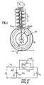
- Fig. 1 there is shown a combined block-diagrammatic representation of a typical prior art wheel suspension.
- the sprung mass of the vehicle typically comprising about one-fourth the mass of the vehicle including the frame and components supported thereon, is connected to wheel assembly 12 by spring 13 in parallel with shock absorber 14.
- Wheel support assembly 12 carries on axle 12A wheel 15 including hub 15B and tire 15C.
- the wheel, brake assembly and wheel support assembly are characterized by an unsprung mass M w .
- the brake assembly may be a part of the unsprung mass.
- Tire 15C has a compliance C T .
- Tire 15C is shown supported on road 16.
- Spring 13 is characterized by a compliance C s
- shock absorber 14 is characterized by a mechanical resistance R SH .
- the shock absorber is replaced by an actuator which responds according to commands from a control system (not shown).
- V R represents the rate of change of the elevation of the road at the point of contact with the surface of tire 15C and is applied to the tire compliance 15C′ in series with the spring compliance 13′ in series with the vehicle sprung mass portion 11′.
- the spring compliance 13′ is shunted by the shock resistance 14′.
- the series combination of compliance 13′ in shunt with the shock resistance 14′ and the sprung mass 11′ is shunted by the wheel unsprung mass 15′.
- This mechanical circuit is characterized by resonances where the tire compliance C T resonates with the unsprung mass M w , and the spring compliance, C s , resonates with the sprung mass, M c .
- Fig. 3 there is shown a combined block-diagrammatic representation of a system 20 according to the invention incorporating an active vehicle suspension actuator and a damping assembly.
- Sprung mass portion 11 is connected to wheel support member 12 by active suspension actuator 22.
- Active suspension actuator 22 is electrically controlled by electronic controller 24.
- a damping assembly including damping mass 26 is connected to wheel support member 12 by damping spring 28 in parallel with damping resistance 30, which may be a conventional shock absorber.
- Fig. 3A is a schematic circuit diagram of the system of Fig. 3.
- Active suspension actuator 22 includes linear electric motor 32 (shown in Fig. 4), i.e., a device which converts electrical energy into mechanical work along a path, typically a straight line, without an intermediate rotary motion.
- Linear electric motor 32 is a controllable force source which for a constant control signal, maintains a constant force independent of position or velocity between the wheel assembly and the chassis. Any variation in force that is desired may be effected by correspondingly varying the control signal.
- electromechanical transducer While it is convenient to refer to the electromechanical transducer as an electric motor, it is to be understood that electric motor 32 embodying this transducer may also function as a generator to convert mechanical work into electrical energy that may charge the vehicle battery or otherwise usefully energize vehicle electrical components.
- motor 32 has multiple poles; i.e., the motor employs a magnetic field structure, produced by e.g., permanent magnets, field windings or induction, which has two or more field reversals over the normal range of travel.
- Motor 32 is preferably arranged to maximize the mechanical power it can provide for a given electrical power input while minimizing moving mass, e.g., by using salient-poles.
- a separate load leveling system e.g., a conventional air-bag system having a compressor, height sensor and controllable valve, may be employed.
- a load leveling system e.g., a conventional air-bag system having a compressor, height sensor and controllable valve.
- the mass of the motor part connected to the wheel support member is as low as practical.
- Electronic controller 24 for linear electric motor 32 includes commutation and cogging correction circuit 102 and power processor 104.
- Cogging forces are rectilinear forces, dependent on position, between relatively movable motor members with no current applied to the motor.
- Motor 32 includes position sensor 106 which detects the relative position between relatively movable motor members.
- Correction circuit 102 includes summer 110 which adds the commanded signal with the output of anti-cog compensator 112, which is a function of the output from position sensor 106.
- the output of position sensor 106 also energizes commutation waveform generator 114, which receives the output of summer 110 and outputs three command control signals, I a , I b , I c , to power processor 104.
- Power processor 104 includes three switching current mode control circuits 116, 118, 120 which provide the inputs to linear motor 32.
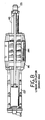
- FIG. 5 there is shown a perspective view of an exemplary embodiment of a linear motor according to the invention.
- This linear motor includes an inside member 131 of relatively low mass relatively movable with respect to an outside member 132.
- the exposed end of inside member 131 includes a bushing 133 connected to the unsprung mass, such as comprising the wheel assembly.
- Outside member 132 is pivotally connected at the end opposite bushing 133 to support member 134 attached to the sprung mass, such as the vehicle body.
- Dust cover 135 helps protect inside member 131 from dust.
- FIG. 6 there is shown a perspective view of the linear motor of Fig. 5. with side cap 136 (Fig. 5) and most of dust cover 135 removed to expose additional structural details.
- Outside member mounting frame 137 is connected to outside member pole assembly 141.
- Inside member 131 includes a number of rectangular magnets such as 142 and a sensor magnet holder 143 related to position sensor 6.
- Outside member 132 also includes coils, such as 144, and linear bearings, such as 145, that engage a bearing rail, such as 146 and 147.
- FIG. 7 there is shown a perspective view of the linear motor of Figs. 5 and 6 with outside member pole assembly 141 also removed to illustrate the coils, such as 144.
- FIG. 8 there is shown a view through section 8-8 of Fig. 5.
- This embodiment of a linear motor has a number of features and advantages.
- the relative force between inside member 131 and outside member 132 is related to the magnitude and polarity of the currents in the coils.
- the linear motor may thus be regarded as a source of electrically controllable relative force between sprung and unsprung masses.
- Sensor magnet holder 143 preferably carries an array of contiguous permanent magnet elements with alternating magnetic polarity to facilitate using a magnetic pickup head to sense flux changes as relative displacement occurs between the inside and outside members.
- a Gray code arrangement provides a digital signal representative of the absolute displacement between inside and outside members relative to a reference position.
- a feature of the invention is that motor 32 may at times function as a generator and convert mechanical work produced by relative movement between the suspended and unsuspended masses into electrical energy. This electrical energy is typically returned to the power supply for the switching amplifiers connected to the windings. These switching amplifiers typically include diodes across controllable power semiconductor switching devices such as transistors, FET's, IGBT's or SCR's so that energy may flow from motor 32 into the power supply through the shunting diodes. This feature effectively reduces the electrical power required to operate the system.
- Another feature of the invention resides in the ability to short-circuit the windings and thereby allow linear motor 32 to function as a passive damper or shock absorber. It may be desirable to effect this mode of operation when the active suspension system is malfunctioning or it is desired to reduce electrical energy consumption. Short-circuiting may be effected by operating one or more relays having normally open contacts across the motor windings. Alternatively, the power supply for the switching circuits may be crowbarred so that current may flow through the shunting diodes and thereby effectively provide magnetic damping.
- a feature of the inside and outside members is that there is core symmetry so that there is a neutral bearing force.
- the first and second members are substantially symmetrical about a surface parallel to the path of relative motion therebetween.
- the first and second elements are substantially symmetrical about a plane midway between planes tangential to extreme broad surfaces of the members and parallel to the path of relative motion.
- This symmetrical structure helps minimize the relative force between the first and second members orthogonal to the path of relative motion, this orthogonal force being significantly less than the maximum relative force between the first and second members in a direction along the path. Typically this orthogonal force is very low and nearly zero.
- the use of a multiple phase system helps improve efficiency; that is, provides a relatively high ratio of mechanical work (force X distance) to input electrical energy.
Priority Applications (1)
| Application Number | Priority Date | Filing Date | Title |
|---|---|---|---|
| EP94107447A EP0616412A1 (fr) | 1989-08-31 | 1990-08-31 | Transducteur électromécanique pour suspension de véhicule |
Applications Claiming Priority (2)
| Application Number | Priority Date | Filing Date | Title |
|---|---|---|---|
| US07/401,947 US4981309A (en) | 1989-08-31 | 1989-08-31 | Electromechanical transducing along a path |
| US401947 | 1989-08-31 |
Related Child Applications (1)
| Application Number | Title | Priority Date | Filing Date |
|---|---|---|---|
| EP94107447.8 Division-Into | 1990-08-31 |
Publications (2)
| Publication Number | Publication Date |
|---|---|
| EP0415780A1 true EP0415780A1 (fr) | 1991-03-06 |
| EP0415780B1 EP0415780B1 (fr) | 1994-11-30 |
Family
ID=23589919
Family Applications (2)
| Application Number | Title | Priority Date | Filing Date |
|---|---|---|---|
| EP94107447A Ceased EP0616412A1 (fr) | 1989-08-31 | 1990-08-31 | Transducteur électromécanique pour suspension de véhicule |
| EP90309539A Expired - Lifetime EP0415780B1 (fr) | 1989-08-31 | 1990-08-31 | Transformation électromécanique le long d'un chemin |
Family Applications Before (1)
| Application Number | Title | Priority Date | Filing Date |
|---|---|---|---|
| EP94107447A Ceased EP0616412A1 (fr) | 1989-08-31 | 1990-08-31 | Transducteur électromécanique pour suspension de véhicule |
Country Status (6)
| Country | Link |
|---|---|
| US (1) | US4981309A (fr) |
| EP (2) | EP0616412A1 (fr) |
| JP (2) | JPH0398455A (fr) |
| AT (1) | ATE114555T1 (fr) |
| CA (1) | CA2023839A1 (fr) |
| DE (1) | DE69014488T2 (fr) |
Cited By (13)
| Publication number | Priority date | Publication date | Assignee | Title |
|---|---|---|---|---|
| DE4204302A1 (de) * | 1991-02-14 | 1992-08-20 | Atsugi Unisia Corp | Elektromagnetische aufhaengungsvorrichtung |
| BE1006282A4 (fr) * | 1992-10-21 | 1994-07-12 | Babitz Jean | Amortisseur hydro-electrique. |
| FR2814985A1 (fr) * | 2000-10-11 | 2002-04-12 | Conception & Dev Michelin Sa | Dispositif de suspension comportant un verin electrique et un ressort en parallele |
| WO2002103721A1 (fr) * | 2001-06-19 | 2002-12-27 | Ahmad Razzaghi | Dispositif de puissance electromagnetique |
| US6619672B2 (en) | 2000-10-11 | 2003-09-16 | Conception Et Development Michelin S.A. | Suspension device having a trim corrector |
| EP1354732A2 (fr) * | 2002-04-17 | 2003-10-22 | Meritor Light Vehicle Technology, LLC | Système de suspension électromagnétique |
| FR2851742A1 (fr) * | 2003-02-28 | 2004-09-03 | Arslanian Pierre Jean Der | Suspension stabilisatrice pour l'asservissement d'attitude de vehicule roulants |
| EP1484201A1 (fr) * | 2003-06-02 | 2004-12-08 | Bose Corporation | Actionneur avec du filtre pour interference electromagnetique |
| EP1582383A1 (fr) * | 2004-03-31 | 2005-10-05 | CALZOLARI, Emanuele | Amortisseur de chocs à effet d'amortissement variable, notamment pour véhicules |
| EP1512559A3 (fr) * | 2003-09-08 | 2006-08-09 | Bose Corporation | Suspension active pour véhicule avec système de sûreté |
| US7962261B2 (en) | 2007-11-12 | 2011-06-14 | Bose Corporation | Vehicle suspension |
| US7983813B2 (en) | 2004-10-29 | 2011-07-19 | Bose Corporation | Active suspending |
| US8095268B2 (en) | 2004-10-29 | 2012-01-10 | Bose Corporation | Active suspending |
Families Citing this family (114)
| Publication number | Priority date | Publication date | Assignee | Title |
|---|---|---|---|---|
| KR940007210B1 (ko) * | 1989-11-29 | 1994-08-10 | 미쯔비시 덴끼 가부시끼가이샤 | 자동차용 현가장치 |
| US5337845A (en) * | 1990-05-16 | 1994-08-16 | Hill-Rom Company, Inc. | Ventilator, care cart and motorized transport each capable of nesting within and docking with a hospital bed base |
| JPH0490916A (ja) * | 1990-08-06 | 1992-03-24 | Honda Motor Co Ltd | 車両用サスペンション装置の制御方法 |
| EP0636287B1 (fr) * | 1992-04-15 | 1999-11-10 | Noise Cancellation Technologies, Inc. | Systeme de regulation de vibrations ameliore au moyen d'un resonateur adaptable |
| US5258904A (en) * | 1992-04-23 | 1993-11-02 | Ford Motor Company | Dither control method of PWM inverter to improve low level motor torque control |
| US6032770A (en) * | 1993-04-12 | 2000-03-07 | Raytheon Company | Low force actuator for suspension control |
| US5441298A (en) * | 1993-10-22 | 1995-08-15 | Ford Motor Company | Apparatus for stabilizing an electric active suspension system upon interruption of the power supply |
| JPH10501897A (ja) * | 1993-12-09 | 1998-02-17 | ディーン・ディベロップメンツ・リミテッド | 移動制御システム |
| US5701039A (en) * | 1995-07-20 | 1997-12-23 | Bose Corporation | Electromechanical transducing |
| IT1289322B1 (it) * | 1996-01-19 | 1998-10-02 | Carlo Alberto Zenobi | Dispositivo per l'ottenimento di energia elettrica dalle azioni dinamiche derivanti dal moto relativo tra veicoli e suolo |
| US5806111A (en) * | 1996-04-12 | 1998-09-15 | Hill-Rom, Inc. | Stretcher controls |
| EP0878333B1 (fr) * | 1997-05-16 | 2003-08-27 | Conception et Développement Michelin | Dispositif de suspension comportant un correcteur de ressort |
| DE19820617C2 (de) † | 1998-05-08 | 2002-11-07 | Karmann Gmbh W | Kraftfahrzeug mit Schwingungsdämpfungseinrichtung |
| US6364078B1 (en) * | 1998-08-27 | 2002-04-02 | Bose Corporation | Wheel damping |
| FR2795509B1 (fr) * | 1999-06-23 | 2001-09-14 | Peugeot Citroen Automobiles Sa | Dispositif de mesure du debattement lineaire d'un amortisseur de vehicule automobile |
| US6330926B1 (en) | 1999-09-15 | 2001-12-18 | Hill-Rom Services, Inc. | Stretcher having a motorized wheel |
| US7195250B2 (en) * | 2000-03-27 | 2007-03-27 | Bose Corporation | Surface vehicle vertical trajectory planning |
| EP1138530B1 (fr) | 2000-03-27 | 2013-11-06 | Bose Corporation | Planification de la trajectoire verticale pour un véhicule terrestre |
| US7014000B2 (en) * | 2000-05-11 | 2006-03-21 | Hill-Rom Services, Inc. | Braking apparatus for a patient support |
| CN101791261B (zh) | 2000-05-11 | 2013-04-24 | 希尔-罗姆服务股份有限公司 | 病人支撑台的机动牵引装置 |
| DE10038950A1 (de) * | 2000-08-09 | 2002-03-07 | Siemens Ag | Linearmotor |
| US20060237242A1 (en) * | 2000-09-25 | 2006-10-26 | Burke Robert J | Lightweight surface vehicle |
| CN101134430A (zh) * | 2000-09-25 | 2008-03-05 | Its巴士股份有限公司 | 可以承受的交通运输的平台 |
| US6561325B2 (en) | 2001-07-19 | 2003-05-13 | Dana Corporation | Vehicle suspension with remote spring |
| DE10139861B4 (de) | 2001-08-14 | 2004-07-01 | Daimlerchrysler Ag | Radaufhängung eines Kraftfahrzeugs |
| JP2005502433A (ja) | 2001-09-20 | 2005-01-27 | ヒル−ロム サービシーズ,インコーポレイティド | ベッドムーバと患者移動装置の組合せ |
| US7018157B2 (en) | 2001-09-20 | 2006-03-28 | Hill-Rom Services, Inc. | Powered transport apparatus for a bed |
| US6841970B2 (en) | 2002-12-20 | 2005-01-11 | Mark Zabramny | Dual-use generator and shock absorber assistant system |
| US6945541B2 (en) | 2003-01-21 | 2005-09-20 | Bose Corporation | Vehicle suspension |
| US7087342B2 (en) | 2003-04-15 | 2006-08-08 | Visteon Global Technologies, Inc. | Regenerative passive and semi-active suspension |
| JP4438406B2 (ja) * | 2003-06-27 | 2010-03-24 | アイシン精機株式会社 | スタビライザ制御装置 |
| KR100534700B1 (ko) * | 2003-08-13 | 2006-01-09 | 현대자동차주식회사 | 자동차의 서스펜션 및 그 제어방법 |
| US7654540B2 (en) * | 2004-06-18 | 2010-02-02 | Bose Corporation | Electromechanical transducing |
| US7421954B2 (en) * | 2004-06-18 | 2008-09-09 | Bose Corporation | Active suspension controller |
| DE102004030472A1 (de) * | 2004-06-24 | 2006-01-19 | Adam Opel Ag | Fahrwerk für Kraftfahrzeuge |
| DE102005043429A1 (de) * | 2005-05-19 | 2006-11-23 | Fraunhofer-Gesellschaft zur Förderung der angewandten Forschung e.V. | Vorrichtung zur Schwingungsentkopplung |
| US7401520B2 (en) * | 2005-08-26 | 2008-07-22 | Bose Corporation | Vehicle testing apparatus for applying vertical force to a wheel |
| US7934725B2 (en) * | 2005-08-29 | 2011-05-03 | Mobile Intelligence Corporation | Vehicle system and method for accessing denied terrain |
| JP4396611B2 (ja) | 2005-10-07 | 2010-01-13 | トヨタ自動車株式会社 | 車両用懸架シリンダ装置 |
| US20070113070A1 (en) | 2005-11-04 | 2007-05-17 | Lackritz Neal M | Secure active suspension system |
| US7810818B2 (en) * | 2005-11-29 | 2010-10-12 | Dariusz Antoni Bushko | Active vehicle suspension system |
| US7823891B2 (en) | 2005-11-29 | 2010-11-02 | Bose Corporation | Active vehicle suspension system |
| US7810822B2 (en) | 2006-01-19 | 2010-10-12 | Hill-Rom Services, Inc. | Stretcher having hand actuated caster braking apparatus |
| JP4743276B2 (ja) * | 2006-03-22 | 2011-08-10 | トヨタ自動車株式会社 | 車両用サスペンションシステム |
| US7886377B2 (en) * | 2006-10-13 | 2011-02-15 | Hill-Rom Services, Inc. | Push handle with rotatable user interface |
| US7882582B2 (en) * | 2006-10-13 | 2011-02-08 | Hill-Rom Services, Inc. | User interface and control system for powered transport device of a patient support apparatus |
| US8067863B2 (en) * | 2007-01-18 | 2011-11-29 | Bose Corporation | Detent force correcting |
| US7865983B2 (en) * | 2007-04-26 | 2011-01-11 | Hill-Rom Services, Inc. | Patient care equipment support transfer system |
| JP2008286362A (ja) * | 2007-05-21 | 2008-11-27 | Aisin Seiki Co Ltd | サスペンション装置 |
| US7789187B2 (en) * | 2008-01-29 | 2010-09-07 | Hill-Rom Services, Inc. | Push handle with pivotable handle post |
| US7953537B2 (en) * | 2008-02-29 | 2011-05-31 | Hill-Rom Services, Inc. | Algorithm for power drive speed control |
| US7804210B2 (en) * | 2008-03-25 | 2010-09-28 | Bose Corporation | Position measurement using magnetic fields |
| US7932684B2 (en) * | 2008-03-25 | 2011-04-26 | Bose Corporation | Absolute position sensing |
| US7994742B2 (en) * | 2008-03-25 | 2011-08-09 | Bose Corporation | Position measurement using magnetic fields |
| WO2009122954A1 (fr) * | 2008-04-02 | 2009-10-08 | 日産自動車株式会社 | Appareil et procédé de commande du pilotage d'actionneur à moteur électrique, et véhicule comportant cet appareil de commande d'entraînement d'actionneur à moteur électrique |
| US8839920B2 (en) | 2008-04-17 | 2014-09-23 | Levant Power Corporation | Hydraulic energy transfer |
| US8376100B2 (en) * | 2008-04-17 | 2013-02-19 | Levant Power Corporation | Regenerative shock absorber |
| US20090261665A1 (en) * | 2008-04-17 | 2009-10-22 | Leao Wang | Electromagnetic vibrating mechanism |
| US8392030B2 (en) * | 2008-04-17 | 2013-03-05 | Levant Power Corporation | System and method for control for regenerative energy generators |
| US7963529B2 (en) | 2008-09-08 | 2011-06-21 | Bose Corporation | Counter-rotating motors with linear output |
| US8757308B2 (en) * | 2009-09-10 | 2014-06-24 | Hill-Rom Services Inc. | Powered transport system and control methods |
| US8624699B2 (en) | 2009-11-09 | 2014-01-07 | Nucleus Scientific, Inc. | Electric coil and method of manufacture |
| US8585062B2 (en) | 2009-11-09 | 2013-11-19 | Nucleus Scientific, Inc. | Tunable pneumatic suspension |
| US8519575B2 (en) * | 2009-11-09 | 2013-08-27 | Nucleus Scientific, Inc. | Linear electric machine with linear-to-rotary converter |
| US8362660B2 (en) * | 2009-11-09 | 2013-01-29 | Nucleus Scientific, Inc. | Electric generator |
| CN105386951B (zh) | 2010-06-16 | 2021-11-16 | 动态清晰公司 | 整合式能量产生阻尼器 |
| DE102010038281A1 (de) * | 2010-07-22 | 2012-01-26 | Robert Bosch Gmbh | Energierekuperation aus einer Fahrzeugfederung |
| US8424888B2 (en) * | 2010-08-26 | 2013-04-23 | General Electric Company | Systems and methods for weight transfer in a vehicle |
| US8766493B2 (en) * | 2011-07-01 | 2014-07-01 | Nucleus Scientific, Inc. | Magnetic stator assembly |
| US8833780B2 (en) * | 2011-12-22 | 2014-09-16 | Hong Kong Productivity Council | Active suspension system and method |
| DE102011057062A1 (de) | 2011-12-27 | 2013-06-27 | iOLS GmbH | Fahrzeug |
| CN102616102B (zh) * | 2012-04-12 | 2013-10-23 | 江苏大学 | 汽车制动能量与悬架振动能量回收系统与方法 |
| JP5152545B1 (ja) * | 2012-04-16 | 2013-02-27 | 有限会社 加納 | リニア発電装置 |
| DE102012007519A1 (de) * | 2012-04-17 | 2013-10-17 | Rheinisch-Westfälische Technische Hochschule Aachen | Verfahren zur Fahrwerksabstimmung eines Kraftfahrzeugs und Federbein |
| US8938333B2 (en) | 2012-06-27 | 2015-01-20 | Bose Corporation | Active wheel damping |
| US9102209B2 (en) | 2012-06-27 | 2015-08-11 | Bose Corporation | Anti-causal vehicle suspension |
| US9707143B2 (en) | 2012-08-11 | 2017-07-18 | Hill-Rom Services, Inc. | Person support apparatus power drive system |
| US8725351B1 (en) | 2012-10-31 | 2014-05-13 | Bose Corporation | Active suspension system |
| KR101416362B1 (ko) * | 2012-11-15 | 2014-08-07 | 현대자동차 주식회사 | 차량용 서스펜션의 에너지 회생장치 |
| DE102012223359A1 (de) * | 2012-12-17 | 2014-06-18 | Robert Bosch Gmbh | Fahrwerkeinheit |
| RU2523540C1 (ru) * | 2013-03-14 | 2014-07-20 | Виктор Юрьевич Крылов | Исполнительное устройство системы стабилизации кузова транспортного средства |
| US9174508B2 (en) | 2013-03-15 | 2015-11-03 | Levant Power Corporation | Active vehicle suspension |
| WO2014145018A2 (fr) | 2013-03-15 | 2014-09-18 | Levant Power Corporation | Améliorations apportées à la suspension active d'un véhicule |
| US9702349B2 (en) | 2013-03-15 | 2017-07-11 | ClearMotion, Inc. | Active vehicle suspension system |
| JP6396414B2 (ja) | 2013-03-15 | 2018-09-26 | クリアモーション,インコーポレイテッド | 多経路流体ダイバータバルブ |
| US9855814B2 (en) | 2013-04-23 | 2018-01-02 | ClearMotion, Inc. | Active suspension with structural actuator |
| DE102013012637A1 (de) * | 2013-07-26 | 2015-01-29 | Audi Ag | Federsystem für eine Radaufhängung eines Kraftfahrzeugs |
| RO130499A2 (ro) | 2014-02-20 | 2015-08-28 | Schaeffler Technologies AG & Co.KG | Dispozitiv de reglare a înălţimii unei caroserii de vehicul |
| US9511644B2 (en) | 2014-09-18 | 2016-12-06 | Cnh Industrial America Llc | Liquid dispensing equipment with active suspension system |
| US9702424B2 (en) | 2014-10-06 | 2017-07-11 | ClearMotion, Inc. | Hydraulic damper, hydraulic bump-stop and diverter valve |
| US10300760B1 (en) | 2015-03-18 | 2019-05-28 | Apple Inc. | Fully-actuated suspension system |
| CN105711368B (zh) * | 2016-03-07 | 2018-01-30 | 大连理工大学 | 一种基于被动悬架的电磁俘能系统 |
| US10670748B2 (en) | 2016-08-18 | 2020-06-02 | Pgs Geophysical As | Systems and methods of a marine geophysical damper system |
| JP7211625B2 (ja) | 2016-09-13 | 2023-01-24 | インディゴ テクノロジーズ, インク. | マルチバーリンク機構電気駆動システム |
| US10493798B2 (en) | 2017-03-24 | 2019-12-03 | Cnh Industrial America Llc | Air strut suspension system for a self-propelled high ground clearance product applicator |
| US10814690B1 (en) | 2017-04-18 | 2020-10-27 | Apple Inc. | Active suspension system with energy storage device |
| JP2020518514A (ja) | 2017-05-08 | 2020-06-25 | アップル インコーポレイテッドApple Inc. | アクティブサスペンションシステム |
| US10899340B1 (en) | 2017-06-21 | 2021-01-26 | Apple Inc. | Vehicle with automated subsystems |
| US11173766B1 (en) | 2017-09-07 | 2021-11-16 | Apple Inc. | Suspension system with locking structure |
| US11065931B1 (en) | 2017-09-15 | 2021-07-20 | Apple Inc. | Active suspension system |
| US11124035B1 (en) | 2017-09-25 | 2021-09-21 | Apple Inc. | Multi-stage active suspension actuator |
| US10960723B1 (en) | 2017-09-26 | 2021-03-30 | Apple Inc. | Wheel-mounted suspension actuators |
| US11285773B1 (en) | 2018-09-12 | 2022-03-29 | Apple Inc. | Control system |
| US11634167B1 (en) | 2018-09-14 | 2023-04-25 | Apple Inc. | Transmitting axial and rotational movement to a hub |
| US11084349B2 (en) * | 2019-01-31 | 2021-08-10 | Tenneco Automotive Operating Company Inc. | Leaf spring and actuator control systems and methods |
| US11345209B1 (en) | 2019-06-03 | 2022-05-31 | Apple Inc. | Suspension systems |
| US11179991B1 (en) | 2019-09-23 | 2021-11-23 | Apple Inc. | Suspension systems |
| US11938922B1 (en) | 2019-09-23 | 2024-03-26 | Apple Inc. | Motion control system |
| CN111009868B (zh) * | 2019-11-14 | 2021-01-26 | 国网浙江省电力有限公司金华供电公司 | 一种架空地线先导引雷与组合电磁消能装置 |
| JP7054714B2 (ja) * | 2020-02-17 | 2022-04-14 | 本田技研工業株式会社 | 電動サスペンション装置 |
| US11707961B1 (en) | 2020-04-28 | 2023-07-25 | Apple Inc. | Actuator with reinforcing structure for torsion resistance |
| US11828339B1 (en) | 2020-07-07 | 2023-11-28 | Apple Inc. | Vibration control system |
| CN112503134B (zh) * | 2020-11-11 | 2023-08-22 | 江苏大学 | 一种集成阻尼器与吸振器的混合电磁馈能减振系统 |
| CN112503133B (zh) * | 2020-11-11 | 2023-08-22 | 江苏大学 | 一种多功能混合电磁减振系统 |
Citations (6)
| Publication number | Priority date | Publication date | Assignee | Title |
|---|---|---|---|---|
| DE2654075A1 (de) * | 1976-11-29 | 1978-06-01 | Papst Motoren Kg | Linearmotor |
| DE3031781A1 (de) * | 1979-09-05 | 1981-03-12 | Kollmorgen Technologies Corp., Dallas, Tex. | Gleichstrom-permanentmagnet-linearmotor. |
| GB2145984A (en) * | 1983-08-19 | 1985-04-11 | Mitsubishi Motors Corp | Motor vehicle with electronically controlled suspension system |
| US4700972A (en) * | 1985-06-20 | 1987-10-20 | Young Colin G | Computerized, central hydraulic, electronic variable suspension |
| US4809179A (en) * | 1987-01-20 | 1989-02-28 | Ford Motor Company | Control system for motor vehicle suspension unit |
| US4815575A (en) * | 1988-04-04 | 1989-03-28 | General Motors Corporation | Electric, variable damping vehicle suspension |
Family Cites Families (9)
| Publication number | Priority date | Publication date | Assignee | Title |
|---|---|---|---|---|
| FR1418751A (fr) * | 1958-06-12 | 1965-11-26 | Perfectionnements à la suspension des véhicules | |
| JPS5674080A (en) * | 1979-11-19 | 1981-06-19 | Ricoh Co Ltd | Linear pulse motor |
| DE8222808U1 (de) * | 1982-08-12 | 1982-12-23 | Siemens AG, 1000 Berlin und 8000 München | Induktive Feder- und Dämpfervorrichtung |
| US4861067A (en) * | 1983-08-22 | 1989-08-29 | Suspension Group, Ltd. | Active vehicle suspension with composite control arm |
| JPS62193553A (ja) * | 1986-02-18 | 1987-08-25 | Yaskawa Electric Mfg Co Ltd | 永久磁石形リニア電磁アクチユエ−タ |
| JPS63249549A (ja) * | 1987-04-07 | 1988-10-17 | 株式会社東芝 | 医用穿刺装置 |
| DE3734287A1 (de) * | 1987-10-09 | 1989-04-27 | Manfred Dipl Ing Kessler | Fahrzeugfahr- bzw. -laufwerk |
| US4892328A (en) * | 1988-05-27 | 1990-01-09 | Aura Systems, Inc. | Electromagnetic strut assembly |
| US4859974A (en) * | 1988-10-11 | 1989-08-22 | General Electric Company | Electromagnetic motor/actuator |
-
1989
- 1989-08-31 US US07/401,947 patent/US4981309A/en not_active Expired - Lifetime
-
1990
- 1990-08-23 CA CA002023839A patent/CA2023839A1/fr not_active Abandoned
- 1990-08-31 EP EP94107447A patent/EP0616412A1/fr not_active Ceased
- 1990-08-31 DE DE69014488T patent/DE69014488T2/de not_active Expired - Fee Related
- 1990-08-31 AT AT90309539T patent/ATE114555T1/de not_active IP Right Cessation
- 1990-08-31 JP JP2232316A patent/JPH0398455A/ja active Pending
- 1990-08-31 EP EP90309539A patent/EP0415780B1/fr not_active Expired - Lifetime
-
2002
- 2002-08-15 JP JP2002236937A patent/JP2003125572A/ja active Pending
Patent Citations (6)
| Publication number | Priority date | Publication date | Assignee | Title |
|---|---|---|---|---|
| DE2654075A1 (de) * | 1976-11-29 | 1978-06-01 | Papst Motoren Kg | Linearmotor |
| DE3031781A1 (de) * | 1979-09-05 | 1981-03-12 | Kollmorgen Technologies Corp., Dallas, Tex. | Gleichstrom-permanentmagnet-linearmotor. |
| GB2145984A (en) * | 1983-08-19 | 1985-04-11 | Mitsubishi Motors Corp | Motor vehicle with electronically controlled suspension system |
| US4700972A (en) * | 1985-06-20 | 1987-10-20 | Young Colin G | Computerized, central hydraulic, electronic variable suspension |
| US4809179A (en) * | 1987-01-20 | 1989-02-28 | Ford Motor Company | Control system for motor vehicle suspension unit |
| US4815575A (en) * | 1988-04-04 | 1989-03-28 | General Motors Corporation | Electric, variable damping vehicle suspension |
Cited By (21)
| Publication number | Priority date | Publication date | Assignee | Title |
|---|---|---|---|---|
| DE4204302C2 (de) * | 1991-02-14 | 1997-02-06 | Atsugi Unisia Corp | Elektromagnetische Aufhängungsvorrichtung |
| DE4204302A1 (de) * | 1991-02-14 | 1992-08-20 | Atsugi Unisia Corp | Elektromagnetische aufhaengungsvorrichtung |
| BE1006282A4 (fr) * | 1992-10-21 | 1994-07-12 | Babitz Jean | Amortisseur hydro-electrique. |
| FR2814985A1 (fr) * | 2000-10-11 | 2002-04-12 | Conception & Dev Michelin Sa | Dispositif de suspension comportant un verin electrique et un ressort en parallele |
| EP1197362A1 (fr) * | 2000-10-11 | 2002-04-17 | Conception et Développement Michelin S.A. | Dispositif de suspension comportant un vérin électrique et un ressort en parallèle |
| US6619672B2 (en) | 2000-10-11 | 2003-09-16 | Conception Et Development Michelin S.A. | Suspension device having a trim corrector |
| US6708094B2 (en) | 2000-10-11 | 2004-03-16 | Michelin Recherche Et Technique S.A. | Suspension device having electric actuator and spring in parallel |
| US7064461B2 (en) | 2001-06-19 | 2006-06-20 | Ahmad Razzaghi | Electromagnetic power device |
| WO2002103721A1 (fr) * | 2001-06-19 | 2002-12-27 | Ahmad Razzaghi | Dispositif de puissance electromagnetique |
| EP1354732A2 (fr) * | 2002-04-17 | 2003-10-22 | Meritor Light Vehicle Technology, LLC | Système de suspension électromagnétique |
| EP1354732A3 (fr) * | 2002-04-17 | 2004-08-11 | Meritor Light Vehicle Technology, LLC | Système de suspension électromagnétique |
| FR2851742A1 (fr) * | 2003-02-28 | 2004-09-03 | Arslanian Pierre Jean Der | Suspension stabilisatrice pour l'asservissement d'attitude de vehicule roulants |
| US6926288B2 (en) | 2003-06-02 | 2005-08-09 | Bose Corporation | Electromagnetic interference filter |
| EP1484201A1 (fr) * | 2003-06-02 | 2004-12-08 | Bose Corporation | Actionneur avec du filtre pour interference electromagnetique |
| CN100408365C (zh) * | 2003-06-02 | 2008-08-06 | 伯斯有限公司 | 电磁干扰过滤器 |
| EP1512559A3 (fr) * | 2003-09-08 | 2006-08-09 | Bose Corporation | Suspension active pour véhicule avec système de sûreté |
| EP1582383A1 (fr) * | 2004-03-31 | 2005-10-05 | CALZOLARI, Emanuele | Amortisseur de chocs à effet d'amortissement variable, notamment pour véhicules |
| US7983813B2 (en) | 2004-10-29 | 2011-07-19 | Bose Corporation | Active suspending |
| US8095268B2 (en) | 2004-10-29 | 2012-01-10 | Bose Corporation | Active suspending |
| US8548678B2 (en) | 2004-10-29 | 2013-10-01 | Bose Corporation | Active suspending |
| US7962261B2 (en) | 2007-11-12 | 2011-06-14 | Bose Corporation | Vehicle suspension |
Also Published As
| Publication number | Publication date |
|---|---|
| CA2023839A1 (fr) | 1991-03-01 |
| JP2003125572A (ja) | 2003-04-25 |
| JPH0398455A (ja) | 1991-04-24 |
| DE69014488T2 (de) | 1995-04-20 |
| US4981309A (en) | 1991-01-01 |
| DE69014488D1 (de) | 1995-01-12 |
| EP0616412A1 (fr) | 1994-09-21 |
| EP0415780B1 (fr) | 1994-11-30 |
| ATE114555T1 (de) | 1994-12-15 |
Similar Documents
| Publication | Publication Date | Title |
|---|---|---|
| US4981309A (en) | Electromechanical transducing along a path | |
| KR970000618B1 (ko) | 차량용 현가장치의 스트러트 조립체 | |
| CA1336616C (fr) | Suspension active electrique pour vehicule | |
| US5060959A (en) | Electrically powered active suspension for a vehicle | |
| US6841970B2 (en) | Dual-use generator and shock absorber assistant system | |
| US5027048A (en) | Field oriented motor controller for electrically powered active suspension for a vehicle | |
| US8598831B2 (en) | Damper system for vehicle | |
| US4912343A (en) | Electromagnetic actuator | |
| US7087342B2 (en) | Regenerative passive and semi-active suspension | |
| WO2002091552A2 (fr) | Generateur lineaire electromagnetique et amortisseur | |
| US4583752A (en) | Spring-system for motor vehicles | |
| KR20130093610A (ko) | 전기 발생 충격 흡수 장치 | |
| JP2004215375A (ja) | 発電ダンパ装置 | |
| CN109795278B (zh) | 一种车辆混合悬架作动器的多模式协调切换控制方法 | |
| US20210257896A1 (en) | Movement and Vibration energy harvesting | |
| JPH10192785A (ja) | 振動発生機構 | |
| JP5429369B2 (ja) | 車両用サスペンション装置 | |
| US4916342A (en) | Rotary actuator | |
| WO2016122337A1 (fr) | Système de commande de relais électroniques dans une suspension active de véhicule | |
| CN112503134B (zh) | 一种集成阻尼器与吸振器的混合电磁馈能减振系统 | |
| JP2017218041A (ja) | ばね下振動制御装置及びサスペンション装置 | |
| CN114517817B (zh) | 一种具有被动阻尼的车辆电磁作动器及其匹配设计方法 | |
| Shen et al. | Double-Stator Air-Core Tubular Permanent Magnet Linear Motor for Vehicle Active Suspension Systems | |
| CN112503133B (zh) | 一种多功能混合电磁减振系统 | |
| CN113997796B (zh) | 一种列车控制方法和相关装置 |
Legal Events
| Date | Code | Title | Description |
|---|---|---|---|
| PUAI | Public reference made under article 153(3) epc to a published international application that has entered the european phase |
Free format text: ORIGINAL CODE: 0009012 |
|
| 17P | Request for examination filed |
Effective date: 19900921 |
|
| AK | Designated contracting states |
Kind code of ref document: A1 Designated state(s): AT BE CH DE DK ES FR GB GR IT LI LU NL SE |
|
| 17Q | First examination report despatched |
Effective date: 19920721 |
|
| GRAA | (expected) grant |
Free format text: ORIGINAL CODE: 0009210 |
|
| AK | Designated contracting states |
Kind code of ref document: B1 Designated state(s): AT BE CH DE DK ES FR GB GR IT LI LU NL SE |
|
| PG25 | Lapsed in a contracting state [announced via postgrant information from national office to epo] |
Ref country code: DK Effective date: 19941130 Ref country code: ES Free format text: THE PATENT HAS BEEN ANNULLED BY A DECISION OF A NATIONAL AUTHORITY Effective date: 19941130 Ref country code: NL Effective date: 19941130 Ref country code: GR Free format text: LAPSE BECAUSE OF FAILURE TO SUBMIT A TRANSLATION OF THE DESCRIPTION OR TO PAY THE FEE WITHIN THE PRESCRIBED TIME-LIMIT Effective date: 19941130 Ref country code: LI Effective date: 19941130 Ref country code: AT Effective date: 19941130 Ref country code: CH Effective date: 19941130 Ref country code: BE Effective date: 19941130 |
|
| REF | Corresponds to: |
Ref document number: 114555 Country of ref document: AT Date of ref document: 19941215 Kind code of ref document: T |
|
| ET | Fr: translation filed | ||
| ITF | It: translation for a ep patent filed |
Owner name: ING. C. GREGORJ S.P.A. |
|
| REF | Corresponds to: |
Ref document number: 69014488 Country of ref document: DE Date of ref document: 19950112 |
|
| PG25 | Lapsed in a contracting state [announced via postgrant information from national office to epo] |
Ref country code: SE Effective date: 19950228 |
|
| REG | Reference to a national code |
Ref country code: CH Ref legal event code: PL |
|
| NLV1 | Nl: lapsed or annulled due to failure to fulfill the requirements of art. 29p and 29m of the patents act | ||
| PGFP | Annual fee paid to national office [announced via postgrant information from national office to epo] |
Ref country code: FR Payment date: 19950717 Year of fee payment: 6 |
|
| PG25 | Lapsed in a contracting state [announced via postgrant information from national office to epo] |
Ref country code: LU Free format text: LAPSE BECAUSE OF NON-PAYMENT OF DUE FEES Effective date: 19950831 |
|
| PLBE | No opposition filed within time limit |
Free format text: ORIGINAL CODE: 0009261 |
|
| STAA | Information on the status of an ep patent application or granted ep patent |
Free format text: STATUS: NO OPPOSITION FILED WITHIN TIME LIMIT |
|
| 26N | No opposition filed | ||
| PGFP | Annual fee paid to national office [announced via postgrant information from national office to epo] |
Ref country code: GB Payment date: 19951228 Year of fee payment: 6 |
|
| PG25 | Lapsed in a contracting state [announced via postgrant information from national office to epo] |
Ref country code: GB Effective date: 19960831 |
|
| GBPC | Gb: european patent ceased through non-payment of renewal fee |
Effective date: 19960831 |
|
| PG25 | Lapsed in a contracting state [announced via postgrant information from national office to epo] |
Ref country code: FR Effective date: 19970430 |
|
| REG | Reference to a national code |
Ref country code: FR Ref legal event code: ST |
|
| PG25 | Lapsed in a contracting state [announced via postgrant information from national office to epo] |
Ref country code: IT Free format text: LAPSE BECAUSE OF NON-PAYMENT OF DUE FEES Effective date: 20050831 |
|
| PGFP | Annual fee paid to national office [announced via postgrant information from national office to epo] |
Ref country code: DE Payment date: 20080930 Year of fee payment: 19 |
|
| PG25 | Lapsed in a contracting state [announced via postgrant information from national office to epo] |
Ref country code: DE Free format text: LAPSE BECAUSE OF NON-PAYMENT OF DUE FEES Effective date: 20100302 |