EP0414873B2 - Scheibenreinigungsanlage, insbesondere für kraftfahrzeuge - Google Patents
Scheibenreinigungsanlage, insbesondere für kraftfahrzeuge Download PDFInfo
- Publication number
- EP0414873B2 EP0414873B2 EP19900904304 EP90904304A EP0414873B2 EP 0414873 B2 EP0414873 B2 EP 0414873B2 EP 19900904304 EP19900904304 EP 19900904304 EP 90904304 A EP90904304 A EP 90904304A EP 0414873 B2 EP0414873 B2 EP 0414873B2
- Authority
- EP
- European Patent Office
- Prior art keywords
- cleaning system
- connecting piece
- windshield cleaning
- washing liquid
- piece
- Prior art date
- Legal status (The legal status is an assumption and is not a legal conclusion. Google has not performed a legal analysis and makes no representation as to the accuracy of the status listed.)
- Expired - Lifetime
Links
- 238000004140 cleaning Methods 0.000 title claims abstract description 48
- 238000005406 washing Methods 0.000 claims abstract description 71
- 239000007788 liquid Substances 0.000 claims description 66
- 238000007789 sealing Methods 0.000 claims description 32
- 230000000149 penetrating effect Effects 0.000 claims 1
- 239000012530 fluid Substances 0.000 abstract description 11
- 238000009434 installation Methods 0.000 abstract 1
- 230000005540 biological transmission Effects 0.000 description 4
- 238000010276 construction Methods 0.000 description 4
- 238000011161 development Methods 0.000 description 4
- 230000018109 developmental process Effects 0.000 description 4
- 238000003860 storage Methods 0.000 description 4
- 239000004519 grease Substances 0.000 description 3
- XLYOFNOQVPJJNP-UHFFFAOYSA-N water Substances O XLYOFNOQVPJJNP-UHFFFAOYSA-N 0.000 description 3
- 230000000694 effects Effects 0.000 description 2
- 230000010354 integration Effects 0.000 description 2
- 230000001419 dependent effect Effects 0.000 description 1
- 230000001771 impaired effect Effects 0.000 description 1
- 238000007373 indentation Methods 0.000 description 1
- 230000003993 interaction Effects 0.000 description 1
- 238000004519 manufacturing process Methods 0.000 description 1
- 239000000463 material Substances 0.000 description 1
- 238000004513 sizing Methods 0.000 description 1
- 239000000725 suspension Substances 0.000 description 1
- 210000002105 tongue Anatomy 0.000 description 1
Images




Classifications
-
- B—PERFORMING OPERATIONS; TRANSPORTING
- B60—VEHICLES IN GENERAL
- B60S—SERVICING, CLEANING, REPAIRING, SUPPORTING, LIFTING, OR MANOEUVRING OF VEHICLES, NOT OTHERWISE PROVIDED FOR
- B60S1/00—Cleaning of vehicles
- B60S1/02—Cleaning windscreens, windows or optical devices
- B60S1/46—Cleaning windscreens, windows or optical devices using liquid; Windscreen washers
- B60S1/48—Liquid supply therefor
- B60S1/52—Arrangement of nozzles; Liquid spreading means
- B60S1/522—Arrangement of nozzles; Liquid spreading means moving liquid spreading means, e.g. arranged in wiper arms
-
- B—PERFORMING OPERATIONS; TRANSPORTING
- B60—VEHICLES IN GENERAL
- B60S—SERVICING, CLEANING, REPAIRING, SUPPORTING, LIFTING, OR MANOEUVRING OF VEHICLES, NOT OTHERWISE PROVIDED FOR
- B60S1/00—Cleaning of vehicles
- B60S1/02—Cleaning windscreens, windows or optical devices
- B60S1/04—Wipers or the like, e.g. scrapers
- B60S1/32—Wipers or the like, e.g. scrapers characterised by constructional features of wiper blade arms or blades
- B60S1/34—Wiper arms; Mountings therefor
- B60S1/3415—Wiper arms; Mountings therefor with means for supplying cleaning fluid to windscreen cleaners, e.g. washers
-
- Y—GENERAL TAGGING OF NEW TECHNOLOGICAL DEVELOPMENTS; GENERAL TAGGING OF CROSS-SECTIONAL TECHNOLOGIES SPANNING OVER SEVERAL SECTIONS OF THE IPC; TECHNICAL SUBJECTS COVERED BY FORMER USPC CROSS-REFERENCE ART COLLECTIONS [XRACs] AND DIGESTS
- Y10—TECHNICAL SUBJECTS COVERED BY FORMER USPC
- Y10T—TECHNICAL SUBJECTS COVERED BY FORMER US CLASSIFICATION
- Y10T137/00—Fluid handling
- Y10T137/8593—Systems
- Y10T137/86268—With running joint between movable parts of system
Definitions
- the invention relates to a window cleaning system, especially for motor vehicles according to the features of the preamble of the claim 1.
- the present invention is therefore based on the object based on such a window cleaning system with the simplest means so that the function, especially a perfect seal and play-free storage, even after a longer operating time is guaranteed.
- the invention is based on the consideration that with a tension-free centering of the Connector opposite the end of the Washer fluid line over the course of operating time eccentric movement that cannot be excluded or imbalance of the wiper shaft Influence on the seal between the Connector and the end piece because that Connector this caused by an unbalance Can participate in movement.
- a flexible suspension of the connector intended.
- the connector is in a plane transverse to the axis direction of the shaft held by the tail alone, and opposite the fixed part is only one Fuse required that only twisting the connector should prevent. At Such training does not have any radial forces to the depository so that an early Wear is not to be feared.
- claims 6 to 14 are different Alternatives to the spring pressure of the connector to the end of the washing liquid line shown.
- the necessary spring element is in preferred versions fixed element that is part of the Protection against rotation is necessary anyway. Through the Multiple use of a part can keep manufacturing and assembly costs low. It is also important that this spring element must be designed so that there is a radial movement of the connector so that its tension-free centering compared to the The end of the washing liquid line is not affected becomes.
- Claims 27 and 28 relate to the Integration of a check valve in the room between the washing liquid channel and the Connector. For such a solution it becomes more independent Protection claimed because of such integration also brings cost advantages if a tension-free centering of the connector on the shaft for technical reasons shouldn't be possible.
- the basic ideas of the invention can be found in Window cleaning systems can be realized at which the drive motor with the gearbox separated is arranged by the wiper bearing. Such Plants are usually used to clean the Windshields used in motor vehicles.
- the principles of the present invention can but also with a wiper system, for example for rear windows or headlights where the wiper motor with the gearbox and the Wiper shaft are arranged in a housing, will be realized. In this case, the wash water through the motor or gearbox introduced and through the washing liquid line conveyed to the nozzle inside the wiper shaft will.
- the provided holding plate according to an advantageous Training a socket that at the same time serves as a bearing bush for the wiper shaft.
- the gear housing cover is clamped between the two parts as soon as these are locked together.
- Claims 36 to 38 relate to special features regarding the sealing between the connector and the end piece of the washing liquid channel, which has a long service life guarantee.
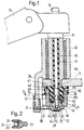
- a wiper lever of which only the wiper arm 10 is indicated in FIG. 1 is.
- This wiper arm is one in the end Wiper shaft 11 attached in a bearing bush 12 is rotatably mounted.
- the wiper shaft will via a suitable gear, to which a swing arm 13 belongs to the at the drive end Wiper shaft 11 is rotatably fixed, oscillating driven.
- Such constructions are adequate known and further explanations are likely therefore unnecessary.
- the connector 20 is overall pot-shaped trained and has a arranged on the bottom 21, radially projecting connecting piece 22 with a feed channel 23 for the washing liquid. From the connector 20 is also a radial fork-like approach 24 with two prongs 25 am End, which is a total of 26 designated Grasp the retaining element, which is axially integral the bearing bush 12 protrudes.
- the connector 20 is axially on the end piece 18 of the washing liquid line 17 attached, one as a leaf spring 30 trained spring element this connector 20 secures in the axial direction. In the embodiment 1 is this leaf spring via a bracket 31 directly on the stationary Holding element 26 fixed and engages centrally on Bottom 21 of the connector 20.
- Fig. 1 the connector 20 tension-free directly at the end piece 18 of the washing liquid line 17 is centered.
- This connector For example, if there is an imbalance in the wiper shaft in all directions in one plane across the wiper shaft at least in one certain dimensions this wobble of the wiper shaft participate. This is because this Connector 20 is not rigid on a stationary Part is fixed, but that the holding means to a certain extent are flexible.
- the anti-rotation device serving elements namely the fork-like approach 24 with the prongs 25 and that Holding element 26 namely leave a balance of conceivable tolerances in one direction radially to axis of symmetry S of wiper shaft and connector 20 to. In this way, one is largely wear free connection between the twist-proof connector 20 and the rotating end piece 18 of the washing liquid line 17 created.
- Fig. 1 From Fig. 1 it can be seen that between the stationary connector 20 and the end piece 18th the washing liquid line 17 a plurality of sealing surfaces are formed. A first sealing surface is created between the bottom of the connector 20 and the support surface 46 at the end piece 18 of the washing liquid line. A second seal is relayed via the O-ring 45. A Of course, sealing also takes place in the area of Bearing surfaces 50 and 51 between the end piece 18 of the washing liquid line 17 and the connector 20. Finally there is a seal through the sealing lip 47 on the radial flange 48 this ensures that even with one high delivery pressure no washing liquid the junction between the connector 20 and the washing liquid channel 17 in the Wiper shaft 11 emerges. It is noted that the greased bearing surfaces 51 on the one hand the sealing ring 45 with respect to the washing liquid and on the other hand also through the sealing lip 47 Dirty water is sealed.
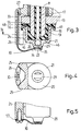
- the exemplary embodiment according to FIG. 3 and 4 differs in education the anti-rotation device by means of a fork-shaped Approach 24 and a holding element 26th not from the exemplary embodiment according to FIGS. 1 and 2. 3, however, that is Spring element 30 as an angled leaf spring trained, one of the inn 33 in one parallel to the meanwhile 11 slot 27 is in the stationary holding element 26 and is locked there.
- the other leg 34 engages again essentially centered on the bottom 21 of the connector 20, again in turn care is taken that this spring element 30 a Movement of the connector 20 in one plane not affected across the wiper shaft.
- To this spring element 30 has a crowned end Elevation 35, which is also crowned Approach 29 on the connector 20 such interacts that one essentially only punctiform plant is given.
- Fig. 5 differs from the embodiment 3 only by another Arrangement of the spring element 30, which in turn is designed as a leaf spring and around a Swiveling on the axis parallel to the wiper shaft End face 57 of the approach or holding element 26 fixed, screwed in the embodiment shown is.
- this tab 58 is the connector in the axial direction on the fixed extension 26 supported.
- this tab 58 has a latch 59, when plugging the connector 20 on the end piece 18 of the washing liquid line 17 behind a stop 60 of a recess snaps into place.
- This can be an additional spring element in the form of a leaf spring.
- This Tab 58 can also prevent rotation be formed, but you can also add Provide holding elements between the tines 25 one in the axial direction from the bearing bush 12 above approach 26 grab.
- Fig. 8 shows an embodiment with a different training of the individual seals.
- O-ring 45 is now not near the bottom 21 of the connector 20, but near the end the wiper shaft 11 arranged.
- Radial flange 56 and on the other hand the ring flange 44 on connector 20 instead of O-ring 55 3 is now a axially projecting sealing lip 62 is provided.
- O-ring 55 3 is now a axially projecting sealing lip 62 is provided.
- the two seals over the O-ring 45 and this sealing lip 62 at a distance from each other arranged so that greased in between Bearing surfaces 50, 51 are formed. It is consciously made sure that the diameter of the O-ring 45 is relatively small, so the axial force acting on it by the pressure of the washing liquid flowing in via the feed channel 23 stays small.
- FIG. 9 and 10 is in place of a leaf spring essential U-shaped wire bracket 65 as a spring element used.
- This wire bracket 65, the Web 66 is fixed to the stationary extension 26, attacks diametrically with his free legs 67 opposite holding pin 68 on the lateral surface of the connector 20.
- Such one Spring element can be manufactured inexpensively and to be assembled.
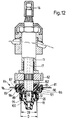
- a substantially square Holding plate 85 On the inside 84 of the gearbox cover 81 is a substantially square Holding plate 85 arranged vertically protruding Holding pin 86, which by appropriate Openings 87 in the gearbox cover 81 protrude through. These holding pins 86 serve as Fasteners for the connector 20 what will be explained later. From the holding plate 85 is also a sleeve 88 from the center the bore 80 in the transmission housing cover 81 enforced. It is important that the diameter DB this socket is smaller than the diameter D of the bore 80 so that the holding plate 85 transversely is slidable to the washing liquid line.
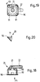
- the connector 20 has an annular flange 90 with receiving holes 91 for the holding pin 86.
- receiving holes 91 for the holding pin 86.
- In the side wall of the connector 20 are Four recesses evenly distributed around the circumference 92 provided with the locking hooks 89 on the Interact holding plate 85.
- the unit consisting of gear and wiper shaft is assembled as follows. First, the holding plate 85 pre-assembled on the gearbox cover 81, the retaining pin 86 through the openings Reach through and then spread them apart again Locking tongues the holding plate 85 hold on gearbox cover 81. On the outside 83 of the gearbox cover then placed a seal 96. Then it will Attachment 20 placed, the holding pin 86 then engage in the receiving holes 91 and the locking hooks 89 in the recesses 92 click into place.
- the socket 88 on the Holding plate 85 directly as a bearing bush for the wiper shaft 11 serves. So that means that too the holding plate 85 is centered on the Wiper shaft 11 or the end piece 18 of the Washer fluid channel 17 is mounted.
- this bearing bush 88 in the pot-like receptacle on the connector 20 protrudes, between the end face 97 this bearing bushing 88 and an approach 98 am Connector 20 is an axially acting sealing element 99 is provided, which has a sealing lip 100, the radial on the En Native 18 of the washing liquid line 17 is present. From the face 97 of the Jack 88 protrudes from a collar 101, this Sealing lip 100 supports so that even at high Operating pressures achieved a perfect sealing effect becomes.
- FIG. 12 also shows that an additional via an O-ring 102 Seal between the holding plate 85 and the Wiper shaft 11 is possible, causing leakage the transmission grease is prevented.
- a check valve 110 can be integrated.
- On an end face 111 of the center of the bottom 21 of the connector 20 protruding and with an axial bore 41 provided approach 40 is a valve seat for a Valve closing member in the form of a ball 114.
- a valve closing spring 115 is supported centrally on an annular shoulder 116 on pipe section 17th and presses the valve closing member 114 on his Valve seat.
- This check valve is in itself a known way of draining the washing liquid line prevented.
Landscapes
- Engineering & Computer Science (AREA)
- Mechanical Engineering (AREA)
- Water Supply & Treatment (AREA)
- Cleaning By Liquid Or Steam (AREA)
- Joints Allowing Movement (AREA)
- Pivots And Pivotal Connections (AREA)
- Sealing Devices (AREA)
Description
- Fig. 1
- in schematischer Darstellung einen Schnitt durch eine Wischerwelle mit einem Anschlußstück,
- Fig. 2
- einen Teilschnitt entlang der Linie II,
- Fig. 3
- einen Teilschnitt eines anderen Ausführungsbeispieles,
- Fig. 4
- einen Teilschnitt entlang der Schnittlinie IV,
- Fig. 5
- einen Teilschnitt eines weiteren Ausführungsbeispieles,
- Fig. 6
- einen Teilschnitt eines weiteren Ausführungsbeispieles,
- Fig. 7
- eine Ansicht in Pfeilrichtung P auf das Ausführungsbeispiel nach Fig.6
- Fig. 8
- einen Teilschnitt durch ein weiteres Ausführungsbeispiel,
- Fig. 9
- eine Ansicht auf ein weiteres Ausführungsbeispiel,
- Fig. 10
- eine Seitenansicht der Ausführung nach Fig. 9.
- Fig. 11
- einen Schnitt durch ein weiteres Ausführungsbeispiel,
- Fig. 12
- einen Schnitt durch ein Ausführungsbeispiel einer aus einem Getriebegehäuse herausragenden Wischerwelle,
- Fig. 13
- eine Ansicht auf den Getriebegehäusedeckel,
- Fig. 14
- in vergrößertem Maßstab einen Schnitt durch ein Anschlußstück,
- Fig. 15
- einen Schnitt durch eine Halteplatte für das Anschlußstück,
- Fig. 16
- eine Ansicht in Pfeilrichtung P auf diese Halteplatte,
- Fig. 17
- einen Haltezapfen dieser Halteplatte,
- Fig. 18
- einen Schnitt durch das Anschlußstück,
- Fig. 19
- eine Ansicht in Pfeilrichtung P1 und
- Fig. 20
- einen Teilschnitt entlang der Schnittlinie XX in Fig. 19.
Claims (38)
- Scheibenreinigungsanlage, insbesondere für Kraftfahrzeuge, mit einer in einer Lagerbuchse (12) drehbar gelagerten Welle (11) zum Antrieb eines Wischhebels, die eine axiale Bohrung (15) zur Aufnahme und/oder Bildung einer Waschflüssigkeitsleitung (17) aufweist, welche während des Betriebes der Scheibenreinigungsanlage mit der Welle (11) pendelt, wobei das Endstück (18) der Waschflüssigkeitsleitung (17) am antriebsseitigen Ende der Welle (11) axial in ein topfförmiges, gegenüber der ortsfesten Lagerbuchse (12) durch eine Verdrehsicherung (24, 25, 26) gesichertes Anschlußstück (20) für einen Waschflüssigkeitszufuhrschlauch hineinragt und Mittel zur axialen Sicherung des Anschlußstückes (20) gegenüber dem Endstück (18) vorgesehen sind und eine Dichtung zwischen dem Endstück (18) der Waschflüssigkeitsleitung (17) und dem Anschlußstück (20) vorgesehen ist, dadurch gekennzeichnet, daß das Anschlußstück (20) in Richtung quer zur Achsrichtung der Welle (11) allein durch das Endstück (18) gehalten ist und daß die Verdrehsicherung (24, 25, 26) einen Ausgleich von Toleranzen in radialer Richtung zuläßt.
- Scheibenreinigungsanlage nach Anspruch 1, dadurch gekennzeichnet, daß zur Verdrehsicherung ein im wesentlichen radial vom Anschlußstück (20) abstehender gabelartiger Ansatz (24) gehört, zwischen dessen Zinken (25) ein ortsfestes, vorzugsweise axial von der Lagerbuchse (12) abstehendes Halteelement (26) passend eingreift.
- Scheibenreinigungsanlage nach Anspruch 1, dadurch gekennzeichnet, daß zur Verdrehsicherung ein im wesentlichen radial vom Anschlußstück (20) abstehendes Halteelement (26) gehört, das passend zwischen die Zinken (25) eines ortsfesten, vorzugsweise axial von der Lagerbuchse (12) abstehenden gabelartigen Ansatzes (24) eingreift.
- Scheibenreinigungsanlage nach Anspruch 1, dadurch gekennzeichnet, daß zur Verdrehsicherung ein im wesentlichen radial vom Anschlußstück (20) abstehendes Haltelement mit wenigstens einem in radialer Richtung federnden Lappen (58) gehört, wobei dieser Lappen (58) mit einem ortsfesten Ansatz (26) verrastet ist.
- Scheibenreinigungsanlage nach Anspruch 4, dadurch gekennzeichnet, daß am Lappen (58) radial eine Rastnase (59) absteht, die beim Aufstecken des Anschlußstuckes (20) auf das Endstück (18) der Waschflüssigkeitsleitung (17) hinter einen Anschlag (60) am ortsfesten Ansatz (26), insbesondere in eine Rastaussparung einrastet.
- Scheibenreinigungsanlage nach wenigstens einem der vorhergehenden Ansprüche, dadurch gekennzeichnet, daß das Anschlußstück (20) über ein in Axialrichtung wirkendes Federelement (30, 65) gegen eine Abstützfläche (46) an dem Endstück (18) der Waschflüssigkeitsleitung (17) angedrückt ist.
- Scheibenreinigungsanlage nach Anspruch 6, dadurch gekennzeichnet, daß das Federelement (30) radial von einem ortsfesten Teil, vorzugsweise von dem der Verdrehsicherung dienenden ortsfesten Ansatz bzw. Halteelement (26), absteht und vorzugsweise zentrisch am Anschlußstück (20) angreift.
- Scheibenreinigungsanlage nach Anspruch 6 oder 7, dadurch gekennzeichnet, daß das Federelement (30) radial in einen Aufnahmeschlitz eines U-förmigen Bügels (31) eingesteckt und dort verrastet ist und daß dieser Bügel (31) selbst über den freien Endbereich eines ortsfesten Ansatzes (26) gesteckt und mit diesem verrastet ist.
- Scheibenreinigungsanlage nach Anspruch 6 oder 7, dadurch gekennzeichnet, daß das Federelement (30) um eine Achse parallel zur Wischerwelle (11) schwenkbar an der Stirnfläche (57) eines ortsfesten Ansatzes (26) fixiert, vorzugsweise verschraubt ist.
- Scheibenreinigungsanlage nach den Ansprüchen 6 bis 9, dadurch gekennzeichnet, daß das Federelement als Blattfeder (30) oder als Drahtbügel (65) ausgebildet ist.
- Scheibenreinigungsanlage nach Anspruch 6 oder 7, dadurch gekennzeichnet, daß das Federelement als winklig abgebogene Blattfeder (30) ausgebildet ist, dessen einer Schenkel (33) in einem parallel zur Wischerwelle (11) verlaufenden Schlitz (27) in einer ortsfesten Ansatz (26) eingesteckt und dort verrastet ist.
- Scheibenreinigungsanlage nach wenigstens einem der Ansprüche 6 bis 11, dadurch gekennzeichnet, daß die Blattfeder (30) nahe ihrem freien Ende eine Rasteinbuchtung (32) oder Rasterhebung (35) aufweist und mit einem zugehörig ausgebildeten zentrisch an Boden des Anschlußstückes (20) angeordneten Ansatz (29) zusammenwirkt.
- Scheibenreinigungsanlage nach Anspruch 6 oder 7, dadurch gekennzeichnet, daß das Federelement ein U-förmiger Drahtbügel (65) ist, dessen Steg (66) an einem ortsfesten Ansatz (26) fixiert ist und dessen freie Schenkel (67) an diametral gegenüberliegenden Haltezapfen (68) an der Mantelfläche des Anschlußstückes (20) anliegen.
- Scheibenreinigungsanlage nach wenigstens einem der Ansprüche 6 bis 13, dadurch gekennzeichnet, daß auch das Federelement (30,65) eine Radialbewegung des Anschlußstückes (20) in gewissem Umfang zuläßt.
- Scheibenreinigungsanlage nach wenigstens einem der vorhergehenden Ansprüche, dadurch gekennzeichnet, daß nahe dem Boden (21) des Anschlußstückes (20) zwischen der äußeren Mantelfläche des Endstückes (18) der Waschflüssigkeitsleitung (17) und der inneren Mantelfläche des Anschlußstückes (20) eine Radialdichtung vorzugsweise durch einen O-Ring (45) realisiert ist.
- Scheibenreinigungsanlage nach Anspruch 15, dadurch gekennzeichnet, daß in axialem Abstand von dieser Radialdichtung eine weitere Dichtung zwischen dem Anschlußstück (20) und dem Endstück der Waschflüssigkeitsleitung (17) vorgesehen ist und daß zwischen diesen beiden Dichtungen eine vorzugsweise gefettete Lagerfläche (51) zwischen dem Endstück (18) der Waschflüssigkeitsleitung (17) und dem Anschlußstück (20) vorgesehen ist.
- Scheibenreinigungsanlage nach Anspruch 16, dadurch gekennzeichnet, daß von der Stirnfläche des Anschlußstückes (20) axial eine Dichtlippe (47) absteht, die an einem Radialflansch (48) an der Waschflüssigkeitsleitung (17) dichtend anliegt.
- Scheibenreinigungsanlage nach Anspruch 16, dadurch gekennzeichnet, daß in einer Nut in der Stirnfläche des Anschlußstückes (20) ein Dichtring (55) angeordnet ist, der an einem Radialflansch (48) an der Waschflüssigkeitsleitung (17) dichtend anliegt.
- Scheibenreinigungsanlage nach Anspruch 17 oder 18, dadurch gekennzeichnet, daß von dem Radialflansch (48) axial ein die Dichtlippe (47) bzw. den Dichtring (55) übergreifender Ringflansch (49) absteht.
- Scheibenreinigungsanlage nach Anspruch 16, dadurch gekennzeichnet, daß die Stirnfläche des Anschlußstückes (20) in eine Dichtlippe (61) ausläuft, die radial an der äußeren Mantelfläche des Waschflüssigkeitskanals oder der Wischerwelle (11) anliegt.
- Scheibenreinigungsanlage nach wenigstens einem der Ansprüche 1 bis 14, dadurch gekennzeichnet, daß vom Boden (21) des topfförmigen Anschlußstückes (20) zentrisch ein zylindrischer Ansatz (40) ausgeht, der eine Bohrung (41) als Waschflüssigkeitskanal aufweist, daß zwischen diesem zylindrischen Ansatz (40) und der Seitenwand des Anschlußstückes (20) ein Ringraum (43) gebildet ist, in den ein axial von der Waschflüssigkeitsleiteung (17) abstehender Ringflansch (44) passend eingreift und daß zwischen diessem Ringflansch (44) und dem zylindrischen Ansatz (40) nahe dessen freiem Ende eine Radialdichtung vorzugsweis ein Form eines O-Ringes (45) realisiert ist.
- Scheibenreinigungsanlage nach Anspruch 21, dadurch gekennzeichnet, daß das Anschlußstück (20) einen Flansch (44) mit einer axialen Anlauffläche an einem zugehörigen Flansch (56) an der Waschflüssigkeitsleitung (17) aufweist und daß zwischen diesen beiden Flanschen eine Dichtung vorzugsweise in Form einer Ringlippe (62) realisiert ist.
- Scheibenreinigungsanlage nach wenigstens einem der vorhergehenden Ansprüche, dadurch gekennzeichnet, daß das Endstück (18) der Waschflüssigkeitsleitung (17) zu einem in die Bohrung der Wischerwelle (11) eingesetzten oder eingespritzten Rohrstück (17) gehört.
- Scheibenreinigungsanlage nach Anspruch 23, dadurch gekennzeichnet, daß die Seitenwand des Anschlußstückes (20) über das Endstück (18) dieses Rohrstückes (17) und einen Teilbereich der Wischerwelle (11) gestülpt ist.
- Scheibenreinigungsanlage nach Anspruch 23, dadurch gekennzeichnet, daß das Endstück (18) des Rohrstückes (17) den Endbereich der Wischerwelle (11) topfartig umgibt und das Anschlußstück (20) lediglich über die Außenwand des Endstückes (18) des Rohrstückes (17) gestülptist.
- Scheibenreinigungsanlage nach Anspruch 23, dadurch gekennzeichnet, daß das Anschlußstück (20) über das aus der Wischerwelle (11) vorstehende Endstück (18) des Rohrstückes (17) gestülpt ist und mit einer einstückig angeformten Dichtlippe (61) am Endbereich der Mantelfläche der Wischerwelle (11) anliegt.
- Scheibenreinigungsanlage nach wenigstens einem der vorhergehenden Ansprüche, dadurch gekennzeichnet, daß in das Anschlußstück (20) ein Ventil, vorzugsweise ein Rückschlagventil (110) integriert ist.
- Scheibenreinigungsanlage nach Anspruch 27, dadurch gekennzeichnet, daß an der Stirnfläche (111) eines zentrisch vom Boden (21) des Anschlußstückes (20) abstehenden, mit einer Axialbohrung (41) versehenen zylindrischen Ansatzes (40) der Ventilsitz für ein Ventilschließglied, vorzugweise eine Kugel (114) ausgebildet ist, und daß sich eine Ventilschließfeder (115) an einer Ringschulter (116) zentrisch zum Rohrstück (17) abstützt, die das Ventilschließglied (114) auf seinen Ventilsitz drückt.
- Scheibenreinigungsanlage nach Anspruch 1, dadurch gekennzeichnet, daß das Endstück (18) der Waschflüssigkeitsleitung (17) durch eine Bohrung (80) eines ein Getriebegehäuse abschließenden Deckels (81) hindurchragt und das Anschlußstück (20) auf der dem Getriebe abgewandten Außenseite (83) des Deckels (81) verschiebbar befestigt ist.
- Scheibenreinigungsanlage nach Anspruch 29, dadurch gekennzeichnet, daß auf der Innenseite (84) des Deckels (81) eine Halteplatte (85) verschiebbar festgelegt ist, die durch den Deckel (81) hindurchragende Befestigungsmittel (86,89) aufweist, an denen das Anschlußstück (20) befestigt ist.
- Scheibenreinigungsanlage nach Anspruch 30, dadurch gekennzeichnet, daß die Befestigungsmittel (86,89) als Rastmittel derart ausgebildet sind, daß nach dem Aufrasten des Anschlußstückes (20) die Halteplatte (85) auf der einen Seite und das Anschlußstück (20) auf der anderen Seite - gegebenfalls unter Zwischenlage eines Dichtringes - mit geringer Spannung am Deckel (81) des Getriebegehäuses anlegen.
- Scheibenreinigungsanlage nach Anspruch 30 oder 31, dadurch gekennzeichnet, daß die Halteplatte (85) eine Buchse (88) aufweist, die eine Bohrung (80) am Deckel (81) durchdringt, wobei der Außendurchmesser (DB) der Buchse (88) kleiner ist als der Durchmesser (D) der Bohrung (80), und daß von der Außenseite der Buchse (88) Rasthaken (89) abstehen, die hinter einen Flansch am Anschlußstück (20) greifen.
- Scheibenreinigungsanlage nach Anspruch 32, dadurch gekennzeichnet, daß diese Buchse (88) als Lagerbuchse für die Wischerwelle (11) dient.
- Scheibenreinigungsanlage nach einem der Ansprüche 30 bis 33, dadurch gekennzeichnet, daß an der Halteplatte (85) mehrere Haltezapfen (86) als Befestigungsmittel vorhanden sind, die jeweils mit seitlichem Spiel durch entsprechende Durchbrüche (87) im Deckel (81) hindurchragen, und daß diese Haltezapfen (86) in Aufnahmelöcher (91) in einem Flansch (92) des Anschlußstückes (20) einrastbar sind.
- Scheibenreinigungsanlage nach Anspruch 32 oder 33, dadurch gekennzeichnet, daß die Lagerbuchse (88) in eine topfartige Aufnahme am Anschlußstück (20) hineinragt und zwischen der Stirnfläche (97) der Lagerbuchse (88) und einem Ansatz (98) am Anschlußstück (20) ein axial wirkendes Dichtelement (99) vorgesehen ist.
- Scheibenreinigungsanlage nach Anspruch 35, dadurch gekennzeichnet, daß das Dichtelement (99) außerdem eine Dichtlippe (100) aufweist, die radial absteht und dichtend am Endstück (18) der Waschflüssigkeitsleitung (17) anliegt.
- Scheibenreinigungsanlage nach Anspruch 36, dadurch gekennzeichnet, daß von der Stirnfläche (97) der Lagerbuchse (88) ein Kragen (101) absteht, der die Dichtlippe (100) axial unterstützt.
- Scheibenreinigungsanlage nach einem der Ansprüche 30 bis 37, dadurch gekennzeichnet, daß das Anschlußstück (20) einen Lagerbereich für das Endstück (18) der Waschflüssigkeitsleitung (17) aufweist.
Applications Claiming Priority (3)
| Application Number | Priority Date | Filing Date | Title |
|---|---|---|---|
| DE3907962 | 1989-03-11 | ||
| DE19893907962 DE3907962C2 (de) | 1989-03-11 | 1989-03-11 | Scheibenreinigungsanlage, insbesondere für Kraftfahrzeuge |
| PCT/EP1990/000345 WO1990010562A1 (de) | 1989-03-11 | 1990-03-02 | Scheibenreinigungsanlage, insbesondere für kraftfahrzeuge |
Publications (3)
| Publication Number | Publication Date |
|---|---|
| EP0414873A1 EP0414873A1 (de) | 1991-03-06 |
| EP0414873B1 EP0414873B1 (de) | 1994-06-01 |
| EP0414873B2 true EP0414873B2 (de) | 1999-03-03 |
Family
ID=6376131
Family Applications (1)
| Application Number | Title | Priority Date | Filing Date |
|---|---|---|---|
| EP19900904304 Expired - Lifetime EP0414873B2 (de) | 1989-03-11 | 1990-03-02 | Scheibenreinigungsanlage, insbesondere für kraftfahrzeuge |
Country Status (7)
| Country | Link |
|---|---|
| US (1) | US5195206A (de) |
| EP (1) | EP0414873B2 (de) |
| JP (1) | JPH03504589A (de) |
| BR (1) | BR9005771A (de) |
| DE (1) | DE3907962C2 (de) |
| ES (1) | ES2054345T5 (de) |
| WO (1) | WO1990010562A1 (de) |
Cited By (1)
| Publication number | Priority date | Publication date | Assignee | Title |
|---|---|---|---|---|
| DE102004014078A1 (de) * | 2004-03-23 | 2005-10-13 | Valeo Wischersysteme Gmbh | Scheibenwischeranlage |
Families Citing this family (14)
| Publication number | Priority date | Publication date | Assignee | Title |
|---|---|---|---|---|
| FR2674489B1 (fr) * | 1991-03-29 | 1995-08-04 | Valeo Systemes Dessuyage | Dispositif de lave-glace, notamment pour vehicule automobile. |
| DE4117107B4 (de) * | 1991-05-25 | 2006-02-16 | Itt Automotive Europe Gmbh | Scheibenreinigungsanlage, insbesondere für Kraftfahrzeuge |
| FR2722463B1 (fr) * | 1994-07-13 | 1996-08-23 | Valeo Systemes D Essuyage Sa | Dispositif de lave-glace, notamment pour vehicule automobile |
| FR2762273B1 (fr) * | 1997-04-22 | 1999-07-02 | Valeo Systemes Dessuyage | Motoreducteur pour essuie-glace de vehicule automobile avec un conduit de liquide de nettoyage |
| DE19946632A1 (de) * | 1999-09-29 | 2001-04-05 | Volkswagen Ag | Scheibenwischeranlage für ein Fahrzeug |
| DE19946631A1 (de) * | 1999-09-29 | 2001-04-05 | Volkswagen Ag | Scheibenwischeranlage für Fahrzeuge |
| DE10209418B4 (de) * | 2002-03-05 | 2016-02-11 | Continental Automotive Gmbh | Reinigungsvorrichtung zur Reinigung einer Scheibe eines Kraftfahrzeuges |
| CN101331354A (zh) * | 2005-12-16 | 2008-12-24 | 卡尔·赖纳有限责任公司 | 用于与管状件连接的连接元件 |
| DE102009051021A1 (de) | 2009-10-28 | 2011-05-05 | Valeo Wischersysteme Gmbh | Wischwelle für Scheibenwischanlagen von Fahrzeugen sowie Scheibenwischanlage mit einer solchen Wischwelle |
| DE102012222038B4 (de) | 2012-12-03 | 2025-02-06 | Continental Automotive Technologies GmbH | Hydraulisches Reinigungssystem |
| KR101417490B1 (ko) * | 2012-12-18 | 2014-07-08 | 현대자동차주식회사 | 자동차용 워셔액 공급 장치 |
| FR3003219B1 (fr) * | 2013-03-14 | 2016-11-18 | Valeo Systemes Dessuyage | Dispositif de distribution de liquide lave-glace de balais d'essuie-glace de vehicule automobile |
| JP6257341B2 (ja) * | 2014-01-16 | 2018-01-10 | 株式会社ミツバ | ノズルおよびその製造方法並びにウォッシャノズル |
| JP2016088319A (ja) * | 2014-11-06 | 2016-05-23 | 株式会社ミツバ | ワイパモータ |
Family Cites Families (16)
| Publication number | Priority date | Publication date | Assignee | Title |
|---|---|---|---|---|
| US933290A (en) * | 1908-08-31 | 1909-09-07 | William J Clay | Reel-operated hydrant. |
| US2483243A (en) * | 1944-02-11 | 1949-09-27 | Productive Inventions Inc | Fluid transmission connection for cleaner wipers |
| US2679434A (en) * | 1951-05-31 | 1954-05-25 | Vineent M Idziak | Safety reel with automatic valve |
| US3129960A (en) * | 1959-10-01 | 1964-04-21 | Reimers Getriebe Kg | Device for feeding pressure fluids from a stationary bearing cover into the outer end of a rotating shaft |
| US3591206A (en) * | 1969-04-01 | 1971-07-06 | Paul S Giovagnoli | Rotary water distributor for rotatable spray assembly |
| US3760451A (en) * | 1971-11-30 | 1973-09-25 | M Steed | Combination windshield wiper and washer |
| US3887956A (en) * | 1973-10-18 | 1975-06-10 | Lescoa Inc | Windshield wiper fluid dispenser |
| US4313624A (en) * | 1980-06-06 | 1982-02-02 | Zierden Company | Swivel cartridge |
| DE8100709U1 (de) * | 1981-01-15 | 1982-07-01 | Robert Bosch Gmbh, 7000 Stuttgart | Reinigungsvorrichtung fuer scheiben von kraftfahrzeugen |
| DE3102538C1 (de) * | 1981-01-27 | 1982-11-11 | Ford-Werke AG, 5000 Köln | Scheibenwischerarm mit Wascherduese fuer Kraftfahrzeugscheiben |
| JPS57194140A (en) * | 1981-05-25 | 1982-11-29 | Mazda Motor Corp | Wind washer for car |
| DE3521024C2 (de) * | 1984-06-20 | 1994-12-08 | Volkswagen Ag | Scheibenreinigungsvorrichtung für Fahrzeuge |
| JPS61247543A (ja) * | 1985-04-05 | 1986-11-04 | Takeo Isaka | ウインド洗滌液噴出機構を有するワイパ−ア−ム作動軸ボルトに装着する流体継手 |
| DE3523441A1 (de) * | 1985-06-29 | 1987-01-08 | Swf Auto Electric Gmbh | Scheibenwischeranlage |
| DE3632734A1 (de) * | 1986-09-26 | 1988-03-31 | Swf Auto Electric Gmbh | Scheibenreinigungsanlage, insbesondere fuer kraftfahrzeuge |
| DE3643476A1 (de) * | 1986-12-19 | 1988-06-30 | Swf Auto Electric Gmbh | Scheibenreinigungsanlage |
-
1989
- 1989-03-11 DE DE19893907962 patent/DE3907962C2/de not_active Expired - Lifetime
-
1990
- 1990-03-02 US US07/623,375 patent/US5195206A/en not_active Expired - Lifetime
- 1990-03-02 ES ES90904304T patent/ES2054345T5/es not_active Expired - Lifetime
- 1990-03-02 JP JP2504171A patent/JPH03504589A/ja active Pending
- 1990-03-02 EP EP19900904304 patent/EP0414873B2/de not_active Expired - Lifetime
- 1990-03-02 BR BR9005771A patent/BR9005771A/pt not_active IP Right Cessation
- 1990-03-02 WO PCT/EP1990/000345 patent/WO1990010562A1/de not_active Ceased
Cited By (2)
| Publication number | Priority date | Publication date | Assignee | Title |
|---|---|---|---|---|
| DE102004014078A1 (de) * | 2004-03-23 | 2005-10-13 | Valeo Wischersysteme Gmbh | Scheibenwischeranlage |
| DE102004014078B4 (de) * | 2004-03-23 | 2021-01-14 | Valeo Wischersysteme Gmbh | Scheibenwischeranlage |
Also Published As
| Publication number | Publication date |
|---|---|
| WO1990010562A1 (de) | 1990-09-20 |
| EP0414873B1 (de) | 1994-06-01 |
| DE3907962C2 (de) | 1998-07-09 |
| ES2054345T3 (es) | 1994-08-01 |
| US5195206A (en) | 1993-03-23 |
| EP0414873A1 (de) | 1991-03-06 |
| BR9005771A (pt) | 1991-08-06 |
| DE3907962A1 (de) | 1990-09-13 |
| ES2054345T5 (es) | 1999-07-01 |
| JPH03504589A (ja) | 1991-10-09 |
Similar Documents
| Publication | Publication Date | Title |
|---|---|---|
| EP0414873B1 (de) | Scheibenreinigungsanlage, insbesondere für kraftfahrzeuge | |
| EP0500868B1 (de) | Antriebsvorrichtung, insbesondere für scheibenwischer an kraftfahrzeugen | |
| EP0557602B1 (de) | Vielzweckküchenmaschine zum Bearbeiten von Nahrungsmitteln | |
| DE4409957B4 (de) | Lagervorrichtung für eine Welle oder Achse, insbesondere für eine Scheibenwischeranlage | |
| DE19804135B4 (de) | Wischerlager | |
| DE3732069A1 (de) | Scheibenwischer mit verstellbarem schwenkwinkelbereich des wischerarms | |
| DE112011103771B4 (de) | Schwenkkörper für Frontscheibenwischeranlage | |
| EP1718507B1 (de) | Scheibenwischanlage für fahrzeuge sowie befestigungselement für eine solche anlage | |
| EP1539546A1 (de) | Lagerung f r wischerantriebe | |
| EP0443662B1 (de) | Sprüharmlagerung bei einer Geschirrspülmaschine | |
| EP0549754A1 (de) | Elektromotor, insbesondere für eine scheibenwischanlage eines kraftfahrzeugs | |
| DE10331854B4 (de) | Korrosionsgeschütztes Wischerwellenlager | |
| DE2622437A1 (de) | Wischvorrichtung fuer scheiben von kraftfahrzeugen | |
| DE3907967A1 (de) | Scheibenreinigungsanlage | |
| DE3632734A1 (de) | Scheibenreinigungsanlage, insbesondere fuer kraftfahrzeuge | |
| EP0864472B1 (de) | Antriebsvorrichtung, insbesondere für Scheibenwischer an Kraftfahrzeugen | |
| DE69306159T2 (de) | Scheibenwaschanlage, insbesondere für Kraftfahrzeugscheibenoberfläche | |
| WO2007141127A1 (de) | Getriebe-antriebseinheit mit einem mitnehmer, insbesondere zum verstellen beweglicher teile im kraftfahrzeug | |
| DE19521084B4 (de) | Wischerwelle für eine Scheibenwischeranlage, insbesondere eines Kraftfahrzeuges | |
| EP1480857A1 (de) | Wischeranlage mit einer platine | |
| DE102004014078B4 (de) | Scheibenwischeranlage | |
| DE10309942B4 (de) | Scheibenwischer-Vorrichtung | |
| DE19542875A1 (de) | Wischerlager einer Scheibenwischvorrichtung eines Fahrzeuges | |
| DE69202501T2 (de) | Scheibenwaschanlage, insbesondere für Kraftfahrzeugscheibenoberfläche. | |
| DE19953482B4 (de) | Scheibenwischeranlage für ein Fahrzeug |
Legal Events
| Date | Code | Title | Description |
|---|---|---|---|
| PUAI | Public reference made under article 153(3) epc to a published international application that has entered the european phase |
Free format text: ORIGINAL CODE: 0009012 |
|
| 17P | Request for examination filed |
Effective date: 19901113 |
|
| AK | Designated contracting states |
Kind code of ref document: A1 Designated state(s): ES FR GB IT SE |
|
| 17Q | First examination report despatched |
Effective date: 19921215 |
|
| ITF | It: translation for a ep patent filed | ||
| GRAA | (expected) grant |
Free format text: ORIGINAL CODE: 0009210 |
|
| RAP1 | Party data changed (applicant data changed or rights of an application transferred) |
Owner name: ITT AUTOMOTIVE EUROPE GMBH |
|
| AK | Designated contracting states |
Kind code of ref document: B1 Designated state(s): ES FR GB IT SE |
|
| GBT | Gb: translation of ep patent filed (gb section 77(6)(a)/1977) |
Effective date: 19940609 |
|
| REG | Reference to a national code |
Ref country code: ES Ref legal event code: FG2A Ref document number: 2054345 Country of ref document: ES Kind code of ref document: T3 |
|
| ET | Fr: translation filed | ||
| EAL | Se: european patent in force in sweden |
Ref document number: 90904304.4 |
|
| PLBI | Opposition filed |
Free format text: ORIGINAL CODE: 0009260 |
|
| 26 | Opposition filed |
Opponent name: VALEO SYSTEMES D'ESSUYAGE Effective date: 19950301 |
|
| PLBQ | Unpublished change to opponent data |
Free format text: ORIGINAL CODE: EPIDOS OPPO |
|
| PLAB | Opposition data, opponent's data or that of the opponent's representative modified |
Free format text: ORIGINAL CODE: 0009299OPPO |
|
| R26 | Opposition filed (corrected) |
Opponent name: VALEO SYSTEMES D'ESSUYAGE Effective date: 19950301 |
|
| PLAW | Interlocutory decision in opposition |
Free format text: ORIGINAL CODE: EPIDOS IDOP |
|
| APAE | Appeal reference modified |
Free format text: ORIGINAL CODE: EPIDOS REFNO |
|
| APAC | Appeal dossier modified |
Free format text: ORIGINAL CODE: EPIDOS NOAPO |
|
| APAC | Appeal dossier modified |
Free format text: ORIGINAL CODE: EPIDOS NOAPO |
|
| PGFP | Annual fee paid to national office [announced via postgrant information from national office to epo] |
Ref country code: GB Payment date: 19970221 Year of fee payment: 8 |
|
| PG25 | Lapsed in a contracting state [announced via postgrant information from national office to epo] |
Ref country code: GB Free format text: LAPSE BECAUSE OF NON-PAYMENT OF DUE FEES Effective date: 19980302 |
|
| APAC | Appeal dossier modified |
Free format text: ORIGINAL CODE: EPIDOS NOAPO |
|
| PLAW | Interlocutory decision in opposition |
Free format text: ORIGINAL CODE: EPIDOS IDOP |
|
| GBPC | Gb: european patent ceased through non-payment of renewal fee |
Effective date: 19980302 |
|
| PUAH | Patent maintained in amended form |
Free format text: ORIGINAL CODE: 0009272 |
|
| STAA | Information on the status of an ep patent application or granted ep patent |
Free format text: STATUS: PATENT MAINTAINED AS AMENDED |
|
| 27A | Patent maintained in amended form |
Effective date: 19990303 |
|
| AK | Designated contracting states |
Kind code of ref document: B2 Designated state(s): ES FR GB IT SE |
|
| PGFP | Annual fee paid to national office [announced via postgrant information from national office to epo] |
Ref country code: SE Payment date: 19990326 Year of fee payment: 10 |
|
| ET3 | Fr: translation filed ** decision concerning opposition | ||
| ITF | It: translation for a ep patent filed | ||
| REG | Reference to a national code |
Ref country code: ES Ref legal event code: DC2A Kind code of ref document: T5 Effective date: 19990429 |
|
| PG25 | Lapsed in a contracting state [announced via postgrant information from national office to epo] |
Ref country code: SE Free format text: LAPSE BECAUSE OF NON-PAYMENT OF DUE FEES Effective date: 20000303 |
|
| EUG | Se: european patent has lapsed |
Ref document number: 90904304.4 |
|
| APAH | Appeal reference modified |
Free format text: ORIGINAL CODE: EPIDOSCREFNO |
|
| PGFP | Annual fee paid to national office [announced via postgrant information from national office to epo] |
Ref country code: ES Payment date: 20090323 Year of fee payment: 20 |
|
| PGFP | Annual fee paid to national office [announced via postgrant information from national office to epo] |
Ref country code: FR Payment date: 20090331 Year of fee payment: 20 Ref country code: IT Payment date: 20090319 Year of fee payment: 20 |
|
| REG | Reference to a national code |
Ref country code: ES Ref legal event code: FD2A Effective date: 20100303 |
|
| PG25 | Lapsed in a contracting state [announced via postgrant information from national office to epo] |
Ref country code: ES Free format text: LAPSE BECAUSE OF EXPIRATION OF PROTECTION Effective date: 20100303 |