US5195206A - Windshield cleaning system, especially for motor vehicles - Google Patents
Windshield cleaning system, especially for motor vehicles Download PDFInfo
- Publication number
- US5195206A US5195206A US07/623,375 US62337590A US5195206A US 5195206 A US5195206 A US 5195206A US 62337590 A US62337590 A US 62337590A US 5195206 A US5195206 A US 5195206A
- Authority
- US
- United States
- Prior art keywords
- connecting piece
- washing liquid
- cleaning system
- windshield cleaning
- liquid pipe
- Prior art date
- Legal status (The legal status is an assumption and is not a legal conclusion. Google has not performed a legal analysis and makes no representation as to the accuracy of the status listed.)
- Expired - Lifetime
Links
Images




Classifications
-
- B—PERFORMING OPERATIONS; TRANSPORTING
- B60—VEHICLES IN GENERAL
- B60S—SERVICING, CLEANING, REPAIRING, SUPPORTING, LIFTING, OR MANOEUVRING OF VEHICLES, NOT OTHERWISE PROVIDED FOR
- B60S1/00—Cleaning of vehicles
- B60S1/02—Cleaning windscreens, windows or optical devices
- B60S1/46—Cleaning windscreens, windows or optical devices using liquid; Windscreen washers
- B60S1/48—Liquid supply therefor
- B60S1/52—Arrangement of nozzles; Liquid spreading means
- B60S1/522—Arrangement of nozzles; Liquid spreading means moving liquid spreading means, e.g. arranged in wiper arms
-
- B—PERFORMING OPERATIONS; TRANSPORTING
- B60—VEHICLES IN GENERAL
- B60S—SERVICING, CLEANING, REPAIRING, SUPPORTING, LIFTING, OR MANOEUVRING OF VEHICLES, NOT OTHERWISE PROVIDED FOR
- B60S1/00—Cleaning of vehicles
- B60S1/02—Cleaning windscreens, windows or optical devices
- B60S1/04—Wipers or the like, e.g. scrapers
- B60S1/32—Wipers or the like, e.g. scrapers characterised by constructional features of wiper blade arms or blades
- B60S1/34—Wiper arms; Mountings therefor
- B60S1/3415—Wiper arms; Mountings therefor with means for supplying cleaning fluid to windscreen cleaners, e.g. washers
-
- Y—GENERAL TAGGING OF NEW TECHNOLOGICAL DEVELOPMENTS; GENERAL TAGGING OF CROSS-SECTIONAL TECHNOLOGIES SPANNING OVER SEVERAL SECTIONS OF THE IPC; TECHNICAL SUBJECTS COVERED BY FORMER USPC CROSS-REFERENCE ART COLLECTIONS [XRACs] AND DIGESTS
- Y10—TECHNICAL SUBJECTS COVERED BY FORMER USPC
- Y10T—TECHNICAL SUBJECTS COVERED BY FORMER US CLASSIFICATION
- Y10T137/00—Fluid handling
- Y10T137/8593—Systems
- Y10T137/86268—With running joint between movable parts of system
Definitions
- the invention relates to a windshield cleaning system, especially for motor vehicles.
- Windshield cleaning systems in which the washing liquid is supplied to jets for the purpose of improving the effect of the washing system, which jets are arranged on the wiper arm-and-blade assembly and are moving to and fro with it, are already known.
- the washing liquid is supplied through a pipe within a bore in a wiper shaft, whereby the end of the washing liquid pipe at the drive end of the wiper shaft axially engages into a pot-like connecting piece from which a tube stud for connecting a washing liquid supply tube is sticking out.
- the washing liquid pipe is moving to and fro like the wiper shaft, whereas the connecting piece is non-rotatably fixed because otherwise, the washing liquid supply tube would considerably be strained during operation of the cleaning system and there would be danger of tearing off after a longer time of operation.
- the connecting piece is fixed onto a frame via an extension arm radially sticking out. In both cases not only a protection against twisting is realized by this extension arm, but also the connecting piece is rigidly fixed onto a stationary member.
- the object of the present invention is to develop such a windshield cleaning system by using easy means in such a way that operation, especially perfect seal and bearing without play is guaranteed even after a longer time of operation.
- One aspect of the invention is based on the idea that, when the connecting piece is resilently centered with respect to the end of the washing liquid pipe, the eccentric movement or the balance error of the wiper shaft, which cannot be excluded after some time of operation, does not negatively affect the seal between the connecting piece and the end because the connecting piece can also make this movement caused by balance error.
- the connecting piece is flexibly mounted.
- the resilient centering can also be described in such a way that the connecting piece is held in a plane cross-wise to the axial direction of the shaft only by means of the end so that with respect to the stationary member only one security preventing the connecting piece from twisting is necessary.
- no radial forces are exerted onto the bearing point so that there is no danger of early wear.
- the protection against twisting comprises a fork-like stud sticking out of the connecting piece, between the tines of which stud a stationary holding element engages, it should be possible to swivel this fork-like stud around the holding element to a certain extent. This can be achieved in a very simple way by forming this holding element as a round rod.
- the resilient element necessary for this purpose is fixed onto the stationary element which, as a part of the protection against twisting, is necessary anyway.
- this resilient element is formed in such a way that a radial movement of the connecting piece is permitted so that the braceless centration of said connecting piece with respect to the end of the washing liquid pipe is not reduced.
- the basic ideas of the invention can be realized in windshield cleaning systems in which the drive motor with the gear is arranged separately from the wiper bearing. Systems of this kind are normally used for cleaning windshields in motor vehicles.
- the basic ideas of the present invention can also be realized in a wiper system, for instance for rear windows or headlights, in which the wiper motor with the gear and the wiper shaft are arranged in one housing. In this case the washing water has to be delivered through the motor or the gear housing and to be supplied to the jet through the washing liquid pipe inside the wiper shaft.
- the connecting piece is to be centered bracelessly concerning the end of the washing liquid pipe so that too much wear is avoided.
- the end of the washing liquid pipe is to penetrate a bore of the lid of the gear housing, whereby the connecting piece is movably fixed--cross-wise to the washing liquid pipe onto the outer side of the lid turning away from the gear.
- the lid of the gear housing need not perfectly be centered in relation to the wiper shaft, and in addition, the advantage of such a solution is that the connecting piece with the seals lying therein can easily be changed in case of failure.
- Other advantageous developments of the invention are characterized, which developments refer to a seal of the bore that can easily be assembled.
- the holding plate provided for this purpose comprises a bush which simultaneously serves as a bearing bush for the wiper shaft.
- the connecting piece is formed of two parts, whereby the lid of the gear housing is located between the two parts as soon as these two parts are locked within each other.
- Still other aspects of the invention refer to special features concerning the seal between the connecting piece and the end of the washing liquid channel, which features ensure a long lifetime.
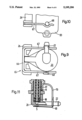
- FIG. 1 is a schemematic view of a section of a wiper shaft with a connecting piece
- FIG. 2 is a partial section taken along the line II of FIG. 1;
- FIG. 3 is a partial section of another embodiment
- FIG. 4 is a partial section taken along the line IV of FIG. 3;
- FIG. 5, is a partial section of another embodiment
- FIG. 6, is a partial section of another embodiment
- FIG. 7 is a view in the direction of arrow P of the embodiment according to FIG. 6;
- FIG. 8 is a partial section of another embodiment
- FIG. 9, is a view of another embodiment
- FIG. 10 is a lateral view of the embodiment according to FIG. 9;
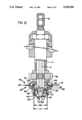
- FIG. 11, is a section of another embodiment
- FIG. 12 is a section of an embodiment of a wiper shaft extending a gear housing
- FIG. 13 is a view of the lid of the gear housing
- FIG. 14 is an enlarged section of a connecting piece
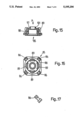
- FIG. 15 is a section of a holding plate for the connecting piece
- FIG. 16 is a view in the direction of arrow P of the holding plate of FIG. 15;
- FIG. 17, is a holding pin of the holding plate
- FIG. 18, is a section of the connecting piece
- FIG. 19 is a view in the direction of arrow P1 of FIG. 18.
- FIG. 20, is a partial section taken along the line XX in FIG. 19.
- a windshield cleaning system of a motor vehicle comprises a wiper arm-and-blade assembly, only the wiper arm 10 of which is indicated in FIG. 1.
- the wiper arm is fixed onto the end of a wiper shaft 11, which is rotatably mounted in a bearing bush 12.
- the wiper shaft is driven in pendulum-motion via a suitable gear comprising a swivelling lever 13 which is non-rotatably fixed onto the drive end on the wiper shaft 11. Constructions of this sort are well known and therefore no further explanations will be necessary.
- the windshield cleaning systems of modern motor vehicles comprise a washing system via which the washing liquid is sprayed onto the windshield to be cleaned.
- washing liquid is supplied to a jet 16 through an axial bore 15 in the wiper shaft.
- Either the axial bore 15 in the wiper shaft 11 or a pipe portion 17 can serve as the washing liquid pipe, which pipe portion 17 is inserted or is directly injection-moulded into bore 15.
- the jet 16 terminates the one end of pipe portion 17. Normally this does not cause any problems because at this point there is no relative movement between the two parts to be connected, that is, between the jet 16 and the pipe portion 17.
- the connecting piece 20 is generally formed like a pot and has a connecting stud 22 with a supply channel 23 for the washing liquid, which connecting stud 22 is arranged on the bottom 21 and is radially sticking out of it. Furthermore a fork-like stud 24 with two tines 25 at the end are radially sticking out of the connecting piece 20, which tines 25 grip a holding element generally designated by 26 and integrally axially sticking out of the bearing bush 12.
- the connecting piece 20 is axially put onto the end 18 of the washing liquid pipe 17, whereby a resilient element formed as a leaf spring 30 secures connecting piece 20 in axial direction.
- leaf spring 30 is fixed directly on the stationary holding element 26 by means of a clamp 31 and centrically acts upon the bottom 21 of the connecting piece 20.
- the connecting piece 20 is bracelessly centered immediately at the end 18 of the washing liquid pipe.
- this connecting piece can also make a wobbling movement of the wiper shaft in a plane cross-wise to the wiper shaft to a certain extent because is that this connecting piece 20 is not rigidly fixed onto a stationary member, but that the holding means are flexibly formed.
- the elements serving for protection against twisting, namely the fork-like stud 24 with the tines 25 as well as the holding element 26 permit a compensation of possible tolerances in one direction radially to the axis of symmetry S of the wiper shaft and the connecting piece 20. So a connection, to a large extent free of wear, between the connecting piece 20 protected against twisting and the rotating end 18 of the washing liquid pipe 17 is provided.
- a cylindrical stud 40 centrically starts off from the bottom 21 of the pot-like connecting piece 20, which stud 40 comprises a bore 41 as a washing liquid channel.
- a ring space 43 is formed, into which a ring flange 44 axially sticking out of the end 18 of the washing liquid pipe 17 engages in a form-fitting way.
- a radial seal is realized by way of an O-ring 45.
- the transverse side 46 on ring flange 44 serves as a supporting surface on which due to the resilient effect of the resilient element 30 the connecting piece 20 lies sealingly.
- a sealing lip 47 is axially sticking out of the transverse side of the connecting piece 20, which sealing lip 47 sealingly lies on a radial flange 48 on the end 18 of the washing liquid pipe 17.
- FIG. 1 makes clear that several sealing surfaces are formed between the stationary connecting piece 20 and the end 18 of the washing liquid pipe 17.
- a first sealing surface is provided between the bottom of the connecting piece 20 and the supporting surface 46 on the end 18 of the washing liquid pipe.
- a second sealing is realized by the O-ring 45.
- a seal is also realized in the area of bearing surfaces 50 and 51 between the end 18 of the washing liquid pipe 17 and the connecting piece 20.
- a seal is made by the sealing lip 47 on the radial flange 48. So it is ensured that also in case of higher supply pressure no washing liquid gets out at the connecting point between the connecting piece 20 and the washing liquid pipe 17 in the wiper shaft 11. Thereby it is taken care that the greased bearing surfaces 51 are sealed with respect to the washing liquid on the one hand by the sealing ring 45, and also with respect to dirty water, on the other hand, by the sealing lip 47.
- the embodiment according to the FIGS. 3 and 4 does not differ from the embodiment according to the FIGS. 1 and 2.
- the resilient element 30 is formed as an angularly deflected leaf spring, the one leg 33 of which is put in a slot 27 parallel running to the wiper shaft 11 in the stationary holding element 26 and is locked there.
- the other leg 34 acts upon the bottom 21 of the connecting piece 20 substantially centrically, whereby, again, it is taken care, that resilient element 30 does not reduce a movement of the connecting piece 20 in a plane cross-wise to the wiper shaft.
- resilient element 30 has a ball-like knob 35 cooperating with a stud 29, that is also ball-like, on the connecting piece 20 in such a way that substantially only a point-like contact is given.
- this stud 29 engages into a ball-like recess 32 at the end of the resilient element 30 arranged in such a way that a relative movement is possible.
- the end portion of the wiper shaft 11 projects into the pot-like connecting piece 20 so that stability of the arrangement is increased.
- the end 18 of the pipe portion 17 surrounds the end of the wiper-shaft 11 like a pot, whereby a bearing surface 50 is only formed between end 18 and the connecting piece 20. Since the end 18 of the washing liquid channel 17 and the connecting piece 20 are made of plastics, the bearings can be paired without wear by selecting the respective materials.
- the embodiment according to FIG. 3 differs from the embodiment according to FIG. 1 additionally in the fact that another O-ring 55 is provided, which O-ring 55 acts as a seal between the radial flange 48 on the end 18 of the washing liquid pipe 17 and a radial flange 56 on the connecting piece 20.
- the two seals formed by the O-rings 45, 55 are situated at an axial distance of each other, whereby between these two seals there is a bearing surface 51 between the end 18 of the washing liquid pipe 17 and the connecting piece 20, which bearing surface 51 can be greased, for this grease cannot flow out nor can it get into touch with the washing liquid.
- FIG. 5 differs form the embodiment according to FIG. 3 only in another arrangement of the resilient element 30 which, again, is formed as a leaf spring and which is swivellably fixed, in the illustrated embodiment is screwed, onto the transverse side 57 of the stud or holding element 26 around an axis parallelly to the wiper shaft.
- the resilient element 30 which, again, is formed as a leaf spring and which is swivellably fixed, in the illustrated embodiment is screwed, onto the transverse side 57 of the stud or holding element 26 around an axis parallelly to the wiper shaft.
- tabs 58 resilient in radial direction, are formed onto the connecting piece 20, only one of which can be seen in the drawing.
- the connecting piece is supported on the stationary stud 26 in axial direction via tab 58.
- Tab 58 has a locking lug 59 which snaps behind a stop 60 of a recess, when putting the connecting piece 20 onto the end 18 of the washing liquid pipe 17.
- no additional resilient element in form of a leaf spring is needed.
- tab 58 the protection against twisting can be formed simultaneously, but also additional holding elements can be provided, which holding elements engage between the tines 25 of a stud 26 sticking out of the bearing bush 12 in axial direction.
- the swivelling lever 13 next to the driven end of the wiper shaft is fixed onto the wiper shaft so that stud 26 on the drive end is formed as a surrounding collar which consequently protects the connecting piece 20 in radial direction against influences from outside.
- the connecting piece 20 comprises a sealing lip 61 starting off from the transverse side of said connecting piece 20, which sealing lip 61 immediately lies on the end of the wiper shaft 11 and not on the end 18 of the washing liquid channel 17.
- the connecting piece exclusively is in contact with the end of the washing liquid channel, in the embodiment according to FIG. 6 there is a direct contact between connecting piece 20 and the wiper shaft 11.
- the side wall 42 of the connecting piece 20 is put over the end 18 and a partial area of the wiper shaft 11.
- FIG. 8 shows an embodiment with another form of the different seals.
- the O-ring 45 is not closely arranged to the bottom 21 of the connecting piece 20. but is closely located to the end of the wiper shaft 11.
- the radial flange 56 and, on the other hand, the ring flange 44 on the connecting piece 20 serve as an axial surface.
- a sealing lip 62 axially sticking out is provided.
- the two seals by way of the O-ring 45 and sealing lip 62 are arranged at a distance of each other so that greased bearing surfaces 50, 51 are formed in-between. Thereby it is taken care that the diameter of the O-ring 45 is relatively small so that the axial force exerting the pressure of the washing liquid supplied via the supply channel 23 onto it remains small.
- a substantially U-shaped wire yoke 65 is used as a resilient element instead of a leaf spring.
- Such a resilient element can be produced and assembled at low costs.
- a holding yoke 70 serving as a protection against twisting acts upon the connecting stud 22 of the connecting piece 20, that is at a relatively big distance of the axis of symmetry S.
- a leaf spring 30 serves as a resilient element for supporting the connecting piece 20 axially, which leaf spring 30 is fixed onto holding yoke 70.
- this embodiment shows again, that the connecting piece 20 is immediately put over the end 18 of the washing liquid channel 17 and, in addition, over the end of the wiper shaft 11.
- FIGS. 12 to 20 an embodiment is illustrated in which the end 18 of the washing liquid pipe 17 penetrates a bore 80 in a lid 81 of the gear housing, whereby the connecting piece 20 is arranged on the outer side 83 turning away from the gear, a toothed wheel 82 non-rotatably connected with the wiper shaft 11 can be seen.
- a perfect seal is given between the wiper shaft 11 or the end 18 of the washing liquid channel 17, but a construction of this sort has to be chosen so that the gear, that is the toothed wheel 82, is protected against influences from outside.
- a substantially square holding plate 85 is arranged, which holding plate 85 comprises holding pins 86 perpendicularly sticking out and penetrating respective apertures 87 in the gear housing lid 81.
- Holding pins 86 serve as fastening means for the connecting piece 20 what will be explained later on.
- a bush 88 is centrically sticking out of the holding plate 85, which bush 85 penetrates the bore 80 in the lid 81 of the gear housing. Thereby it is of importance that the diameter DB of this bush is smaller than the diameter D of the bore 80 so that holding plate 85 can be moved cross-wise to the washing liquid pipe.
- the apertures 87 must be bigger than the cross-section of the holding pins 86 in this area, so that holding pins 86, too, penetrate apertures 87 with lateral play.
- locking hooks 89 are sticking out from the outside of this bush 88, which locking hooks 89 also serve as fastening means for the connecting piece 20.
- four locking hooks 89 of this sort are provided, which are evenly distributed on the circumference of the bush.
- the connecting piece 20 has a ring flange 90 with receiving holes 91 for the holding pins 86.
- the connecting piece 20 has a ring flange 90 with receiving holes 91 for the holding pins 86.
- four recesses 92 cooperating with the locking hooks 89 on the holding plate 85 are evenly distributed on the circumference.
- Holding plate 85 is pre-assembled on the lid 81 of the gear housing, whereby the holding pins 86 penetrate the apertures 87 and hold the holding plate 85 on the lid 81 of the gear housing by way of their locking lugs expanding again.
- a seal 96 is put onto the outer side 83 of the lid of the gear housing.
- the connecting piece 20 is put on, whereby the holding pins 86 engage into the receiving holes 91 and the locking lugs 89 snap into the recesses 92.
- the connecting piece 20 arranged on the outer side 83 is locked with the holding plate 85 arranged on the inner side 84 in such a way that the parts lie on the lid of the gear housing from opposite sides under little tension while putting sealing ring 96 in-between.
- the fastening elements By dimensioning the fastening elements in a suitable manner it can be achieved that the bore 80 and the apertures 87 in the lid 81 of the gear housing are sealed sufficiently, but that nevertheless the movability of the holding plate 85 and of the connecting piece 20 in one plane cross-wise to the wiper shaft or parallelly to the lid 81 of the gear housing is not reduced.
- the connecting piece is bracelessly centered with respect to the end 18 of the washing liquid pipe 17. A protection against twisting permitting a compensation of tolerances in radial direction is realized by cooperation of the holding pins 86 and aperture 87.
- the bush 88 on the holding plate 85 directly serves as a bearing bush for the wiper shaft 11.
- the holding plate 85 is bracelessly centrically mounted on the wiper shaft 11 or on the end 18 of the washing liquid channel 17.
- FIG. 14 makes clear that this bearing bush 88 projects into the pot-like receiver on the connecting piece 20, whereby a sealing element 99 axially acting is provided between the transverse side 97 of bearing bush 88 and a stud 98 on the connecting piece 20, which sealing element 99 comprises a sealing lip 100 that radially lies on the end 18 of the washing liquid pipe 17.
- a collar 101 sticks out of the transverse side 97 of the bush 88, which collar 101 supports this sealing lip 100 so that even in case of high operational pressure reliable seal is achieved.
- FIG. 12 shows that there are two bearing surfaces 50, 51, whereby a bearing surface 50 cooperates with the wiper shaft 11 and a bearing surface 51 cooperates with the end 18 of the washing liquid pipe 17.
- This construction can also be described in such a way that the connecting piece 20 is formed of two parts, whereby the two parts 85, 20 receive the lid 81 of the gear housing between themselves and are locked within each other non-rotatably and non-movably.
- On both parts there are bearing surfaces, whereby one bearing surface is centered with the wiper shaft and another bearing surface is centered with the washing liquid channel.
- FIG. 12 makes evident that an additional sealing between the holding plate 85 and the wiper shaft 11 is possible also by way of an O-ring 102 so that the grease of the gear is prevented from flowing out.
- FIG. 1 it is indicated that a non-return or check valve 110 can be integrated into the connecting piece 20.
- a valve seat for a valve closing member is formed in the shape of a ball 114.
- a valve closing spring 115 is centrically supported on a ring shoulder 116 on the pipe portion 17 and presses the valve closing member 114 onto its valve seat. This non-return valve prevents the washing liquid pipe from emptying in a known manner.
- connection of little wear between the rotating end of the wiper shaft and the non-rotatable connecting piece is provided, which connection achieves a long lifetime.
Landscapes
- Engineering & Computer Science (AREA)
- Mechanical Engineering (AREA)
- Water Supply & Treatment (AREA)
- Cleaning By Liquid Or Steam (AREA)
- Joints Allowing Movement (AREA)
- Pivots And Pivotal Connections (AREA)
- Sealing Devices (AREA)
Applications Claiming Priority (2)
| Application Number | Priority Date | Filing Date | Title |
|---|---|---|---|
| DE3907962 | 1989-03-11 | ||
| DE19893907962 DE3907962C2 (de) | 1989-03-11 | 1989-03-11 | Scheibenreinigungsanlage, insbesondere für Kraftfahrzeuge |
Publications (1)
| Publication Number | Publication Date |
|---|---|
| US5195206A true US5195206A (en) | 1993-03-23 |
Family
ID=6376131
Family Applications (1)
| Application Number | Title | Priority Date | Filing Date |
|---|---|---|---|
| US07/623,375 Expired - Lifetime US5195206A (en) | 1989-03-11 | 1990-03-02 | Windshield cleaning system, especially for motor vehicles |
Country Status (7)
| Country | Link |
|---|---|
| US (1) | US5195206A (de) |
| EP (1) | EP0414873B2 (de) |
| JP (1) | JPH03504589A (de) |
| BR (1) | BR9005771A (de) |
| DE (1) | DE3907962C2 (de) |
| ES (1) | ES2054345T5 (de) |
| WO (1) | WO1990010562A1 (de) |
Cited By (8)
| Publication number | Priority date | Publication date | Assignee | Title |
|---|---|---|---|---|
| US5454134A (en) * | 1991-05-25 | 1995-10-03 | Swf Auto Electric Gmbh | Windshield washing system with fluid pipe in wiper shaft |
| US5711487A (en) * | 1994-07-13 | 1998-01-27 | Valeo Systemes D'essuyage | Motor vehicle screen washing apparatus for screen washing liquid delivery |
| US5986371A (en) * | 1997-04-22 | 1999-11-16 | Valeo Systemes D'essuyage | Motor unit for a motor vehicle wiper and including a duct for washing liquid |
| US20090051164A1 (en) * | 2005-12-16 | 2009-02-26 | Dominik Lirsch | Connection Element for Connecting to a Tubular Piece |
| CN103863256A (zh) * | 2012-12-18 | 2014-06-18 | 现代自动车株式会社 | 用于供应车辆的冲洗液的装置 |
| US20140259503A1 (en) * | 2013-03-14 | 2014-09-18 | Valeo Systèmes d'Essuyage | Motor vehicle windscreen wiper windscreen washer liquid distribution system |
| US20150197218A1 (en) * | 2014-01-16 | 2015-07-16 | Mitsuba Corporation | Nozzle, manufacturing method of the same, and washer nozzle |
| DE102012222038B4 (de) | 2012-12-03 | 2025-02-06 | Continental Automotive Technologies GmbH | Hydraulisches Reinigungssystem |
Families Citing this family (7)
| Publication number | Priority date | Publication date | Assignee | Title |
|---|---|---|---|---|
| FR2674489B1 (fr) * | 1991-03-29 | 1995-08-04 | Valeo Systemes Dessuyage | Dispositif de lave-glace, notamment pour vehicule automobile. |
| DE19946632A1 (de) * | 1999-09-29 | 2001-04-05 | Volkswagen Ag | Scheibenwischeranlage für ein Fahrzeug |
| DE19946631A1 (de) * | 1999-09-29 | 2001-04-05 | Volkswagen Ag | Scheibenwischeranlage für Fahrzeuge |
| DE10209418B4 (de) * | 2002-03-05 | 2016-02-11 | Continental Automotive Gmbh | Reinigungsvorrichtung zur Reinigung einer Scheibe eines Kraftfahrzeuges |
| DE102004014078B4 (de) * | 2004-03-23 | 2021-01-14 | Valeo Wischersysteme Gmbh | Scheibenwischeranlage |
| DE102009051021A1 (de) | 2009-10-28 | 2011-05-05 | Valeo Wischersysteme Gmbh | Wischwelle für Scheibenwischanlagen von Fahrzeugen sowie Scheibenwischanlage mit einer solchen Wischwelle |
| JP2016088319A (ja) * | 2014-11-06 | 2016-05-23 | 株式会社ミツバ | ワイパモータ |
Citations (15)
| Publication number | Priority date | Publication date | Assignee | Title |
|---|---|---|---|---|
| US933290A (en) * | 1908-08-31 | 1909-09-07 | William J Clay | Reel-operated hydrant. |
| US2483243A (en) * | 1944-02-11 | 1949-09-27 | Productive Inventions Inc | Fluid transmission connection for cleaner wipers |
| US2679434A (en) * | 1951-05-31 | 1954-05-25 | Vineent M Idziak | Safety reel with automatic valve |
| US3129960A (en) * | 1959-10-01 | 1964-04-21 | Reimers Getriebe Kg | Device for feeding pressure fluids from a stationary bearing cover into the outer end of a rotating shaft |
| US3591206A (en) * | 1969-04-01 | 1971-07-06 | Paul S Giovagnoli | Rotary water distributor for rotatable spray assembly |
| US3760451A (en) * | 1971-11-30 | 1973-09-25 | M Steed | Combination windshield wiper and washer |
| US3887956A (en) * | 1973-10-18 | 1975-06-10 | Lescoa Inc | Windshield wiper fluid dispenser |
| US4313624A (en) * | 1980-06-06 | 1982-02-02 | Zierden Company | Swivel cartridge |
| DE8100709U1 (de) * | 1981-01-15 | 1982-07-01 | Robert Bosch Gmbh, 7000 Stuttgart | Reinigungsvorrichtung fuer scheiben von kraftfahrzeugen |
| JPS57194140A (en) * | 1981-05-25 | 1982-11-29 | Mazda Motor Corp | Wind washer for car |
| US4439887A (en) * | 1981-01-27 | 1984-04-03 | Ford Motor Company | Wiper arm with washer nozzle for motor vehicle windows |
| JPS61247543A (ja) * | 1985-04-05 | 1986-11-04 | Takeo Isaka | ウインド洗滌液噴出機構を有するワイパ−ア−ム作動軸ボルトに装着する流体継手 |
| DE3632734A1 (de) * | 1986-09-26 | 1988-03-31 | Swf Auto Electric Gmbh | Scheibenreinigungsanlage, insbesondere fuer kraftfahrzeuge |
| DE3643476A1 (de) * | 1986-12-19 | 1988-06-30 | Swf Auto Electric Gmbh | Scheibenreinigungsanlage |
| US4893374A (en) * | 1985-06-29 | 1990-01-16 | Swf Auto-Electric Gmbh | Windshield wiper system |
Family Cites Families (1)
| Publication number | Priority date | Publication date | Assignee | Title |
|---|---|---|---|---|
| DE3521024C2 (de) * | 1984-06-20 | 1994-12-08 | Volkswagen Ag | Scheibenreinigungsvorrichtung für Fahrzeuge |
-
1989
- 1989-03-11 DE DE19893907962 patent/DE3907962C2/de not_active Expired - Lifetime
-
1990
- 1990-03-02 US US07/623,375 patent/US5195206A/en not_active Expired - Lifetime
- 1990-03-02 ES ES90904304T patent/ES2054345T5/es not_active Expired - Lifetime
- 1990-03-02 JP JP2504171A patent/JPH03504589A/ja active Pending
- 1990-03-02 EP EP19900904304 patent/EP0414873B2/de not_active Expired - Lifetime
- 1990-03-02 BR BR9005771A patent/BR9005771A/pt not_active IP Right Cessation
- 1990-03-02 WO PCT/EP1990/000345 patent/WO1990010562A1/de not_active Ceased
Patent Citations (15)
| Publication number | Priority date | Publication date | Assignee | Title |
|---|---|---|---|---|
| US933290A (en) * | 1908-08-31 | 1909-09-07 | William J Clay | Reel-operated hydrant. |
| US2483243A (en) * | 1944-02-11 | 1949-09-27 | Productive Inventions Inc | Fluid transmission connection for cleaner wipers |
| US2679434A (en) * | 1951-05-31 | 1954-05-25 | Vineent M Idziak | Safety reel with automatic valve |
| US3129960A (en) * | 1959-10-01 | 1964-04-21 | Reimers Getriebe Kg | Device for feeding pressure fluids from a stationary bearing cover into the outer end of a rotating shaft |
| US3591206A (en) * | 1969-04-01 | 1971-07-06 | Paul S Giovagnoli | Rotary water distributor for rotatable spray assembly |
| US3760451A (en) * | 1971-11-30 | 1973-09-25 | M Steed | Combination windshield wiper and washer |
| US3887956A (en) * | 1973-10-18 | 1975-06-10 | Lescoa Inc | Windshield wiper fluid dispenser |
| US4313624A (en) * | 1980-06-06 | 1982-02-02 | Zierden Company | Swivel cartridge |
| DE8100709U1 (de) * | 1981-01-15 | 1982-07-01 | Robert Bosch Gmbh, 7000 Stuttgart | Reinigungsvorrichtung fuer scheiben von kraftfahrzeugen |
| US4439887A (en) * | 1981-01-27 | 1984-04-03 | Ford Motor Company | Wiper arm with washer nozzle for motor vehicle windows |
| JPS57194140A (en) * | 1981-05-25 | 1982-11-29 | Mazda Motor Corp | Wind washer for car |
| JPS61247543A (ja) * | 1985-04-05 | 1986-11-04 | Takeo Isaka | ウインド洗滌液噴出機構を有するワイパ−ア−ム作動軸ボルトに装着する流体継手 |
| US4893374A (en) * | 1985-06-29 | 1990-01-16 | Swf Auto-Electric Gmbh | Windshield wiper system |
| DE3632734A1 (de) * | 1986-09-26 | 1988-03-31 | Swf Auto Electric Gmbh | Scheibenreinigungsanlage, insbesondere fuer kraftfahrzeuge |
| DE3643476A1 (de) * | 1986-12-19 | 1988-06-30 | Swf Auto Electric Gmbh | Scheibenreinigungsanlage |
Cited By (12)
| Publication number | Priority date | Publication date | Assignee | Title |
|---|---|---|---|---|
| US5454134A (en) * | 1991-05-25 | 1995-10-03 | Swf Auto Electric Gmbh | Windshield washing system with fluid pipe in wiper shaft |
| US5711487A (en) * | 1994-07-13 | 1998-01-27 | Valeo Systemes D'essuyage | Motor vehicle screen washing apparatus for screen washing liquid delivery |
| US5986371A (en) * | 1997-04-22 | 1999-11-16 | Valeo Systemes D'essuyage | Motor unit for a motor vehicle wiper and including a duct for washing liquid |
| US20090051164A1 (en) * | 2005-12-16 | 2009-02-26 | Dominik Lirsch | Connection Element for Connecting to a Tubular Piece |
| DE102012222038B4 (de) | 2012-12-03 | 2025-02-06 | Continental Automotive Technologies GmbH | Hydraulisches Reinigungssystem |
| CN103863256A (zh) * | 2012-12-18 | 2014-06-18 | 现代自动车株式会社 | 用于供应车辆的冲洗液的装置 |
| US20140166780A1 (en) * | 2012-12-18 | 2014-06-19 | Hyundai Motor Company | Apparatus for supplying washer liquid of vehicle |
| US9033257B2 (en) * | 2012-12-18 | 2015-05-19 | Hyundai Motor Company | Apparatus for supplying washer liquid of vehicle |
| US20140259503A1 (en) * | 2013-03-14 | 2014-09-18 | Valeo Systèmes d'Essuyage | Motor vehicle windscreen wiper windscreen washer liquid distribution system |
| US9809202B2 (en) * | 2013-03-14 | 2017-11-07 | Valeo Systèmes d'Essuyage | Motor vehicle windscreen wiper windscreen washer liquid distribution system |
| US20150197218A1 (en) * | 2014-01-16 | 2015-07-16 | Mitsuba Corporation | Nozzle, manufacturing method of the same, and washer nozzle |
| US10814837B2 (en) * | 2014-01-16 | 2020-10-27 | Mitsuba Corporation | Nozzle, manufacturing method of the same, and washer nozzle |
Also Published As
| Publication number | Publication date |
|---|---|
| WO1990010562A1 (de) | 1990-09-20 |
| EP0414873B1 (de) | 1994-06-01 |
| DE3907962C2 (de) | 1998-07-09 |
| ES2054345T3 (es) | 1994-08-01 |
| EP0414873A1 (de) | 1991-03-06 |
| EP0414873B2 (de) | 1999-03-03 |
| BR9005771A (pt) | 1991-08-06 |
| DE3907962A1 (de) | 1990-09-13 |
| ES2054345T5 (es) | 1999-07-01 |
| JPH03504589A (ja) | 1991-10-09 |
Similar Documents
| Publication | Publication Date | Title |
|---|---|---|
| US5433382A (en) | Windshield cleaning system | |
| US4893374A (en) | Windshield wiper system | |
| US5217309A (en) | Drive device, especially for wipers of motor vehicles | |
| EP0414873B2 (de) | Scheibenreinigungsanlage, insbesondere für kraftfahrzeuge | |
| US4753570A (en) | Bidirectional pump with diaphragm operated valve for dishwasher | |
| GB2206483A (en) | Windshield washer and wiper system | |
| US5173986A (en) | Windshield cleaning system with easily replaceable nozzle and pipe | |
| KR20000070513A (ko) | 노즐장치 및 상기 노즐장치를 수용하기 위한 와이퍼암 | |
| US5711487A (en) | Motor vehicle screen washing apparatus for screen washing liquid delivery | |
| US3760451A (en) | Combination windshield wiper and washer | |
| US4428533A (en) | Windshield wiper shaft bushing assembly with washer jet | |
| JP2587060B2 (ja) | ワイパピボツト | |
| US6238094B1 (en) | Wiper system | |
| US6227747B1 (en) | Shaft retaining apparatus | |
| JP3174773B2 (ja) | ワイパ装置におけるピボット軸部の防水構造 | |
| US5862950A (en) | Piston assembly for trigger sprayer | |
| JPS622338Y2 (de) | ||
| EP2705993A2 (de) | Wischvorrichtung zum Reinigen von Fahrzeugscheiben | |
| JPH0715467U (ja) | ウオツシヤ液の供給路構造 | |
| JP7806623B2 (ja) | 確認装置の洗浄装置 | |
| EP0739794B1 (de) | Scheibenwischvorrichtung mit verbesserten Dichtungsmitteln | |
| JP2955009B2 (ja) | ウェットワイパーバルブ | |
| DE69306159T2 (de) | Scheibenwaschanlage, insbesondere für Kraftfahrzeugscheibenoberfläche | |
| KR100821979B1 (ko) | 차량용 와이퍼의 샤프트 방수 구조 | |
| JP2585361Y2 (ja) | ワイパーピボット部のシール構造 |
Legal Events
| Date | Code | Title | Description |
|---|---|---|---|
| STCF | Information on status: patent grant |
Free format text: PATENTED CASE |
|
| FEPP | Fee payment procedure |
Free format text: PAYOR NUMBER ASSIGNED (ORIGINAL EVENT CODE: ASPN); ENTITY STATUS OF PATENT OWNER: LARGE ENTITY |
|
| FPAY | Fee payment |
Year of fee payment: 4 |
|
| FPAY | Fee payment |
Year of fee payment: 8 |
|
| FPAY | Fee payment |
Year of fee payment: 12 |