EP0413774B1 - Elektrische kupplungsvorrichtung - Google Patents
Elektrische kupplungsvorrichtung Download PDFInfo
- Publication number
- EP0413774B1 EP0413774B1 EP89911372A EP89911372A EP0413774B1 EP 0413774 B1 EP0413774 B1 EP 0413774B1 EP 89911372 A EP89911372 A EP 89911372A EP 89911372 A EP89911372 A EP 89911372A EP 0413774 B1 EP0413774 B1 EP 0413774B1
- Authority
- EP
- European Patent Office
- Prior art keywords
- frame
- modules
- housing
- coupling device
- longitudinal parts
- Prior art date
- Legal status (The legal status is an assumption and is not a legal conclusion. Google has not performed a legal analysis and makes no representation as to the accuracy of the status listed.)
- Expired - Lifetime
Links
- 230000008878 coupling Effects 0.000 title claims abstract description 14
- 238000010168 coupling process Methods 0.000 title claims abstract description 14
- 238000005859 coupling reaction Methods 0.000 title claims abstract description 14
- 238000000465 moulding Methods 0.000 claims 1
- 210000002105 tongue Anatomy 0.000 description 7
- 238000003780 insertion Methods 0.000 description 3
- 230000037431 insertion Effects 0.000 description 3
- 238000006073 displacement reaction Methods 0.000 description 2
- 230000000694 effects Effects 0.000 description 2
- 238000005452 bending Methods 0.000 description 1
- 230000005405 multipole Effects 0.000 description 1
- 230000000717 retained effect Effects 0.000 description 1
- 238000000926 separation method Methods 0.000 description 1
Images

Classifications
-
- H—ELECTRICITY
- H01—ELECTRIC ELEMENTS
- H01R—ELECTRICALLY-CONDUCTIVE CONNECTIONS; STRUCTURAL ASSOCIATIONS OF A PLURALITY OF MUTUALLY-INSULATED ELECTRICAL CONNECTING ELEMENTS; COUPLING DEVICES; CURRENT COLLECTORS
- H01R13/00—Details of coupling devices of the kinds covered by groups H01R12/70 or H01R24/00 - H01R33/00
- H01R13/62—Means for facilitating engagement or disengagement of coupling parts or for holding them in engagement
- H01R13/627—Snap or like fastening
- H01R13/6271—Latching means integral with the housing
- H01R13/6272—Latching means integral with the housing comprising a single latching arm
-
- H—ELECTRICITY
- H01—ELECTRIC ELEMENTS
- H01R—ELECTRICALLY-CONDUCTIVE CONNECTIONS; STRUCTURAL ASSOCIATIONS OF A PLURALITY OF MUTUALLY-INSULATED ELECTRICAL CONNECTING ELEMENTS; COUPLING DEVICES; CURRENT COLLECTORS
- H01R13/00—Details of coupling devices of the kinds covered by groups H01R12/70 or H01R24/00 - H01R33/00
- H01R13/46—Bases; Cases
- H01R13/514—Bases; Cases composed as a modular blocks or assembly, i.e. composed of co-operating parts provided with contact members or holding contact members between them
Definitions
- the invention relates to an electrical coupling device with a fixedly arranged on a device frame knife contact strip and housed in a housing socket contact strip, in which the housing can be attached to the device frame with a front end by hinge pins and with the other end through a hook arranged on the housing and one can be fixed to each other with a locking opening provided on the frame of the device, the housing has a frame and socket contacts are arranged in the interior of the frame, which are secured with an associated locking means in the housing.
- a multipole plug device (DE-U-7339199) with a plug housing which is pivotably arranged on a socket
- individual contact elements which are locked in a contact carrier of the plug housing and are secured by a locking comb are used. Removing or inserting individual contact elements always requires removal of the locking comb, which enables the remaining individual contact elements to fall out.
- Another plug connection (DE-A-2806437) has a plug with a contact carrier arranged in a housing.
- the contact carrier is formed by a plurality of contact segments lined up, which are fastened by projections and recesses in the manner of a tongue and groove connection in the housing or on adjacent contact segments.
- this plug connection requires large displacement forces, it also requires cumbersome assembly work for fastening the contact segments.
- elements having contacts are used in a plug frame can be fixed in the connector frame by pushing on the strips of the connector frame in conjunction with elastic clamping members.
- This plug connection in turn requires large displacement forces for contacts or separations and requires lost free sections in the connector frame.
- the frame socket-receiving modules are arranged and that the modules have ends at the ends facing away from the knife contacts on the longitudinal parts of the frame support bars and at a distance from the support bars recesses with contact surfaces for support bodies arranged on the longitudinal parts.
- the retained frame can accommodate modules of various configurations and lengths, thereby forming socket contact strips with a number of socket contacts corresponding to the respective requirements. So it is also possible to use empty modules between or to modules with socket contacts arranged in them.
- the support bodies are preferably formed by strip parts cut on the longitudinal frame parts, projections or projections arranged on the inside.
- the strip parts give the advantage that when the modules are plugged in, the projections or projections are initially automatically moved outward against material stresses in order to pivot back automatically over the contact surfaces when the modules are in the working position.
- the support bodies are expediently formed at predetermined distances on the longitudinal frame parts, it being possible for the support bodies to be spaced apart from one another according to a particularly variable grid dimension.
- the coding means prevent incorrect modules from being inserted into the frame.
- the coding bodies can simply be formed by strips extending in the direction of insertion of the modules and the recesses of the modules by corresponding grooves formed in the module housings.
- the modules in the separating surfaces with neighboring modules with at least one tongue and groove arrangement.
- the tongue and groove arrangement leads to an alignment of the modules to one another in the longitudinal direction of the housing.
- the tongue and groove arrangement prevents undesired lateral movements of the modules with respect to one another and with respect to the frame parts.
- the longitudinal frame parts are firmly connected to one another by at least one crossbar.
- the crossbars can have on one side at least one spring with the same cross-section as the grooves of the modules and on the other side at least one spring with the same cross-section with the springs of the modules Have groove. It goes without saying that two or more tongues and grooves can be arranged on the crossbars for socket contact housings with a large width.
- modules with a number of core openings which can be fitted with socket contacts, into which the socket contacts can be supported on the module housing and can be latched by means of clamping members.
- Sliders which can be introduced into the core openings and which fix the socket contacts directly or which fix the socket contacts in the core openings via a bendable wall section fixed to the module housing can serve as clamping members.
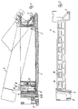
- 1 denotes a device frame which receives a knife contact strip, not shown.
- a knife contact 2 is shown from the knife contact strip.
- the device frame 1 carries eyelets 3, in which a housing 4 can be pivoted by means of pivot pin 5.
- the housing 4 serves to accommodate socket contacts and can be fixed at the end facing away from the pivot pin by a hook 6 on the device frame 1.
- the hook 6 engages behind a lug 7 which is fixed to the frame of the device.
- the hook 6 carries a fixed eyelet 8 which, by pressing on, enables the hook 6 to be pivoted counterclockwise in order to pivot it free.
- the housing 4 has a frame 9.
- a number of predetermined modules 10 (FIGS. 5-8) with socket contacts 11 arranged in the core openings 10' can be inserted in accordance with a block system (FIG. 9).
- the modules 10 can be inserted into the interior 9 ′ from above until the module-fixed support strips 12 come into contact and are fixed by means of a support body 13 when they reach their working position.
- the support bodies 13 are arranged on cut-off strip parts 14 of the longitudinal frame parts 9 ′′ and overlap contact surfaces 15 provided on the modules 10 in the region of recesses 26.
- the modules 10 are held firmly in the frame 9 by means of the support strips 12 and the support bodies 13.
- the longitudinal frame parts 9 ′′ have coding strips 16 which can be brought into effect with recesses 17 in the housings of the modules 10. Corresponding to the design of the coding strips 16 and recesses 17, incorrect insertion of the modules 10 is excluded.
- the socket contacts 11 lie in the core openings 10 ′ on support surfaces 23 and are fixed in the modules 10 by wall parts 25 pivoted down by means of a slide 24. The slider 24 can be locked in recesses 25 of the module housing.
- any desired number of modules 10 or also empty modules can be inserted into the frame, which in connection with one another result in the socket contact strip.
- the longitudinal frame parts 9 ′′ are firmly connected to one another by a transverse web 18, which prevents undesired twisting of the longitudinal frame parts 9 ′′ or bending thereof, which give rise to unsafe or inaccurate mounting of the modules 10.
- the web 18 has at least one groove 19 on one side and a tongue 20 on the opposite side, which can be brought into effect on the modules 10 with corresponding grooves 21 and tongues 22.
- the springs 22 and grooves 21 of the modules 10 enable their axial alignment with one another and with respect to the frame parts 9 ′′.
Landscapes
- Connector Housings Or Holding Contact Members (AREA)
- Details Of Connecting Devices For Male And Female Coupling (AREA)
- Mechanical Operated Clutches (AREA)
- Connection Of Motors, Electrical Generators, Mechanical Devices, And The Like (AREA)
Description
- Die Erfindung betrifft eine elektrische Kupplungsvorrichtung mit einer an einem Geräterahmen fest angeordneten Messerkontaktleiste und einer in einem Gehäuse untergebrachten Buchsenkontaktleiste, bei der das Gehäuse mit einem stirnseitigen Ende durch Gelenkzapfen am Geräterahmen anhängbar ist und mit dem anderen stirnseitigen Ende durch einen am Gehäuse angeordneten Haken und einer mit einer Rastöffnung versehenen geräterahmenfesten Rastfeder aneinander festlegbar sind, wobei das Gehäuse einen Rahmen aufweist und im Innenraum des Rahmens Buchsenkontakte angeordnet sind, die mit einem zugehörigen Arretiermittel im Gehäuse gesichert sind.
- Bei einer vielpoligen Steckvorrichtung (DE-U-7339199) mit an einer Steckdose schwenkbar angeordnetem Steckergehäuse finden in einem Kontaktträger des Steckergehäuses verrastete Einzelkontaktelemente Verwendung, die durch einen Arretierkamm gesichert sind. Ein Entnehmen oder Einsetzen von Einzelkontaktelementen hat jeweils die Entfernung des Arretierkamms zur Voraussetzung, was ein Herausfallen der übrigen Einzelkontaktelemente ermöglicht. Eine weitere Steckverbindung (DE-A-2806437) weist einen Stecker mit einem in einem Gehäuse angeordneten Kontaktträger auf. Der Kontaktträger ist durch mehrere aneinander gereihte Kontaktsegmente gebildet, die durch Vorsprünge und Aussparungen in der Art einer Nut-Federverbindung im Gehäuse bzw. an benachbarten Kontaktsegmenten befestigt sind. Abgesehen davon, daß diese Steckverbindung große Verschiebekräfte erforderlich macht, benötigt sie auch umständliche Montagearbeiten zum Befestigen der Kontaktsegmente. Bei einer weiteren Steckverbindung (FR-A-2098545) finden in einem Steckerrahmen Kontakte aufweisende Elemente Anwendung, die durch Aufschieben auf Leisten des Steckerrahmens in Verbindung mit elastischen Klemmgliedern im Steckerrahmen festlegbar sind. Diese Steckverbindung benötigt zu Kontaktierungen bzw. Trennungen wiederum große Verschiebekräfte und erfordert verlorene Freiabschnitte im Stekkerrahmen.
- Es ist Aufgabe der Erfindung einfache Maßnahmen zur sicheren veränderbaren Bestückung von Buchsenleistenkörpern mit Buchsenkontakten zu schaffen.
- Erfindungsgemäß ist hierzu vorgesehen, daß im Innenraum des Rahmens Buchsenkontakte aufnehmende Module angeordnet sind und daß die Module an den den Messerkontakten abgewandten Enden auf die Längsteile des Rahmens aufstützbare Stützleisten und im Abstand der Stützleisten Ausnehmungen mit Anlageflächen für an den Längsteilen angeordnete Stützkörper aufweisen. Auf diese Weise ist es möglich, durch Einsetzen von mit einer beliebigen Anzahl Buchsenkörpern bestückten Modulen in der Art eines Blocksystems vorbestimmt ausgebildete Buchsenkontaktleisten aufzurichten und in das Gehäuse anzuordnen. Hierbei kann der beibehaltene Rahmen Module verschiedener Bestückung und Länge aufnehmen und dadurch Buchsenkontaktleisten mit einer den jeweiligen Anforderungen entsprechenden Anzahl Buchsenkontakte bilden. So ist auch möglich zwischen oder zu Modulen mit darin angeordneten Buchsenkontakten Leermodule in Anwendung zu bringen. Außderdem bedarf das Einbringen der Module nur einfacher Steckvorgänge, wobei nach Erreichen der Arbeitsstellung der Module in dem Rahmen eine selbsttätige Fixierung der Module erreichbar ist. Bevorzugt sind die Stützkörper durch an den Rahmenlängsteilen angeschnittene Streifenteile, innen angeordnete Vorsprünge oder Anformungen gebildet. Die Streifenteile geben den Vorteil, daß bei Steckvorgängen der Module die Vorsprünge oder Anformungen durch die Modulgehäuse zunächst selbsttätig entgegen Werkstoffspannungen nach außen bewegt werden um bei Erreichen der Arbeitsstellung der Module selbsttätig über die Anlageflächen zurückzuschwenken. Zweckmäßig sind die Stützkörper mit vorbestimmten Abständen an den Rahmenlängsteilen ausgebildet, wobei der Abstand der Stützkörper voneinander nach einem insbesondere variablen Rastermaß erfolgen kann.
- In weiterer Ausgestaltung der Kupplungsvorrichtung ist vorgesehen, die Rahmenlängsteile innen mit Kodierkörpern zu versehen, die in Kodierausnehmungen der Module eingreifen. Die Kodiermittel verhindern ein Einsetzen falscher Module in den Rahmen. Die Kodierkörper können einfach durch in Einsteckrichtung der Module sich erstrekkende Leisten und die Ausnehmungen der Module durch in den Modulgehäusen ausgebildete korrespondierende Nuten gebildet sein.
- Schließlich ist noch vorgesehen, die Module in den Trennungsflächen zu benachbarten Modulen mit mindestens einer Nut-Federanordnung zu versehen. Die Nut-Federanordnung führt zu einer Ausrichtung der Module zueinander in Längsrichtung des Gehäuses. Außerdem verhindert die Nut-Federanordnung unerwünschte seitliche Bewegungen der Module zueinander und gegenüber den Rahmenteilen.
- Um bei Kupplungsvorrichtungen mit Gehäusen größerer Länge biegungssteife Rahmen zu erhalten, ist vorgesehen, daß die Rahmenlängsteile durch mindestens einen Quersteg miteinander fest verbunden sind. Die Querstege können dabei auf einer Seite mindestens eine mit den Nuten der Module querschnittsgleiche Feder und auf der anderen Seite mindestens eine mit den Federn der Module querschnittsgleiche Nut aufweisen. Es versteht sich, daß zu Buchsenkontaktgehäusen mit großer Breite zwei oder mehr Federn und Nuten an den Querstegen angeordnet sein können.
- Ferner ist noch vorgesehen, die Module mit einer Anzahl mit Buchsenkontakten bestückbare Kernöffnungen zu versehen, in die die Buchsenkontakte am Modulgehäuse abstützbar und durch Klemmglieder verrastbar sind. Als Klemmglieder können in die Kernöffnungen einbringbare Schieber dienen, die unmittelbar die Buchsenkontakte festlegen oder über einem modulgehäusefesten abbiegbaren Wandabschnitt die Fixierung der Buchsenkontakte in den Kernöffnungen ermöglichen.
- Die Erfindung ist anhand eines Ausführungsbeispiels in der Zeichnung verdeutlicht. Hierin bedeuten:
- Fig. 1
- eine Kupplungsvorrichtung im Schnitt,
- Fig. 2
- ein Buchsenkontaktgehäuse in Seitenansicht, teilweise im Schnitt,
- Fig. 3
- ein Buchsenkontaktgehäuse in Draufsicht,
- Fig. 4
- einen Schnitt nach der Linie IV - IV der Fig. 3,
- Fig. 5
- ein Modul für die Aufnahme von Buchsenkontakten in Vorderansicht, teilweise im Schnitt,
- Fig. 6
- ein Modul gemäß Fig. 5 in Seitenansicht,
- Fig. 7
- ein Modul gemäß Fig. 5 in Draufsicht,
- Fig. 8
- ein Modul anderer Ausführung in Draufsicht und
- Fig. 9
- ein Blocksystem mit Modulen für eine Buchsenkontaktleiste.
- In den Fig. ist mit 1 ein Geräterahmen bezeichnet, der eine nicht näher dargestellte Messerkontaktleiste aufnimmt. Von der Messerkontaktleiste ist ein Messerkontakt 2 dargestellt. Der Geräterahmen 1 trägt Ösen 3, in die ein Gehäuse 4 mittels Gelenkzapfen 5 schwenkbar einhängbar ist. Das Gehäuse 4 dient der Aufnahme von Buchsenkontakten und ist an dem dem Schwenkzapfen abgewandten Ende durch einen Haken 6 am Geräterahmen 1 festlegbar. Der Haken 6 hintergreift hierzu eine geräterahmenfeste Nase 7. Der Haken 6 trägt fest eine Öse 8, die durch Aufdrücken Abschwenkungen des Hakens 6 entgegen der Uhrzeigerdrehrichtung zum Freischwenken desselben ermöglicht. Es besteht die Möglichkeit abweichend den Haken 6 am Geräterahmen 1 und die Nase 7 am Gehäuse 4 anzuordnen.
- Das Gehäuse 4 weist, wie dies insbesondere die Fig. 3 erkennen läßt, einen Rahmen 9 auf. In dem Innenraum 9' des Rahmens 9 sind eine Anzahl vorbestimmte Module 10 (Fig. 5 - 8) mit in Kernöffnungen 10' angeordneten Buchsenkontakten 11 entsprechend einem Blocksystem (Fig. 9) einsteckbar. Die Module 10 sind von oben her bis zur Anlage von modulfesten Stützleisten 12 in den Innenraum 9' einbringbar und werden bei Erreichen ihrer Arbeitsstellung mittels Stützkörper 13 fixiert. Die Stützkörper 13 sind an angeschnittenen Streifenteilen 14 der Rahmenlängsteile 9'' angeordnet und übergreifen im Bereich von Ausnehmungen 26 vorgesehene Anlageflächen 15 an den Modulen 10. Mittels der Stützleisten 12 und der Stützkörper 13 sind die Module 10 fest im Rahmen 9 gehalten. Die Rahmenlängsteile 9'' weisen Kodierleisten 16 auf, die mit Ausnehmungen 17 in den Gehäusen der Module 10 zur Wirkung bringbar sind. Entsprechend der Ausbildung der Kodierleisten 16 und Ausnehmungen 17 sind Fehlsteckungen der Module 10 ausgeschlossen. Die Buchsenkontakte 11 liegen in den Kernöffnungen 10' an Stützflächen 23 an und sind durch mittels Schieber 24 abgeschwenkte Wandungsteile 25 in den Modulen 10 fixiert. Die Schieber 24 sind in Ausnehmungen 25 des Modulgehäuses verrastbar.
- Es versteht sich, daß in dem Rahmen beliebig ausgebildete und eine beliebige Anzahl Module 10, bzw. auch Leermodule einbringbar sind, die in Verbindung miteinander die Buchsenkontaktleiste ergeben. Die Rahmenlängsteile 9'' sind durch einen Quersteg 18 miteinander fest verbunden, wodurch unerwünschte Verwindungen der Rahmenlängsteile 9'' oder Verbiegungen derselben, die zu einer unsicheren bzw. ungenauen Halterung der Module 10 Anlaß geben,verhindert sind. Der Steg 18 weist auf einer Seite mindestens eine Nut 19 und an der gegenüberliegenden Seite eine Feder 20 auf, die mit korrespondierenden Nuten 21 und Federn 22 an den Modulen 10 zur Wirkung bringbar sind. Die Federn 22 und Nuten 21 der Module 10 ermöglichen deren axiale Ausrichtung zueinander und gegenüber den Rahmenteilen 9''.
Claims (8)
- Elektrische Kupplungsvorrichtung mit einer an einem Geräterahmen (1) fest angeordneten Messerkontaktleiste und einer in einem Gehäuse (4) untergebrachten Buchsenkontaktleiste, bei der das Gehäuse (4) mit einem stirnseitigen Ende durch Gelenkzapfen (5) am Geräterahmen (1) anhängbar ist und mit dem anderen stirnseitigen Ende durch einen am Gehäuse (4) angeordneten Haken (6) und einer mit einer Rastöffnung versehenen geräterahmenfesten Rastfeder aneinander festlegbar sind, wobei das Gehäuse (4) einen Rahmen (9) aufweist und im Innenraum (9') des Rahmens (9) Buchsenkontakte angeordnet sind, die mit einem zugehörigen Arretiermittel (13) im Gehäuse (4) gesichert sind, dadurch gekennzeichnet, daß im Innenraum (9') des Rahmens (9) Buchsenkontakte aufnehmende Module (10) angeordnet sind und daß die Module (10) an den den Messerkontakten (2) abgewandten Enden auf die Längsteile (9") des Rahmens (9) aufstützbare Stützleisten (12) und im Abstand der Stützleisten (12) Ausnehmungen (26) mit Anlageflächen (15) für an den Längsteilen (9") angeordnete Stützkörper (13) aufweisen.
- Kupplungsvorrichtung nach Anspruch 1, dadurch gekennzeichnet, daß die Stützkörper (13) als durch an den Längsteilen (9") des Rahmens (9) angeschnittene Streifenteile (14), innen angeordnete Vorsprünge oder Anformungen ausgebildet sind.
- Kupplungsvorrichtung nach Anspruch 1 und 2, dadurch gekennzeichnet, daß die Stützkörper (13) nach einem Rastermaß an den Längsteilen (9") des Rahmens (9) ausgebildet sind.
- Kupplungsvorrichtung nach Anspruch 3, dadurch gekennzeichnet, daß die Längsteile (9") des Rahmens in den Innenraum (9') einragende Kodierkörper (16) aufweisen, die in Kodierausnehmungen (17) der Module (10) eingreifen.
- Kupplungsvorrichtung nach Anspruch 4, dadurch gekennzeichnet, daß die Kodierkörper (16) durch in Steckrichtung der Module (10) sich erstreckende Leisten und die Kodierausnehmungen (17) durch in den Gehäusen der Module (10) ausgebildete korrespondierende Nuten gebildet sind.
- Kupplungsvorrichtung nach Anspruch 1, dadurch gekennzeichnet, daß die Module (10) in den Trennungsflächen zu benachbarten Modulen mindestens eine Nut- bzw. Federanordnung (21,22) aufweisen.
- Kupplungsvorrichtung nach Anspruch 6, dadurch gekennzeichnet, daß die Längsteile (9") des Rahmens durch mindestens einen Quersteg (18) miteinander fest verbunden sind, der auf einer Seite mindestens eine mit den Nuten (21) der Module querschnittsgleiche Feder (20) und auf der anderen Seite mindestens eine mit den Federn (22) der Module (10) querschnittsgleiche Nut (19) aufweist.
- Kupplungsvorrichtung nach Anspruch 1, dadurch gekennzeichnet, daß die Module (10) eine Anzahl vorbereitete, mit Buchsenkontakten (11) bestückbare Kernöffnungen (10') aufweisen und daß die Buchsenkontakte (11) in den Kernöffnungen (10') am Gehäuse des Moduls abstützbar und durch Klemmglieder (24,25) verrastbar sind.
Applications Claiming Priority (3)
| Application Number | Priority Date | Filing Date | Title |
|---|---|---|---|
| DE3834651 | 1988-10-12 | ||
| DE3834651A DE3834651A1 (de) | 1988-10-12 | 1988-10-12 | Elektrische kupplungsvorrichtung |
| PCT/EP1989/001196 WO1990004271A1 (de) | 1988-10-12 | 1989-10-10 | Electrische kupplungsvorrichtung |
Publications (2)
| Publication Number | Publication Date |
|---|---|
| EP0413774A1 EP0413774A1 (de) | 1991-02-27 |
| EP0413774B1 true EP0413774B1 (de) | 1996-01-03 |
Family
ID=6364902
Family Applications (1)
| Application Number | Title | Priority Date | Filing Date |
|---|---|---|---|
| EP89911372A Expired - Lifetime EP0413774B1 (de) | 1988-10-12 | 1989-10-10 | Elektrische kupplungsvorrichtung |
Country Status (7)
| Country | Link |
|---|---|
| US (1) | US5114360A (de) |
| EP (1) | EP0413774B1 (de) |
| JP (1) | JPH03502984A (de) |
| KR (1) | KR900702600A (de) |
| AT (1) | ATE132660T1 (de) |
| DE (2) | DE3834651A1 (de) |
| WO (1) | WO1990004271A1 (de) |
Families Citing this family (10)
| Publication number | Priority date | Publication date | Assignee | Title |
|---|---|---|---|---|
| JP2682301B2 (ja) * | 1991-09-10 | 1997-11-26 | 住友電装株式会社 | 集合コネクタ |
| JP2698841B2 (ja) * | 1992-10-28 | 1998-01-19 | 矢崎総業株式会社 | 低挿入力コネクタ |
| DE4311781C1 (de) * | 1993-04-09 | 1994-06-23 | Amphenol Tuchel Elect | Stecker oder Buchse für einen Steckverbinder |
| DE19545273C2 (de) * | 1995-12-05 | 1997-10-16 | Kostal Leopold Gmbh & Co Kg | Elektrische Kupplungsvorrichtung |
| DE202012010735U1 (de) | 2012-11-12 | 2012-12-03 | Amphenol-Tuchel Electronics Gmbh | Modularer Steckverbinder |
| JP6244832B2 (ja) * | 2013-11-08 | 2017-12-13 | 第一精工株式会社 | 電気コネクタ |
| DE102015104562B4 (de) | 2015-03-26 | 2018-12-06 | Amphenol-Tuchel Electronics Gmbh | Halterahmen und Steckverbinder mit Halterahmen für ein modulares Steckverbindersystem |
| DE202015009386U1 (de) | 2015-09-04 | 2017-05-24 | Amphenol-Tuchel Electronics Gmbh | System aus Steckverbinder-Modulrahmen und Adapterelementen sowie modularen Steckverbinder mit einem solchen System |
| US20170111451A1 (en) * | 2015-10-15 | 2017-04-20 | LiThul LLC | Methods and Apparatus For Remotely Monitoring Access To Rack Mounted Server Cabinets |
| US9772663B2 (en) | 2015-10-15 | 2017-09-26 | LiThul LLC | System and method for distributing power to rack mounted servers |
Family Cites Families (15)
| Publication number | Priority date | Publication date | Assignee | Title |
|---|---|---|---|---|
| US3042894A (en) * | 1958-07-17 | 1962-07-03 | Fox Benjamin | Electrical coupling device for miniature terminals |
| US3072340A (en) * | 1960-09-16 | 1963-01-08 | Cannon Electric Co | Electrical connector insulator block construction |
| NL135885C (de) * | 1962-06-18 | 1900-01-01 | ||
| GB1014915A (en) * | 1963-07-09 | 1965-12-31 | Amp Inc | Improvements in and relating to bipartite housings for electrical connectors |
| FR1531416A (fr) * | 1967-02-28 | 1968-07-05 | Fr Metallo Soc | Connecteur pour circuits imprimés |
| FR2098545A5 (de) * | 1970-07-20 | 1972-03-10 | Socapex | |
| US3668605A (en) * | 1970-08-10 | 1972-06-06 | North Electric Co | Multi-point program plug and receptacle connector arrangement having positive alignment prior to positive mating |
| DE7339199U (de) * | 1973-11-02 | 1978-11-02 | Robert Bosch Gmbh, 7000 Stuttgart | Vielpolige Steckvorrichtung |
| DE2806437A1 (de) * | 1978-02-15 | 1979-08-16 | Hans Eder | Elektrische steckerverbindung |
| DE3310194A1 (de) * | 1983-03-21 | 1984-09-27 | Siemens AG, 1000 Berlin und 8000 München | Verriegelungsvorrichtung fuer einen steckverbinder |
| FR2544558B1 (fr) * | 1983-04-15 | 1986-06-27 | Deutsch Co | Connecteur perfectionne |
| US4596436A (en) * | 1985-03-25 | 1986-06-24 | Amp Incorporated | Electrical connector housing assembly comprising housing frame containing housing modules |
| GB8615183D0 (en) * | 1986-06-21 | 1986-07-23 | Lucas Ind Plc | Electrical connectors |
| DE3634695A1 (de) * | 1986-10-11 | 1988-04-21 | Reinshagen Kabelwerk Gmbh | Vielpolige verriegelbare elektrische steckverbindung |
| GB8810591D0 (en) * | 1988-05-05 | 1988-06-08 | Amp Gmbh | Electrical connector housing |
-
1988
- 1988-10-12 DE DE3834651A patent/DE3834651A1/de not_active Withdrawn
-
1989
- 1989-10-10 EP EP89911372A patent/EP0413774B1/de not_active Expired - Lifetime
- 1989-10-10 JP JP1510604A patent/JPH03502984A/ja active Pending
- 1989-10-10 US US07/499,410 patent/US5114360A/en not_active Expired - Fee Related
- 1989-10-10 WO PCT/EP1989/001196 patent/WO1990004271A1/de not_active Ceased
- 1989-10-10 AT AT89911372T patent/ATE132660T1/de not_active IP Right Cessation
- 1989-10-10 DE DE58909560T patent/DE58909560D1/de not_active Expired - Fee Related
- 1989-10-10 KR KR1019900701246A patent/KR900702600A/ko not_active Ceased
Also Published As
| Publication number | Publication date |
|---|---|
| WO1990004271A1 (de) | 1990-04-19 |
| EP0413774A1 (de) | 1991-02-27 |
| KR900702600A (ko) | 1990-12-07 |
| ATE132660T1 (de) | 1996-01-15 |
| DE58909560D1 (de) | 1996-02-22 |
| JPH03502984A (ja) | 1991-07-04 |
| US5114360A (en) | 1992-05-19 |
| DE3834651A1 (de) | 1990-04-19 |
Similar Documents
| Publication | Publication Date | Title |
|---|---|---|
| DE102015103563B4 (de) | Halterahmen zum Aufnehmen von modularen Kontakteinsätzen | |
| DE2850093C2 (de) | Halterungsanordnung für Schaltungsplatten | |
| EP3345255B1 (de) | System bestehend aus einem steckverbinder-modulrahmen und adapterelementen | |
| EP3905451A1 (de) | Steckverbindermodul mit modulelement | |
| DE2508075C2 (de) | Elektrischer Verbinderkontakt | |
| DE102018117723B4 (de) | Aufnahmeeinheit für kontaktstift in einem zähleranschlussblock sowie zähleranschlussblock und ein stromzähler | |
| DE60001549T2 (de) | Elektrischer verbinder für ein ein/ausgabemodul | |
| DE4102784C2 (de) | Anschlußklemme | |
| DE60131714T2 (de) | Stecker oder Adapter für optisches Kabel | |
| DE69111350T2 (de) | Verriegelungsmechanismus für Datenverbinder. | |
| DE69711369T2 (de) | Modularer Kammverbinder für Schnittstellenrelais | |
| DE102010010259A1 (de) | Steckverbinder und Gegensteckverbinder | |
| EP0413774A1 (de) | Electrische kupplungsvorrichtung. | |
| DE4311781C1 (de) | Stecker oder Buchse für einen Steckverbinder | |
| DE3126306C2 (de) | Stecksockel für mehrpolige Niederspannungs-Schutzschalter | |
| EP2264470B1 (de) | Anschlusssystem für Stromzähler | |
| DE3236608C2 (de) | Kodiereinrichtung zum Kodieren des Einschubplatzes von elektronischen Baugruppen in einem Gehäuse | |
| DE2315062A1 (de) | Vielfachsteckanschlusstueck | |
| DE2448349C2 (de) | Verbinderanordnung mit einem mit einer gedruckten Schaltungsplatte verbundenen Verbinder | |
| EP0749180B1 (de) | Steckverbindergehäuse | |
| DE3623993A1 (de) | Elektrische kontaktsteckverbindung | |
| DE69303875T2 (de) | Adapter mit einer Sicherungsgreifvorrichtung zum Verbinden eines elektrischen Geräts auf eine Energieversorgungssammelschiene | |
| DE2534292C2 (de) | ||
| DE102020104099B4 (de) | Aufnahmeeinheit für Kontaktstift in einem Zähleranschlussblock und System mit einem Zähleranschlussblock und einer Überbrückungsvorrichtung | |
| DE2935370C2 (de) | Gehäuse für eine elektrische Steckverbindung |
Legal Events
| Date | Code | Title | Description |
|---|---|---|---|
| PUAI | Public reference made under article 153(3) epc to a published international application that has entered the european phase |
Free format text: ORIGINAL CODE: 0009012 |
|
| 17P | Request for examination filed |
Effective date: 19900709 |
|
| AK | Designated contracting states |
Kind code of ref document: A1 Designated state(s): AT BE CH DE FR GB IT LI LU NL SE |
|
| 17Q | First examination report despatched |
Effective date: 19930804 |
|
| RAP1 | Party data changed (applicant data changed or rights of an application transferred) |
Owner name: FRAMATOME CONNECTORS DAUT + RIETZ GMBH & CO. KG |
|
| RAP1 | Party data changed (applicant data changed or rights of an application transferred) |
Owner name: FRAMATOME CONNECTORS DAUT + RIETZ GMBH |
|
| GRAA | (expected) grant |
Free format text: ORIGINAL CODE: 0009210 |
|
| AK | Designated contracting states |
Kind code of ref document: B1 Designated state(s): AT BE DE FR GB IT NL SE |
|
| PG25 | Lapsed in a contracting state [announced via postgrant information from national office to epo] |
Ref country code: GB Effective date: 19960103 Ref country code: BE Effective date: 19960103 |
|
| REF | Corresponds to: |
Ref document number: 132660 Country of ref document: AT Date of ref document: 19960115 Kind code of ref document: T |
|
| ET | Fr: translation filed | ||
| REF | Corresponds to: |
Ref document number: 58909560 Country of ref document: DE Date of ref document: 19960222 |
|
| ITF | It: translation for a ep patent filed | ||
| PG25 | Lapsed in a contracting state [announced via postgrant information from national office to epo] |
Ref country code: SE Effective date: 19960403 |
|
| GBV | Gb: ep patent (uk) treated as always having been void in accordance with gb section 77(7)/1977 [no translation filed] |
Effective date: 19960103 |
|
| PLBE | No opposition filed within time limit |
Free format text: ORIGINAL CODE: 0009261 |
|
| STAA | Information on the status of an ep patent application or granted ep patent |
Free format text: STATUS: NO OPPOSITION FILED WITHIN TIME LIMIT |
|
| 26N | No opposition filed | ||
| PG25 | Lapsed in a contracting state [announced via postgrant information from national office to epo] |
Ref country code: NL Effective date: 19970501 |
|
| NLV4 | Nl: lapsed or anulled due to non-payment of the annual fee |
Effective date: 19970501 |
|
| PGFP | Annual fee paid to national office [announced via postgrant information from national office to epo] |
Ref country code: AT Payment date: 19980929 Year of fee payment: 10 |
|
| PGFP | Annual fee paid to national office [announced via postgrant information from national office to epo] |
Ref country code: FR Payment date: 19981030 Year of fee payment: 10 |
|
| PGFP | Annual fee paid to national office [announced via postgrant information from national office to epo] |
Ref country code: DE Payment date: 19981230 Year of fee payment: 10 |
|
| PG25 | Lapsed in a contracting state [announced via postgrant information from national office to epo] |
Ref country code: AT Free format text: LAPSE BECAUSE OF NON-PAYMENT OF DUE FEES Effective date: 19991010 |
|
| PG25 | Lapsed in a contracting state [announced via postgrant information from national office to epo] |
Ref country code: FR Free format text: LAPSE BECAUSE OF NON-PAYMENT OF DUE FEES Effective date: 20000630 |
|
| PG25 | Lapsed in a contracting state [announced via postgrant information from national office to epo] |
Ref country code: DE Free format text: LAPSE BECAUSE OF NON-PAYMENT OF DUE FEES Effective date: 20000801 |
|
| REG | Reference to a national code |
Ref country code: FR Ref legal event code: ST |
|
| PG25 | Lapsed in a contracting state [announced via postgrant information from national office to epo] |
Ref country code: IT Free format text: LAPSE BECAUSE OF NON-PAYMENT OF DUE FEES;WARNING: LAPSES OF ITALIAN PATENTS WITH EFFECTIVE DATE BEFORE 2007 MAY HAVE OCCURRED AT ANY TIME BEFORE 2007. THE CORRECT EFFECTIVE DATE MAY BE DIFFERENT FROM THE ONE RECORDED. Effective date: 20051010 |