EP0413012B1 - Dispositif de liaison liberable pour elements de jeux de construction - Google Patents
Dispositif de liaison liberable pour elements de jeux de construction Download PDFInfo
- Publication number
- EP0413012B1 EP0413012B1 EP90902996A EP90902996A EP0413012B1 EP 0413012 B1 EP0413012 B1 EP 0413012B1 EP 90902996 A EP90902996 A EP 90902996A EP 90902996 A EP90902996 A EP 90902996A EP 0413012 B1 EP0413012 B1 EP 0413012B1
- Authority
- EP
- European Patent Office
- Prior art keywords
- socket
- sleeve
- locking element
- connection device
- accordance
- Prior art date
- Legal status (The legal status is an assumption and is not a legal conclusion. Google has not performed a legal analysis and makes no representation as to the accuracy of the status listed.)
- Expired - Lifetime
Links
- 238000010276 construction Methods 0.000 claims description 11
- 230000004323 axial length Effects 0.000 claims description 6
- 238000003780 insertion Methods 0.000 claims description 4
- 230000037431 insertion Effects 0.000 claims description 4
- 238000006073 displacement reaction Methods 0.000 claims 1
- 239000013013 elastic material Substances 0.000 claims 1
- 238000009877 rendering Methods 0.000 claims 1
- 239000011324 bead Substances 0.000 description 56
- 241000209035 Ilex Species 0.000 description 19
- 238000010168 coupling process Methods 0.000 description 10
- 238000005859 coupling reaction Methods 0.000 description 10
- 230000008878 coupling Effects 0.000 description 9
- 239000000463 material Substances 0.000 description 6
- 238000005192 partition Methods 0.000 description 4
- 230000002829 reductive effect Effects 0.000 description 4
- 238000004519 manufacturing process Methods 0.000 description 3
- 238000000034 method Methods 0.000 description 3
- 230000008569 process Effects 0.000 description 3
- 241001136792 Alle Species 0.000 description 2
- 230000000903 blocking effect Effects 0.000 description 2
- 230000006835 compression Effects 0.000 description 2
- 238000007906 compression Methods 0.000 description 2
- 230000002787 reinforcement Effects 0.000 description 2
- 230000003014 reinforcing effect Effects 0.000 description 2
- 230000000284 resting effect Effects 0.000 description 2
- 238000000926 separation method Methods 0.000 description 2
- 206010041953 Staring Diseases 0.000 description 1
- 230000009471 action Effects 0.000 description 1
- 230000002411 adverse Effects 0.000 description 1
- 238000013459 approach Methods 0.000 description 1
- 230000009193 crawling Effects 0.000 description 1
- 230000006378 damage Effects 0.000 description 1
- -1 dirt Substances 0.000 description 1
- 230000000694 effects Effects 0.000 description 1
- 230000008030 elimination Effects 0.000 description 1
- 238000003379 elimination reaction Methods 0.000 description 1
- 230000001771 impaired effect Effects 0.000 description 1
- 238000009434 installation Methods 0.000 description 1
- 230000002452 interceptive effect Effects 0.000 description 1
- 239000002184 metal Substances 0.000 description 1
- 230000000717 retained effect Effects 0.000 description 1
- 239000004576 sand Substances 0.000 description 1
- 238000007789 sealing Methods 0.000 description 1
- 210000002023 somite Anatomy 0.000 description 1
- 230000007480 spreading Effects 0.000 description 1
- XLYOFNOQVPJJNP-UHFFFAOYSA-N water Substances O XLYOFNOQVPJJNP-UHFFFAOYSA-N 0.000 description 1
Images


Classifications
-
- F—MECHANICAL ENGINEERING; LIGHTING; HEATING; WEAPONS; BLASTING
- F16—ENGINEERING ELEMENTS AND UNITS; GENERAL MEASURES FOR PRODUCING AND MAINTAINING EFFECTIVE FUNCTIONING OF MACHINES OR INSTALLATIONS; THERMAL INSULATION IN GENERAL
- F16B—DEVICES FOR FASTENING OR SECURING CONSTRUCTIONAL ELEMENTS OR MACHINE PARTS TOGETHER, e.g. NAILS, BOLTS, CIRCLIPS, CLAMPS, CLIPS OR WEDGES; JOINTS OR JOINTING
- F16B7/00—Connections of rods or tubes, e.g. of non-circular section, mutually, including resilient connections
- F16B7/04—Clamping or clipping connections
-
- A—HUMAN NECESSITIES
- A63—SPORTS; GAMES; AMUSEMENTS
- A63H—TOYS, e.g. TOPS, DOLLS, HOOPS OR BUILDING BLOCKS
- A63H33/00—Other toys
- A63H33/04—Building blocks, strips, or similar building parts
- A63H33/042—Mechanical, electrical, optical, pneumatic or hydraulic arrangements; Motors
-
- A—HUMAN NECESSITIES
- A63—SPORTS; GAMES; AMUSEMENTS
- A63H—TOYS, e.g. TOPS, DOLLS, HOOPS OR BUILDING BLOCKS
- A63H33/00—Other toys
- A63H33/04—Building blocks, strips, or similar building parts
- A63H33/10—Building blocks, strips, or similar building parts to be assembled by means of additional non-adhesive elements
- A63H33/108—Building blocks, strips, or similar building parts to be assembled by means of additional non-adhesive elements with holes
-
- A—HUMAN NECESSITIES
- A63—SPORTS; GAMES; AMUSEMENTS
- A63H—TOYS, e.g. TOPS, DOLLS, HOOPS OR BUILDING BLOCKS
- A63H33/00—Other toys
- A63H33/04—Building blocks, strips, or similar building parts
- A63H33/10—Building blocks, strips, or similar building parts to be assembled by means of additional non-adhesive elements
- A63H33/12—Perforated strips or the like assembled by rods, bolts, or the like
Definitions
- the invention relates to a releasable connecting device for connecting at least two toy components, each having a bore, with a sleeve intended for insertion into the bore of the components, which has a cylindrical shaft section and in one end part of the longitudinal slots to achieve a radial elasticity and which has a radially protruding, narrow, outer edge bead at the free end of this end part, which is intended to positively engage behind one component after inserting the sleeve into the bore of the components, and with a contact flange at the end of the edge facing away from the edge bead cylindrical shaft sections.
- a releasable connecting device of the type mentioned is known from Swiss Patent No. 655 247.
- two toy components to be connected to one another are connected by means of an essentially cylindrical sleeve that passes through both bores.
- the sleeve has two longitudinal slots in one of its end regions, which bring about radial elasticity of this end region.
- the sleeve is at the slotted end with a radially outer Edge bead provided.
- the sleeve has an outer, annular flange.
- the two components to be connected to one another are each provided with an annular recess on the outside of their bores.
- the sleeve with the edge bead end is pushed through the bore of the two components, which is easily possible because of the radial elasticity of the slotted end region of the sleeve.
- the edge bead of the sleeve engages in the annular recess of one component, while the annular flange of the sleeve comes to rest in the annular recess of the other component, so that the two components are held together by the sleeve.
- a detachable connecting device of the type mentioned is also known from Swiss Patent No. 658 887.
- a sleeve of the type described above is designed as a double sleeve in that the sleeve is slotted at both ends and has an outer edge bead, the aforementioned annular flange being attached in the longitudinal center of the sleeve.
- Such a sleeve serves to releasably connect two components, the bore ends of which are provided on both wall sides of each component with annular recesses.
- a bolt-shaped locking element is captively inserted into the sleeve and can be moved in two positions relative to the sleeve, in the first position an end section at the free end of the locking element, the inner surface of the sleeve in the region of the radial plane of the edge bead of touched inside and in the second position from the inner surface of the sleeve in the region of the radial plane of the bead.
- a fastener for releasably connecting two metal sheets is known per se from Swiss patent specification No. 609 752.
- the fastener consists of a grommet and a pin part that is injection-molded with the eyelet via predetermined breaking points.
- the pin part In the initial state, the pin part is axially extended from a central hole in the eyelet.
- the eyelet has a contact flange at one end. Following the flange, it has a circumferential groove which is rectangular in cross section and in axial section. At the circumferential groove adjoin two expanding jaws with a rectangular cross section, which are tapered at their free ends. The cross section of the expanding jaws projects beyond the cross section of the circumferential groove on all sides.
- the fastener is first inserted through a rectangular opening in the first sheet, the cross-sectional dimensions of which are larger than the cross-section of the groove but smaller than the cross-section of the expanding jaws. Because the pin part is still removed from the central hole in the eyelet, the expansion jaws can deflect so that the first plate snaps into the groove. Subsequently, after the predetermined breaking points have been severed, the pin part is pushed axially into the central bore, where it is held axially immovably by a snap element and thus permanently secures the eyelet on the first sheet.
- the expanding jaws can now be inserted through a larger, also rectangular opening in the second sheet. A rectangular end section of the pin part engages between the two expanding jaws. By turning the pin part, the two expanding jaws can be released from their untensioned Position are spread apart so that their side walls are clamped non-positively in the opening of the second sheet.
- This known fastener is not suitable for toy components because it is permanently snapped onto the first sheet and because it requires two different hole sizes for the two sheets.
- the fastener is not suitable for centering the two sheets to each other because the first sheet has play in the groove. The two sheets must therefore be centered against each other by additional parts. Because the spreading jaws only grip the opening of the second plate, a precise contact between the two plates is not guaranteed. If the fastener remains in the spread position of the expansion jaws for a longer period of time, the crawling of the plastic material loses their property of springing back into the starting position.
- the device according to the invention can be easily removed from both components.
- the two components are positioned exactly radially and axially to one another, because the cylindrical shaft section centers the two components relative to one another and the narrow edge bead engages behind the second component in a form-fitting manner.
- the narrow edge bead does not protrude, so that it does not hinder the arrangement of further components during construction. Because the radially elastic end part of the sleeve is secured in its unclamped position in the locked position of the locking element, a longer stay in this locked position does not lead to creeping of the material and the connecting device can therefore be used both in the unlocked and in the locked position stay fixed for a long time.
- the invention also relates to toy components for a releasable connecting device according to the invention, with at least one cylindrical bore for receiving the cylindrical sleeve of the connecting device.
- the component according to the invention has the features specified in claim 13.
- the sleeve 1 shown in FIGS. 1 and 2 of the connecting device according to the invention has a rigid, cylindrical part 2 and a part 4 provided with four longitudinal slots 3 and therefore radially elastic, the longitudinal slots 3 being at angular intervals of 90 °.
- the elastic part 4 is provided at its end with an outer, also slotted bead 5.
- the elastic part 4 has a circumferential groove 6 of reduced outer diameter, which ensures the radial elasticity of the sleeve end and allows the sleeve end to be sprung radially outwards.
- the axial length of the circumferential groove 6 is smaller than the length of the part 2.
- its cylindrical inner wall is provided with four rectangular projections 7.
- the inner wall has four rectangular recesses 8, which extend as far as the sleeve end provided with the edge bead 5, and are delimited on both sides in the circumferential direction by projections 8 ′ projecting radially inwards.
- a locking element 9 shown in FIGS. 3 and 4 has a plug part 10 and a handle 11 which is integrally formed with the plug part 10 via a plate-like flange 12.
- the plug part 10 has a first, essentially cylindrical section which is provided with an annular recess or groove 13 into which the rectangular projections 7 of the sleeve 1 of FIGS. 1 and 2 fit.
- a second section adjoins this cylindrical section as an end region, which is provided with four longitudinal ribs 14.
- the longitudinal ribs 14 have flat outer surfaces 15 which fit into the rectangular recesses 8 of the sleeve 1 of FIGS. 1 and 2 with respect to width, length and radial dimension.
- the handle 11 is sleeve-shaped and has an outer edge bead 16 for its axial actuation and two wings 17 for its rotary actuation.
- the cylindrical inner wall of the handle 11 is provided with four annular groove sections 18 which are each separated by shorter sections 19 of the cylindrical inner wall of the handle 11 in the circumferential direction.
- the width of this shorter section 19 is at most equal to the width of the longitudinal slots 3 of the sleeve 1 of FIGS. 1 and 2.
- the meaning of the sections 18 and 19 on the inner wall of the handle 11 will be explained later.
- the plate-like flange 12 has circular incisions 20 which only have an aesthetic function which facilitates handling.
- the plug part 10 of the locking element 9 (FIGS. 3, 4) is inserted into the sleeve 1 (FIGS. 1, 2).
- the radially inner projections 7 of the sleeve 1 snap into the annular recess 13 of the plug part 10 of the locking element 9 after overcoming a certain elastic resistance.
- the sleeve 1 and the locking element 9 can no longer be displaced relative to one another in the axial direction, but can be rotated relative to one another.
- the axial lengths of the sleeve 1 and the plug part 10 of the locking element 9 are also matched to one another such that in the mentioned state of the axial locking of the sleeve 1 with the locking element 9, on the one hand the edge of the sleeve 1 opposite the edge bead 5 rests on the plate-like flange 12 of the locking element 9, and on the other hand the end face of the plug part 10 of the locking element 9 is flush with the end face of the edge bead 5 of the sleeve 1.
- 5 and 6 are perspective views of the two sides of the connecting device after the described insertion of the locking element 9 into the sleeve 1. 5 that the longitudinal ribs 14 of the plug part 10 of the locking element 9 come to lie in the radial direction in the inner part of the longitudinal slots 3 of the sleeve 1. Since the radial dimension of the longitudinal ribs 14 is a small amount larger than the radius of the cylindrical, slotted and elastic part 4 of the sleeve 1, the rotational position of the locking element 9 shown in FIG. 5 results with respect to the sleeve 1 when the locking element 9 is inserted in the sleeve 1 without constraint, since here the slightest mechanical resistance has to be overcome.
- FIG. 7 and 8 show a first position of the connecting device consisting of the sleeve 1 and the locking element 9 when inserted into the bores of the two components 21 and 22 to be connected.
- the plug-shaped locking element 9 is already inserted into the sleeve 1, as previously explained, and in this position due to the projections 7 of the sleeve 1 and the recesses 13 of the plug part 10 of the locking element 9, but axially inseparable rotatably held.
- the locking element 9 is now rotated in its position according to FIGS. 9 and 10 clockwise or counterclockwise by actuating its handle 11.
- the sleeve 1 is held in the direction of rotation in the components 21, 22, since the cams 24 of the components 21 engage in the longitudinal slots 3 of the sleeve 1.
- the locking element 9 rotates with its plug part 10 lying in the sleeve 1.
- the longitudinal ribs 14 snap into the correspondingly shaped, rectangular recesses 8 of the inner wall of the sleeve 1, which is both felt and audible when the handle 11 is turned.
- the elastic part 4 of the sleeve 1 provided with the slits 3 snaps back into its cylindrical, untensioned position, as shown in FIGS. 11 and 12.
- the locking element is possible 9 by means of the handle 11 clockwise or counterclockwise by a further 45 °, so that the longitudinal ribs 14 of the locking element 9 again lie opposite the longitudinal slots 3 of the sleeve 1 and protrude into the latter, as is shown in FIGS. 9 and 10. Then the locking element 9 together with the sleeve 1 can be pulled out of the holes in the components 21, 22, as a result of which the components are separated from one another again.
- the cylindrical inner wall of the handle 11 which is open to the outside, is provided with four annular groove sections 18, which are separated from one another by shorter sections 19 of the cylindrical inner wall of the handle 11.
- the purpose of this configuration of the cylindrical cavity of the handle 11 is to be able to accommodate the edge bead 5 of the sleeve 1 of a further connecting device of the present type. If a connecting device, as shown for example in FIG. 5, is inserted into the cavity of the handle 11 according to FIGS. 3 and 6, the slotted edge bead 5 of the sleeve 1 of this second connecting device snaps into the groove sections 18 of the handle 11 of the first connecting device a.
- the shorter sections 19 of the cylindrical inner wall of the handles 11 of the first connecting device perform the same function as the cams 24 described above in the recess 23 of the components 21 (FIGS. 8, 10, 12), that is to say by engaging in the longitudinal slots 3 the sleeve 1 prevent rotation of the sleeve 1 when the locking element 9 rotates to lock the sleeve 1.
- the groove sections 18 and the separating sections 19 therefore allow a further connecting device of the same type for further components to be plugged onto a connecting device according to FIGS. 7, 9 and 11.
- the connecting device again consists of a sleeve 25 and a locking element 26 inserted into the sleeve 25, which is rotatable in the sleeve 25, but is fixedly mounted in the axial direction.
- Both the sleeve 25 and the locking element 26 are designed practically the same as the sleeve 1 and the locking element 9 of FIGS. 1 to 12.
- the only difference is that the outer end face 27 of the locking element 26 is set back inwards in relation to the outer end face 28 of the sleeve 25, whereas in the embodiment according to FIGS. 5, 7, 9 and 11 these end faces lie in the same plane. It is therefore unnecessary to explain the sleeve 25 and the locking element 26 of FIG. 13 again in detail.
- the one component 30 of the two components 29 and 30, which are connected to one another by the connecting device with the sleeve 25 and the locking element 26, is formed substantially differently from FIGS. 7 to 12.
- the component 29 corresponds to the component 22 of FIGS. 7, 9 and 11.
- the component 30 instead of the radial cams 24, the component 30 has a diametrically extending transverse web 31, the width of which is at most equal to the width and preferably somewhat smaller than the width of the longitudinal slots 32 the sleeve 25 is.
- the component 30 is again provided with an annular recess 33, into which the edge bead 34 of the sleeve 25 engages.
- the crosspiece 31 can optionally have a larger dimension in the axial direction and be designed as a transverse wall.
- the connecting device in turn comprises a sleeve 51 and a locking element 52 which is rotatably but axially fixed in the sleeve 51.
- the sleeve 51 differs from the sleeve 1 of FIGS. 1 and 2 only in that it is provided with a circular flange 53 at its non-slotted end.
- the locking element 52 mounted in the sleeve 51 corresponds to the locking element 9 of FIGS. 3 and 4.
- the sleeve 51 is also provided on the inner surface of the flange 53 with an annular groove 54, in which an elastic ring 55 with a high coefficient of friction is received, for example an O-ring.
- the connecting device consisting of the sleeve 51 and the locking element 52 connects two components 56 and 57, of which one component 56 is a rod with annular recesses 58 and the other component 57 is part of a cuboid component with an inner collar 59 is.
- the connecting device is completely inserted into the bores of the two components 56 and 57, so that the sleeve 51 engages at its one slotted end with the edge bead 60 over the end face of the collar 59 of the component 57.
- the flange 53 of the sleeve 51 presses the elastic ring 55 onto a surface of the annular recess 58 of the component 56.
- the ring 55 thus acts as a friction element and therefore prevents the sleeve 51 from rotating within the bore of the component 56. Therefore, the connecting device shown can be locked or unlocked by rotating the locking element 52 in the manner already explained, without the sleeve 51 also rotating.
- the component 57 designed as a component with an inner collar 59
- other components can of course also be connected to the connecting device according to FIG. 14.
- the component 57 can be the same rod as the component 56.
- the components can be used and combined practically as desired are, that is also suitable for pushing through shafts, since their bores do not have to have any protruding projections.
- the handling of the connecting device according to FIG. 14 is somewhat cumbersome. When inserting and locking, a relatively strong pressure must be exerted on the handle of the locking element 52 in order to release the elastic ring 55 of the sleeve 51 in the recess 58 Compress component 56. The handle of the locking element 52 must then be rotated in order to lock the sleeve 51 while maintaining the application of pressure.
- the axial length of the described sleeves 1, 25, 51 of FIGS. 11, 13 and 14 and the thickness of the components 21, 22; 29, 30 and 56, 57 are, of course, interrelated, since the components must lie between the slotted edge bead of the respective sleeve and the flange of the associated locking element.
- all components in a kit normally have dimensions that are derived from a fixed module of the kit by integer division or multiplication (e.g. 1/4, 1/2, 3/4, 1, 2 ... etc.), the number of required connecting devices of the present type with different lengths is severely limited.
- the length of the sleeve including the slotted bead should be a multiple of the smallest thickness of the components. If in a component of the kit the relevant thickness of the component deviates from the module-related standard for design reasons, as is the case, for example, with component 57 in FIG. 14, then this different, smaller thickness of the component together with the axial dimension of the collar should 59 again result in the minimum and standardized thickness mentioned.
- the sleeve 101 of the connecting device according to the invention shown in FIGS. 15 and 16 has a substantially cylindrical sleeve part 102 and a plate-like flange 103 formed thereon.
- the end part 104a of the sleeve 101 facing away from the flange 103 is provided with four longitudinal slots 104, which bring about a radial elasticity of this sleeve end.
- an outer edge bead 105 and, offset in the longitudinal direction, an inner annular projection 106 are also formed on the sleeve part 104a.
- the projection 106 projects radially inward from a cylindrical inner surface 106a at the free end of the end part 104a.
- the sleeve end has a circumferential groove 107, which ensures the radial elasticity of the sleeve end and allows the sleeve end to be sprung radially outwards.
- the cylindrical inner wall of the sleeve 101 is provided with an annular projection 108.
- the plate-like flange 103 has circular incisions 109, which not only have an aesthetic function, but also have the purpose of inserting the connecting devices into components, which may be provided with projecting coupling pins, into the intermediate bore.
- a plug-shaped locking element 111 for the sleeve 101 of FIGS. 15 and 16 which comprises a plug part 112 with a cylindrical portion 113 and a cup-shaped handle 114 formed thereon with an edge bead 115.
- the essentially cylindrical plug part 112 is provided at its free end with an edge bead 116, to which a section 117 of reduced outer diameter adjoins.
- the plug part 112 likewise has a section 118 of reduced outside diameter with an annular shoulder 119.
- the locking element 111 of FIG. 17 can be inserted into the sleeve 101 of FIG. 15 until the end surface of the edge bead 116 of the locking element 111 is flush with the end surface of the edge bead 105 of the sleeve 101 or until the inner surface of the handle 114 of the locking element 111 rests on the outer surface of the flange 103 of the sleeve 101.
- This insertion naturally has to take place by overcoming a certain mechanical resistance caused by the projection 108 of the sleeve 101.
- FIGS. 19 and 20 Perspective views on both sides the present connecting device with the locking element 111 inserted into the sleeve 101 are shown in FIGS. 19 and 20.
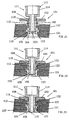
- the mode of operation of the present connecting device for connecting two rod-shaped components 121 and 122, each with a through hole, is shown in longitudinal sections.
- the two components 121, 122 are provided in a manner known per se on both sides at their bore ends with an annular recess 123.
- FIG. 21 shows a first position of the connecting device consisting of the sleeve 101 and the locking element 111.
- the plug-shaped locking element 111 is already inserted into the sleeve 101, as was explained above, and is held there in an inseparable but axially displaceable manner due to the projection 108 of the sleeve 101 and the shoulder 119 of the locking element 111.
- the sleeve 101 by exerting an axial force on the handle 114 of the locking element 111, the sleeve 101 also shifts, since the outer bead 116 of the locking element 111 on the inner annular projection 106 of the sleeve 101 presses, and since the end region of the sleeve 101 having the outer edge bead 105 can be compressed due to the slots 104.
- the sleeve 101 reaches the end position shown in FIG. 22, in which on the one hand the edge bead 105 of the sleeve 101 is elastically latched into the outside recess 123 of the component 121 and on the other hand the flange 103 of the sleeve 101 on the opposite outside of the component 122 rests.
- the components 121 and 122 are connected to one another by the sleeve 101, as is known per se; a separation of the components 121, 122 would, however, disadvantageously be possible with little application of force.
- the locking element 111 is now pressed further into the sleeve 101.
- the outer edge bead 116 of the locking element 111 can slide over the inner projection 106 of the sleeve 101 because the slotted sleeve end can expand radially with its outer edge bead 105 into the recess 123 of the component 121 during this process. Thereafter, as can be seen in FIG. 23, the edge bead 116 reaches the outer side of the inner projection 106 of the sleeve 101, the slotted sleeve end snapping back radially inwards.
- the connecting device for toy components according to the invention can be designed according to the embodiment shown in FIG. 24.
- a connecting device which in turn comprises a sleeve 127 inserted into the bores of the components 125, 126 and a locking element 128 inserted into the sleeve 127.
- the components 125, 126 have annular recesses 129 on both sides of their bore edges.
- the sleeve 127 is again slotted in its end region and provided at its end with an outer edge bead 130 and on the inside with an annular projection 131.
- the locking element 128 has a handle 132 and an outer edge bead 133 at the open end of its cylindrical part.
- the sleeve 127 according to FIG. 24 has a further edge bead 134 which is in the annular recess 129 of the other component 126 lies and therefore performs the same stop function as the flange 103.
- an elastic cap 137 is placed over the plugged unit of the sleeve 127 and the locking element 128, which are axially limited by a shoulder 135 of the locking element 128 and an annular inner projection 136 of the sleeve 127, which is put over for holding on this unit has an edge bead 138 resting on the end region of the sleeve 127 and the handle 132 of the locking device 128.
- the elastic cap 137 can be made of rubber or an elastic plastic.
- the mode of operation of the connecting device shown in FIG. 24 corresponds to the previous explanations with reference to FIGS. 21 to 23.
- the unit of the sleeve 127 and the locking element 128 always remains tightly surrounded by the cap 137, even if the locking element 128 is axially displaced in the sleeve 127 by the distance given by the shoulder 135 and the inner projection 136.
- the unit mentioned is practically completely protected against the ingress of foreign matter between the sleeve 127 and the locking element 128.
- Components to be connected with the connecting device according to the invention in particular toy components, which belong to a kit and which have at least one cylindrical bore of uniform diameter, can of course have practically any design that fits into the kit in question, for example the shapes of prismatic modules of different sizes , Bars, beams, plates, etc.
- M module of the relevant kit
- the rod 140 is not made of full material. Rather, it has a relatively thin partition 142 and a molded, outer edge 143, which determines the thickness of 1/4 M of the rod 140.
- Each bore 141 is defined by a sleeve-shaped, cylindrical part 144 molded onto the partition 142, which is surrounded by an outer reinforcing ring 145.
- the reinforcement rings 145 are connected to one another and to the edge 143 by means of integrally formed reinforcement webs 146, the edge 143, the rings 145 and the webs 146 having outer surfaces on both sides of the partition 142 which lie in the same planes.
- the length of the cylindrical part 144 of each bore 141 is less than the total thickness of 1/4 M of the rod 140 shown, so that there is an annular recess 147 on both ends of the partition 142.
- annular recess 147 is intended for receiving the edge bead 105 of the sleeve 101 of FIG. 15.
- a connecting device In order to connect two rods according to FIG. 25 to one another, a connecting device according to FIG. 21 is used, for example, in which the sleeve part 102 of the sleeve 101 has a length including edge bead 105 of 1/2 M (twice the thickness of each rod of FIG. 25 ) Has. 24, the total length of the sleeve 127 including the two edge beads 130 and 134 is also approximately 1/2 M.
- M module of the kit
- the coupling pin 148 and the four side walls of the block are each provided with a bore 149 or 150, all of which have the same diameter.
- the inner end of the coupling pin 148 projecting into the cavity of the module is provided with an annular recess 151.
- the lateral bores 150 end in the cavity of the module with smooth outer surfaces of an integrally formed ring extension 152.
- Each ring extension 152 is also provided with a rib 153 which extends to the edge of the open side of the module.
- the four ribs 153 on the one hand reinforce the side walls of the module which are somewhat weakened by the bores 150 and at the same time form counter-coupling elements for coupling the module to the coupling pin of another component.
- the openings 154 shown in FIG. 26 are unnecessary or disadvantageous only for manufacturing reasons for the elimination Material collections provided.
- the module of FIGS. 26, 27 is made in one piece from a plastic material.
- the rod 70 according to FIG. 28 differs from the rod 140 according to FIG. 25 only in that four cams 78 are formed in each recess 77, which in the exemplary embodiment shown are in an extension of the reinforcing webs 76. These cams 78 correspond to cams 24 in the embodiment according to FIGS. 7 to 12 and have the same function.
- the parts with the reference numerals 71 to 77 of the rod 70 correspond to the parts with the reference numerals 141 to 147 of the rod 140.
- Two rods 70 can be connected to one another by a connecting device according to FIG. 5 in the manner described with reference to FIGS. 7 to 12.
Landscapes
- Engineering & Computer Science (AREA)
- General Engineering & Computer Science (AREA)
- Mechanical Engineering (AREA)
- Toys (AREA)
- Quick-Acting Or Multi-Walled Pipe Joints (AREA)
- Shafts, Cranks, Connecting Bars, And Related Bearings (AREA)
Claims (13)
- Dispositif de jonction amovible, permettant de réunir au moins deux éléments de jouet (21, 22; 125, 126) à assembler comportant chacun un alésage, ce dispositif comprenant, d'une part, une douille (1, 101) qui est destinée à être introduite dans l'alésage des éléments à assembler (21, 22; 125, 126) et comprend un tronçon de tige cylindrique (2, 102) et, dans l'une de ses parties d'extrémité (4, 104a), des fentes longitudinales (3, 104) permettant d'obtenir une élasticité radiale et qui, à l'extrémité libre de cette partie d'extrémité (4, 104a), comporte un bourrelet périphérique extérieur étroit qui fait sallie radialement et qui sert, après l'introduction de la douille (1, 101) dans les alésages des éléments assemblés (21, 22; 125, 126), à s'accrocher, par complémentarité de formes, derrière l'un des éléments à assembler et, d'autre part, une collerette d'appui (12, 103) située à l'extrémité du tronçon de tige cylindrique (2, 102) qui est située à l'opposé du bourrelet périphérique (5, 105), caractérisé en ce que, dans la douille (1, 101), est placé, d'une manière inamovible, un élément de verrouillage (9, 111) en forme de fiche qui est agencé de manière à pouvoir être déplacé dans deux positions vis-à-vis de la douille (1, 101), d'une façon telle que, dans la première position, un tronçon d'extrémité (14, 116) situé à l'extrémité libre de l'élément de verrouillage (9, 111) vient de l'intérieur au contact de la surface intérieure (8, 106a) de la douille (1, 101) dans la zone du plan diamétral du bourrelet périphérique (5, 105) et que, dans la seconde position, ce tronçon d'extrémité (14, 116) est espacé de la surface intérieure (8, 106a) de la douille (1, 101) dans la zone du plan diamétral du bourrelet périphérique (5, 105).
- Dispositif de jonction suivant la revendication 1, caractérisé en ce qu'une gorge circonférentielle extérieure (6, 107) est ménagée entre le bourrelet périphérique (5, 105) et le tronçon de tige cylindrique (2, 102) et en ce que la longueur axiale de la gorge circonférentielle (6, 107) est inférieure à la longueur axiale du tronçon de tige cylindrique (2, 102) de la douille (1, 101) et supérieure à la longueur axiale du bourrelet périphérique (5, 105).
- Dispositif de jonction suivant la revendication 2, caractérisé en ce que, sur la paroi intérieure de la douille et dans la zone du plan diamétral du bourrelet périphérique (5, 105), est disposée une partie en saillie (8', 106) qui fait saillie radialement vers l'intérieur et sur laquelle, lors du déplacement de l'élément de verrouillage (9, 111), le tronçon d'extrémité (14, 116) glisse de la seconde position à la première position, de sorte que l'élément de verrouillage est immobilisé dans la première position.
- Dispositif de jonction suivant l'une des revendications 1 à 3, caractérisé en ce qu'un élément d'actionnement manuel (11, 114) est réalisé au formage sur l'élément de verrouillage (9, 111), à son extrémité opposée au tronçon d'extrémité (14, 116).
- Dispositif de jonction suivant l'une des revendications 1 à 4, caractérisé en ce que, dans la seconde position de l'élément de verrouillage (9, 111), le bourrelet périphérique (5, 105) fait saillie radialement au-delà du diamètre extérieur du tronçon de tige cylindrique (2, 102) et en ce que, dans la première position de l'élément de verrouillage (9, 111), le tronçon d'extrémité (14, 116) empêche la partie d'extrémité (4, 104a) de la douille (1, 101) de jouer élastiquement dans le sens radial.
- Dispositif de jonction suivant l'une des revendications 1 à 5, caractérisé en ce que l'élément de verrouillage (9) est maintenu dans la douille (1) de façon à pouvoir tourner et sans pouvoir être déplacé axialement au moins dans sa première position et en ce que le tronçon d'extrémité situé à l'extrémité libre de l'élément de verrouillage (9) est constitué de nervures (14) dont le nombre correspond au nombre des fentes longitudinales (3).
- Dispositif de jonction suivant l'une des revendications 4 et 6, caractérisé en ce que l'élément d'actionnement manuel (11) comporte un corps en forme de manchon et des ailes (17) réalisées au formage sur ce corps et en ce que la paroi intérieure cylindrique du corps en forme de manchon est pourvue de sections de gorge annulaire (18) qui sont séparées par des sections (19), plus courtes dans la direction circonférentielle, de la paroi intérieure cylindrique du corps en forme de manchon, d'une façon telle qu'un autre dispositif de jonction identique, comportant une douille (1) et un bourrelet périphérique (5) de cette douille qui est fendu, peut être emboîté et fixé dans le corps en forme de manchon de l'élément d'actionnement manuel (11).
- Dispositif de jonction suivant l'une des revendications 6 et 7, caractérisé en ce que la douille (1) comporte des moyens d'immobilisation en rotation permettant d'assurer un calage en rotation sur un premier élément à assembler (21, 22).
- Dispositif de jonction suivant l'une des revendications 6 à 8, caractérisé en ce que la collerette d'appui (12) est réalisée au formage sur l'élément de verrouillage (9).
- Dispositif de jonction suivant l'une des revendications 1 à 5, caractérisé en ce que l'élément de verrouillage (111) est agencé de façon à pouvoir être déplacé en translation axiale dans la douille (101) et en ce que la collerette d'appui (103) est réalisée au formage sur la douille (101).
- Dispositif de jonction suivant la revendication 10, caractérisé en ce que l'élément de verrouillage (111) est pourvu d'un épaulement annulaire extérieur (119) et la douille (101) est pourvue d'un épaulement intérieur (108) correspondant, afin de réunir l'élément de verrouillage (111) à la douille (101) d'une manière inamovible, en permettant toutefois un déplacement en translation axial.
- Dispositif de jonction suivant l'une des revendications 10 et 11, caractérisé en ce qu'un capuchon (137) en matière élastique et de faible épaisseur est enfilé par-dessus la douille (127), ce capuchon (137) assurant l'étanchéité de l'élément de verrouillage (128) à sa périphérie et sur l'extrémité de la douille qui comporte les fentes longitudinales.
- Elément de jouet à assembler, avec dispositif de jonction séparable suivant l'une des revendication 6 à 9, comprenant au moins un alésage cylindrique (71), destiné à recevoir la douille cylindrique (1) du dispositif de jonction, et des zones marginales (77) de l'alésage cylindrique (71) destinées à recevoir le bourrelet périphérique (5) de la douille (1) du dispositif de jonction, caractérisé en ce que l'élément à assembler (21, 22, 70) comporte des moyens (24, 78) de venue en prise sur la douille (1) du dispositif de jonction lorsqu'elle est introduite dans l'alésage cylindrique de l'élément à assembler, ces moyens de venue en prise (24, 78) permettant un déplacement axial de la douille (1) dans l'alésage cylindrique (71), mais bloquant un mouvement de rotation de la douille (1) lorsqu'elle est totalement introduite dans l'alésage cylindrique (71), en ce que, comme moyens de venue en prise, est réalisé au formage, sur le bord de l'alésage cylindrique (71), au moins un bossage (24, 78) qui fait saillie axialement et s'étend radialement vers l'extérieur et en ce que, sur le bord de l'alésage cylindrique, l'élément à assembler est pourvu d'un épaulement annulaire radialement extérieur (23, 77) servant à recevoir le bourrelet périphérique (5) de la douille (1), le bossage (24, 78) étant réalisé au formage sur l'épaulement annulaire (23, 77).
Applications Claiming Priority (3)
| Application Number | Priority Date | Filing Date | Title |
|---|---|---|---|
| CH679/89 | 1989-02-24 | ||
| CH67989 | 1989-02-24 | ||
| PCT/CH1990/000037 WO1990009827A1 (fr) | 1989-02-24 | 1990-02-19 | Dispositif de liaison liberable pour elements de jeux de construction |
Publications (2)
| Publication Number | Publication Date |
|---|---|
| EP0413012A1 EP0413012A1 (fr) | 1991-02-20 |
| EP0413012B1 true EP0413012B1 (fr) | 1994-06-01 |
Family
ID=4192637
Family Applications (2)
| Application Number | Title | Priority Date | Filing Date |
|---|---|---|---|
| EP90902756A Expired - Lifetime EP0413009B1 (fr) | 1989-02-24 | 1990-02-19 | Element de construction, notamment pour jeux de construction |
| EP90902996A Expired - Lifetime EP0413012B1 (fr) | 1989-02-24 | 1990-02-19 | Dispositif de liaison liberable pour elements de jeux de construction |
Family Applications Before (1)
| Application Number | Title | Priority Date | Filing Date |
|---|---|---|---|
| EP90902756A Expired - Lifetime EP0413009B1 (fr) | 1989-02-24 | 1990-02-19 | Element de construction, notamment pour jeux de construction |
Country Status (10)
| Country | Link |
|---|---|
| US (1) | US5304086A (fr) |
| EP (2) | EP0413009B1 (fr) |
| JP (2) | JP2771035B2 (fr) |
| AT (2) | ATE81025T1 (fr) |
| AU (2) | AU5087790A (fr) |
| DE (2) | DE59000330D1 (fr) |
| DK (2) | DK0413009T3 (fr) |
| ES (2) | ES2034858T3 (fr) |
| HK (1) | HK155695A (fr) |
| WO (2) | WO1990009828A1 (fr) |
Families Citing this family (41)
| Publication number | Priority date | Publication date | Assignee | Title |
|---|---|---|---|---|
| DK172267B1 (da) * | 1991-11-06 | 1998-02-16 | Lego As | Legetøjsbyggesæt og byggeelementer dertil |
| US5947787A (en) * | 1997-09-24 | 1999-09-07 | Parvia Corporation | Modular lattice substructure for a toy building set |
| US6129605A (en) * | 1997-09-24 | 2000-10-10 | Parvia Corporation | Modular base units for a toy building set |
| US5924905A (en) * | 1997-09-24 | 1999-07-20 | Parvia Corporation | Modular terrain for a toy building set |
| US5951356A (en) * | 1997-10-27 | 1999-09-14 | Parvia Corporation | Modular lattice substructure for a toy building set having columns and foundations |
| US5993283A (en) * | 1997-09-30 | 1999-11-30 | Parvia Corporation | Modular buildings for a toy building set |
| US6102770A (en) * | 1997-10-03 | 2000-08-15 | Parvia Corporation | Toy vehicular electromechanical guidance apparatus |
| US5865661A (en) * | 1997-10-03 | 1999-02-02 | Parvia Corporation | Toy vehicular drive apparatus |
| US6007401A (en) * | 1997-10-03 | 1999-12-28 | Parvia Corporation | Optoelectric remote control apparatus for guiding toy vehicles |
| US6012957A (en) * | 1997-10-27 | 2000-01-11 | Parvia Corporation | Single beam optoelectric remote control apparatus for control of toys |
| NL1007436C2 (nl) * | 1997-11-04 | 1999-05-06 | Wild Design Holding Gmbh | Modulair bouwsysteem met draaikoppeling. |
| TW501496U (en) * | 1998-10-14 | 2002-09-01 | Interlego Ag | A toy gear box and a gear housing therefor |
| US6190362B1 (en) | 1999-03-22 | 2001-02-20 | Bracco Diagnostics, Inc. | Plunger rod |
| FR2808848A1 (fr) * | 2000-05-10 | 2001-11-16 | Ensam Ecole Nationale Superieu | Dispositif d'immobilisation d'une piece sur un arbre |
| WO2004071607A2 (fr) * | 2003-02-07 | 2004-08-26 | Gracewood, Inc. | Elements de construction de modele interconnectables |
| JP4446794B2 (ja) | 2004-05-10 | 2010-04-07 | ダイキョーニシカワ株式会社 | 部材の結合構造 |
| USD517128S1 (en) * | 2004-12-29 | 2006-03-14 | Kwan-Young Kim | Assembly block |
| USD516135S1 (en) * | 2004-12-29 | 2006-02-28 | Kwan-Young Kim | Assembly block |
| JP4864908B2 (ja) * | 2007-01-12 | 2012-02-01 | ロボティス カンパニー,リミテッド | 弾性締結具及びこれを用いたアクチュエータモジュール |
| US7950637B2 (en) * | 2007-07-13 | 2011-05-31 | Eagle Fan | Adjustable holding apparatus |
| US8210898B2 (en) * | 2009-02-17 | 2012-07-03 | Parchmint, Inc. | Pivotally manipulable toy |
| BR112015004978B1 (pt) * | 2012-09-11 | 2021-06-08 | Lego A/S | conjunto de construção de brinquedo |
| DE102013001528B3 (de) | 2013-01-29 | 2013-09-26 | Hubert Volk | Spielzeugbausatz |
| US9737826B2 (en) | 2013-03-10 | 2017-08-22 | Pai-Chen Cheng | Pairing block set and toy block thereof |
| DE102013211560B4 (de) * | 2013-06-19 | 2023-09-28 | BSH Hausgeräte GmbH | Baukasten zum wahlweisen Herstellen eines Leichtlaufauszugs oder eines Schienenauszugs für eine Spülgutaufnahme einer Geschirrspülmaschine, Spülbehälter für eine Geschirrspülmaschine und Geschirrspülmaschine |
| JP5711864B2 (ja) * | 2013-07-14 | 2015-05-07 | 理 藤井 | 組合せ定規 |
| US8991131B1 (en) * | 2014-01-29 | 2015-03-31 | Baojing Lu | Construction system for building curved structures |
| CN103953626B (zh) * | 2014-04-30 | 2016-06-15 | 芮秋婷 | 一种管套管式固定管座 |
| KR101563632B1 (ko) * | 2014-07-22 | 2015-11-06 | 주식회사 아키토이 | 완구용 조립블록 |
| KR101758628B1 (ko) | 2015-08-25 | 2017-07-18 | 주식회사 로보로보 | 완구용 결합유닛 |
| US10159905B2 (en) * | 2016-09-01 | 2018-12-25 | Gracewood Management, Inc. | Construction toy set of connectable and positionable elements |
| WO2018060908A1 (fr) * | 2016-09-28 | 2018-04-05 | Bodak Blocks Limited | Bloc de construction et ensembles de blocs de construction |
| USD811202S1 (en) * | 2017-01-17 | 2018-02-27 | Spectrum Diversified Designs, Llc | Tool holder |
| KR200488588Y1 (ko) * | 2017-02-23 | 2019-05-21 | 남해원 | 블럭용 힌지 구조물 |
| CN114377413A (zh) * | 2017-03-20 | 2022-04-22 | 贝尔合控(深圳)科技有限责任公司 | 玩具构造套件 |
| WO2018208202A1 (fr) * | 2017-05-12 | 2018-11-15 | Strawbees Ab | Connecteur et système comprenant une pluralité de tels connecteurs |
| KR102007717B1 (ko) * | 2017-12-27 | 2019-08-06 | 윤이식 | 조립형 완구 프레임 |
| USD940795S1 (en) * | 2020-01-22 | 2022-01-11 | Costas Sisamos | Snap-lock construction toy beam unit |
| GB2600125A (en) * | 2020-10-21 | 2022-04-27 | Limbs & Things Ltd | Improvements in or relating to a cover |
| US11813544B2 (en) * | 2021-10-04 | 2023-11-14 | Insite Global Holdings | Modular toy structure |
| KR102557296B1 (ko) * | 2022-11-08 | 2023-07-20 | 구자민 | 비눗방울 놀이구 |
Family Cites Families (18)
| Publication number | Priority date | Publication date | Assignee | Title |
|---|---|---|---|---|
| FR541757A (fr) * | 1921-09-28 | 1922-08-01 | Nouveau mode d'assemblage rigide des lamelles servant à la composition de jouets dits : de construction, etc. | |
| US1860627A (en) * | 1927-10-06 | 1932-05-31 | John Q Sherman | Toy |
| US2226819A (en) * | 1939-03-06 | 1940-12-31 | Conn Ltd C G | Method of making adjustable joints |
| US3112547A (en) * | 1960-11-15 | 1963-12-03 | Hartwell Corp | Fastener |
| DE1400209B2 (de) * | 1960-09-08 | 1970-05-06 | Illinois Tool Works Inc., Chicago, 111. (V.St.A.) | Spreiznietartiges Befestigungselement |
| US3277601A (en) * | 1964-01-23 | 1966-10-11 | John W Ryan | Doll having an angularly adjustable limb |
| GB1187430A (en) * | 1967-08-22 | 1970-04-08 | Painton & Co Ltd | Improvements in or relating to Quick Release Fasteners and Components Combined with such Fasteners |
| CA855914A (en) * | 1968-02-23 | 1970-11-17 | A. Mackenzie James | Releasable reusable expanding fastener |
| GB1270540A (en) * | 1968-06-19 | 1972-04-12 | Peter George England | Improvements in or relating to securing devices |
| DE2115564A1 (de) * | 1971-03-31 | 1972-10-12 | Trix Mangold GmbH & Co, 8500 Nurn berg | Verbindungselement fur die Teile von Konstruktionsbauspielzeug |
| DE2125734A1 (de) * | 1971-05-25 | 1972-12-07 | Frevel E | Klemmknopf zum Befestigen von Andruckleisten in Kunststoffprofilen |
| US3979855A (en) * | 1973-06-16 | 1976-09-14 | Otto Schmidt | Construction toy |
| DE2335023A1 (de) * | 1973-07-10 | 1975-02-06 | Itw Ateco Gmbh | Befestigungselement |
| US3918130A (en) * | 1974-01-25 | 1975-11-11 | Hartwell Corp | Initially one piece removable fastener |
| US3964364A (en) * | 1975-04-17 | 1976-06-22 | Hartwell Corporation | Initially single piece rotatable fastener |
| DK150448C (da) * | 1980-11-25 | 1987-10-12 | Interlego Ag | Kobling, bestaaende af et par samleled til udloeselig sammenkobling af stangformede konstruktionselementer, saerlig legetoejselementer, i forskellige indbyrdes vinkelstillinger |
| DK153289C (da) * | 1981-09-14 | 1988-12-05 | Lego As | Samleboesning |
| US4773503A (en) * | 1987-09-11 | 1988-09-27 | Robert L. Pease | Ladder hinge |
-
1990
- 1990-02-19 ES ES199090902756T patent/ES2034858T3/es not_active Expired - Lifetime
- 1990-02-19 AT AT90902756T patent/ATE81025T1/de not_active IP Right Cessation
- 1990-02-19 DE DE9090902756T patent/DE59000330D1/de not_active Expired - Fee Related
- 1990-02-19 JP JP2502926A patent/JP2771035B2/ja not_active Expired - Lifetime
- 1990-02-19 ES ES90902996T patent/ES2053178T3/es not_active Expired - Lifetime
- 1990-02-19 EP EP90902756A patent/EP0413009B1/fr not_active Expired - Lifetime
- 1990-02-19 AU AU50877/90A patent/AU5087790A/en not_active Abandoned
- 1990-02-19 WO PCT/CH1990/000038 patent/WO1990009828A1/fr active IP Right Grant
- 1990-02-19 DK DK90902756.7T patent/DK0413009T3/da active
- 1990-02-19 WO PCT/CH1990/000037 patent/WO1990009827A1/fr active IP Right Grant
- 1990-02-19 JP JP2503160A patent/JP2773977B2/ja not_active Expired - Lifetime
- 1990-02-19 DE DE59005895T patent/DE59005895D1/de not_active Expired - Fee Related
- 1990-02-19 DK DK90902996.9T patent/DK0413012T3/da active
- 1990-02-19 AT AT90902996T patent/ATE106261T1/de not_active IP Right Cessation
- 1990-02-19 AU AU50427/90A patent/AU5042790A/en not_active Abandoned
- 1990-02-19 EP EP90902996A patent/EP0413012B1/fr not_active Expired - Lifetime
-
1992
- 1992-06-15 US US07/899,012 patent/US5304086A/en not_active Expired - Fee Related
-
1995
- 1995-09-28 HK HK155695A patent/HK155695A/xx not_active IP Right Cessation
Also Published As
| Publication number | Publication date |
|---|---|
| WO1990009827A1 (fr) | 1990-09-07 |
| JP2773977B2 (ja) | 1998-07-09 |
| JPH03504344A (ja) | 1991-09-26 |
| AU5087790A (en) | 1990-09-26 |
| JP2771035B2 (ja) | 1998-07-02 |
| ATE106261T1 (de) | 1994-06-15 |
| ES2034858T3 (es) | 1993-04-01 |
| EP0413012A1 (fr) | 1991-02-20 |
| HK155695A (en) | 1995-10-06 |
| WO1990009828A1 (fr) | 1990-09-07 |
| DK0413009T3 (da) | 1992-11-02 |
| JPH03504345A (ja) | 1991-09-26 |
| EP0413009A1 (fr) | 1991-02-20 |
| DK0413012T3 (da) | 1994-06-20 |
| DE59000330D1 (de) | 1992-11-05 |
| ATE81025T1 (de) | 1992-10-15 |
| AU5042790A (en) | 1990-09-26 |
| EP0413009B1 (fr) | 1992-09-30 |
| DE59005895D1 (de) | 1994-07-07 |
| US5304086A (en) | 1994-04-19 |
| ES2053178T3 (es) | 1994-07-16 |
Similar Documents
| Publication | Publication Date | Title |
|---|---|---|
| EP0413012B1 (fr) | Dispositif de liaison liberable pour elements de jeux de construction | |
| EP0662200B1 (fr) | Dispositif pour relier au moins deux elements | |
| DE29701099U1 (de) | Stiftförmiges Halteelement für ein orthopädisches Haltesystem | |
| EP1501453A1 (fr) | Implant reglable en hauteur destine a etre insere entre des vertebres et outil de manipulation | |
| WO2001092667A1 (fr) | Serrure a barres pour systeme de fermeture | |
| WO1993018678A1 (fr) | Dispositif a pression pour le blocage de lacets | |
| EP0713558A1 (fr) | Systeme de fermeture, notamment pour automobiles et equipements de batiments | |
| DE4006707C2 (de) | Vorreiberverschluß | |
| DE3511070A1 (de) | Vorrichtung zum loesbaren verbinden zweier mit fluchtenden oeffnungen versehener bauteile | |
| DE29511547U1 (de) | Vorrichtung zur axial unverschieblichen, lösbaren Befestigung einer Handhabe an einem Lagerteil, insbesondere für Türdrücker, Fenstergriffe o.dgl. | |
| DE3202313A1 (de) | Verriegelungsanordnung fuer eine kupplung | |
| DE19501882C2 (de) | Medizinisches Instrument | |
| DE2056723A1 (de) | Türschild oder Rosette | |
| EP2156060B1 (fr) | Dispositif de fixation permettant d'assembler un profilé et un contre-profilé de façon libérable | |
| EP0204223B1 (fr) | Unité de construction à bouton-poussoir | |
| EP0413964B1 (fr) | Mécanisme pour actionner le verrou d'une serrure | |
| EP0791759A1 (fr) | Boulon à connexion rapide | |
| DE3424075A1 (de) | Steckverbinder | |
| EP0952282A1 (fr) | Serrure de porte avec manipulation et clé | |
| EP0413011B1 (fr) | Dispositif de liaison pour des elements de jeux de construction | |
| DE2530666C2 (de) | Druck-Drehzylinderschloß | |
| DE2800374A1 (de) | Drehzylinderschloss mit schiebestiften | |
| DE3512425A1 (de) | Hohlwanddose fuer elektrische installationseinrichtungen, insbesondere schalter, steckdosen od.dgl. | |
| DE3518866C1 (de) | Bolzenteile zur Bildung eines selbstsichernden Sperrbolzens | |
| DE102020117657A1 (de) | Verbindungssystem |
Legal Events
| Date | Code | Title | Description |
|---|---|---|---|
| PUAI | Public reference made under article 153(3) epc to a published international application that has entered the european phase |
Free format text: ORIGINAL CODE: 0009012 |
|
| 17P | Request for examination filed |
Effective date: 19901012 |
|
| AK | Designated contracting states |
Kind code of ref document: A1 Designated state(s): AT BE CH DE DK ES FR GB IT LI LU NL SE |
|
| 17Q | First examination report despatched |
Effective date: 19920218 |
|
| GRAA | (expected) grant |
Free format text: ORIGINAL CODE: 0009210 |
|
| ITF | It: translation for a ep patent filed | ||
| AK | Designated contracting states |
Kind code of ref document: B1 Designated state(s): AT BE CH DE DK ES FR GB IT LI LU NL SE |
|
| REF | Corresponds to: |
Ref document number: 106261 Country of ref document: AT Date of ref document: 19940615 Kind code of ref document: T |
|
| REG | Reference to a national code |
Ref country code: DK Ref legal event code: T3 |
|
| GBT | Gb: translation of ep patent filed (gb section 77(6)(a)/1977) |
Effective date: 19940607 |
|
| REF | Corresponds to: |
Ref document number: 59005895 Country of ref document: DE Date of ref document: 19940707 |
|
| REG | Reference to a national code |
Ref country code: ES Ref legal event code: FG2A Ref document number: 2053178 Country of ref document: ES Kind code of ref document: T3 |
|
| ET | Fr: translation filed | ||
| EAL | Se: european patent in force in sweden |
Ref document number: 90902996.9 |
|
| PLBE | No opposition filed within time limit |
Free format text: ORIGINAL CODE: 0009261 |
|
| STAA | Information on the status of an ep patent application or granted ep patent |
Free format text: STATUS: NO OPPOSITION FILED WITHIN TIME LIMIT |
|
| 26N | No opposition filed | ||
| PGFP | Annual fee paid to national office [announced via postgrant information from national office to epo] |
Ref country code: FR Payment date: 20000112 Year of fee payment: 11 |
|
| PGFP | Annual fee paid to national office [announced via postgrant information from national office to epo] |
Ref country code: DK Payment date: 20000113 Year of fee payment: 11 Ref country code: CH Payment date: 20000113 Year of fee payment: 11 Ref country code: AT Payment date: 20000113 Year of fee payment: 11 |
|
| PGFP | Annual fee paid to national office [announced via postgrant information from national office to epo] |
Ref country code: SE Payment date: 20000119 Year of fee payment: 11 |
|
| PGFP | Annual fee paid to national office [announced via postgrant information from national office to epo] |
Ref country code: LU Payment date: 20000120 Year of fee payment: 11 Ref country code: GB Payment date: 20000120 Year of fee payment: 11 |
|
| PGFP | Annual fee paid to national office [announced via postgrant information from national office to epo] |
Ref country code: DE Payment date: 20000127 Year of fee payment: 11 |
|
| PGFP | Annual fee paid to national office [announced via postgrant information from national office to epo] |
Ref country code: ES Payment date: 20000208 Year of fee payment: 11 Ref country code: BE Payment date: 20000208 Year of fee payment: 11 |
|
| PGFP | Annual fee paid to national office [announced via postgrant information from national office to epo] |
Ref country code: NL Payment date: 20000229 Year of fee payment: 11 |
|
| PG25 | Lapsed in a contracting state [announced via postgrant information from national office to epo] |
Ref country code: LU Free format text: LAPSE BECAUSE OF NON-PAYMENT OF DUE FEES Effective date: 20010219 Ref country code: GB Free format text: LAPSE BECAUSE OF NON-PAYMENT OF DUE FEES Effective date: 20010219 Ref country code: DK Free format text: LAPSE BECAUSE OF NON-PAYMENT OF DUE FEES Effective date: 20010219 Ref country code: AT Free format text: LAPSE BECAUSE OF NON-PAYMENT OF DUE FEES Effective date: 20010219 |
|
| PG25 | Lapsed in a contracting state [announced via postgrant information from national office to epo] |
Ref country code: SE Free format text: LAPSE BECAUSE OF NON-PAYMENT OF DUE FEES Effective date: 20010220 Ref country code: ES Free format text: LAPSE BECAUSE OF NON-PAYMENT OF DUE FEES Effective date: 20010220 |
|
| PG25 | Lapsed in a contracting state [announced via postgrant information from national office to epo] |
Ref country code: LI Free format text: LAPSE BECAUSE OF NON-PAYMENT OF DUE FEES Effective date: 20010228 Ref country code: CH Free format text: LAPSE BECAUSE OF NON-PAYMENT OF DUE FEES Effective date: 20010228 Ref country code: BE Free format text: LAPSE BECAUSE OF NON-PAYMENT OF DUE FEES Effective date: 20010228 |
|
| BERE | Be: lapsed |
Owner name: LEGO A/S Effective date: 20010228 |
|
| PG25 | Lapsed in a contracting state [announced via postgrant information from national office to epo] |
Ref country code: NL Free format text: LAPSE BECAUSE OF NON-PAYMENT OF DUE FEES Effective date: 20010901 |
|
| REG | Reference to a national code |
Ref country code: CH Ref legal event code: PL |
|
| EUG | Se: european patent has lapsed |
Ref document number: 90902996.9 |
|
| GBPC | Gb: european patent ceased through non-payment of renewal fee |
Effective date: 20010219 |
|
| REG | Reference to a national code |
Ref country code: DK Ref legal event code: EBP |
|
| PG25 | Lapsed in a contracting state [announced via postgrant information from national office to epo] |
Ref country code: FR Free format text: LAPSE BECAUSE OF NON-PAYMENT OF DUE FEES Effective date: 20011031 |
|
| NLV4 | Nl: lapsed or anulled due to non-payment of the annual fee |
Effective date: 20010901 |
|
| REG | Reference to a national code |
Ref country code: FR Ref legal event code: ST |
|
| PG25 | Lapsed in a contracting state [announced via postgrant information from national office to epo] |
Ref country code: DE Free format text: LAPSE BECAUSE OF NON-PAYMENT OF DUE FEES Effective date: 20011201 |
|
| REG | Reference to a national code |
Ref country code: ES Ref legal event code: FD2A Effective date: 20020916 |
|
| PG25 | Lapsed in a contracting state [announced via postgrant information from national office to epo] |
Ref country code: IT Free format text: LAPSE BECAUSE OF NON-PAYMENT OF DUE FEES;WARNING: LAPSES OF ITALIAN PATENTS WITH EFFECTIVE DATE BEFORE 2007 MAY HAVE OCCURRED AT ANY TIME BEFORE 2007. THE CORRECT EFFECTIVE DATE MAY BE DIFFERENT FROM THE ONE RECORDED. Effective date: 20050219 |