EP0410190B1 - Vase - Google Patents
Vase Download PDFInfo
- Publication number
- EP0410190B1 EP0410190B1 EP90113013A EP90113013A EP0410190B1 EP 0410190 B1 EP0410190 B1 EP 0410190B1 EP 90113013 A EP90113013 A EP 90113013A EP 90113013 A EP90113013 A EP 90113013A EP 0410190 B1 EP0410190 B1 EP 0410190B1
- Authority
- EP
- European Patent Office
- Prior art keywords
- stem
- vase
- vase according
- screw collar
- outside
- Prior art date
- Legal status (The legal status is an assumption and is not a legal conclusion. Google has not performed a legal analysis and makes no representation as to the accuracy of the status listed.)
- Expired - Lifetime
Links
Images

Classifications
-
- A—HUMAN NECESSITIES
- A47—FURNITURE; DOMESTIC ARTICLES OR APPLIANCES; COFFEE MILLS; SPICE MILLS; SUCTION CLEANERS IN GENERAL
- A47G—HOUSEHOLD OR TABLE EQUIPMENT
- A47G7/00—Flower holders or the like
- A47G7/02—Devices for supporting flower-pots or cut flowers
- A47G7/06—Flower vases
-
- A—HUMAN NECESSITIES
- A47—FURNITURE; DOMESTIC ARTICLES OR APPLIANCES; COFFEE MILLS; SPICE MILLS; SUCTION CLEANERS IN GENERAL
- A47G—HOUSEHOLD OR TABLE EQUIPMENT
- A47G7/00—Flower holders or the like
- A47G7/02—Devices for supporting flower-pots or cut flowers
- A47G7/06—Flower vases
- A47G2007/066—Flower vases adaptable for flowers of differing heights, e.g. telescopic flower vases
Definitions
- the invention relates to a vase according to the preamble of the main claim.
- a flower vase is known from DE 84 26 162-U1, which consists of an upper part and a foot part, the upper part and foot part being detachably connected to one another and forming a flower vase unit.
- the overall height of the flower vase can be adjusted as desired by screwing or pushing the upper part more or less into the foot part.
- the upper part and the lower part can be connected to one another by a shrink fit.
- a perfect seal between the upper part and lower part is also not achieved by a shrink fit, which ensures that the two components move against each other. It is therefore not possible with this known vase to fill the water into the vase so far that the water level is above the connection point between the foot part and the upper part. But especially with long-stemmed and therefore large flowers, it is a disadvantage if the water is only contained in the foot part, since you are just at Outdoor vases in particular strive to accommodate as much water as possible for the flowers in the vase.
- the older application DE 38 26 334 C1 relates to an outdoor vase, in which the upper part and foot part are provided with intermeshing thread areas. In addition, a seal is provided in a thread-free area.
- This arrangement enables the formation of a two-part vase, in which the upper part can be adjusted upwards far from the foot part, and the entire vase thus formed can nevertheless be filled completely with water. The manufacture and formation of the thread areas is expensive.
- the invention has for its object to design the generic vase according to DE 84 26 162-U1 so that the greatest possible adjustment between the upper part and foot part is possible with the simplest means, on the other hand, a complete seal is brought about in the connection area of the two components, so that this vase can be filled with water up to the upper edge of the upper part even when the upper part is fully extended.
- the construction should be as simple as possible so that an inexpensive vase can be produced in large series.
- This combined movement or loading of the sealing ring is achieved according to a first embodiment in that a circumferential pressure surface which widens obliquely from top to bottom is provided in the inside of the coupling ring, so that a receiving space for the sealing ring is simultaneously created by this pressure surface.
- the required downward movement of the collar ring to fix the seal on the outside of the upper part and on the top of the socket can be achieved by a thread, i. H. an internal thread on the inside of the collar ring and an external thread on the outside of the socket, or by a bayonet lock, so that the axially directed movement z. B. must be applied by hand to the coupling ring.
- the procedure is such that the upper edge region of the foot part is designed to be deformable, a sealing ring is arranged on the inside of the upper edge region of the foot part and the coupling ring is designed in such a way that it screws the upper part when screwed in Edge area of the foot part of the vase presses inwards.
- This can be done in the simplest way that in particular the internal thread of the coupling ring widens conically from top to bottom, so that when screwing onto the external thread provided on the outside of the foot part, the upper edge region of the foot part is pressed onto the outside of the inner part.
- the procedure can also be such that the external thread of the foot part widens from bottom to top and the internal thread of the coupling ring is cylindrical. Then the union ring must be screwed onto the external thread of the foot section from bottom to top.
- a two-part vase which consists of a foot part 1 and an upper part 2.
- serrations or skewers can be provided so that the vase can also be set up permanently as an outdoor vase.
- the upper part 2 is designed as a cylinder body, the top and is open at the bottom, while the foot part 1 is closed on its bottom side and has an opening in its upper area for receiving the upper part 2. This opening is delimited by an axially aligned connecting piece 9, which has an external thread 7 on its outside.
- the upper part 2 is surrounded by a coupling ring 3, which is made, for example, of plastic and is designed to widen conically from top to bottom on its inside, so that a space 6 is created in which a pressure surface 5 is formed.
- a coupling ring 3 which is made, for example, of plastic and is designed to widen conically from top to bottom on its inside, so that a space 6 is created in which a pressure surface 5 is formed.
- the printing surface 5 can also be provided with an elastic pad.
- a bayonet lock can also be used.
- a plurality of seals can also be arranged one above the other be provided.
- the union ring has a pressure surface in its upper, inner area, which allows the fixing of the upper part 2 via the union ring 3 in the foot part 1, and that the seal via a separate, movable sealing ring or also from one the union ring 3 elaborated stop, which acts as a sealing stop and interacts with the upper edge of the connector 9, takes place.
- Fig. 1 the vase is shown so that the foot part 1 as a spherical container forms the lower part and the upper part 2 is adjustable as a cylindrical component in this foot part 1.
- the vase can also be designed the other way around, i.e. H. that the actual foot part is cylindrical, is naturally closed at its bottom part and that the spherical component forms the top part, is open at the top and thus, for example, provides a larger opening for receiving a bouquet of flowers.
- the upper part is then also a cylinder body which is open at the top and bottom, but which is bulged.
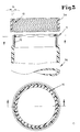
- a foot part 1a is provided, which cooperates with an upper part, not shown in the drawing.
- an external thread 11 is provided in the upper region, the outer circumference of which, viewed in the axial direction of the foot part 1 a, is cylindrical.
- a sealing ring 12 is arranged on the inside of the upper region of the foot part 1a and the upper region of the foot part 1a is designed to be deformable in that lamellae 14 are created by means of individual axially aligned slots.
- the sealing ring 12 can have different thicknesses and thereby compensate for tolerances.
- the deformability of the upper region of the foot part 1 a can also be achieved by appropriate choice of material.
- a coupling ring 3a which has an internal thread 10, works together with the upper part of the foot part 1a.
- this internal thread 10 has a conical design, i. H. extends from top to bottom in the axial direction of the foot part 1a or the upper part.
Description
- Die Erfindung bezieht sich auf eine Vase gemäß dem Oberbegriff des Hauptanspruches.
- Aus dem DE 84 26 162-U1 ist eine Blumenvase bekannt, die aus einem Oberteil und einem Fußteil besteht, wobei Oberteil und Fußteil lösbar miteinander verbunden sind und eine Blumenvaseneinheit bilden. Die Gesamthöhe der Blumenvase kann nach Wunsch verstellt werden, indem das Oberteil mehr oder weniger in das Fußteil eingeschraubt oder eingeschoben wird. Hierbei können das Oberteil und das Unterteil durch einen Schrumpfsitz miteinander verbunden sein. Eine einwandfreie Abdichtung zwischen Oberteil und Unterteil wird auch durch einen Schrumpfsitz, der ein Verschieben der beiden Bauteile gegeneinander gewährleistet, nicht erreicht. Es ist also bei dieser bekannten Vase nicht möglich, das Wasser so weit in die Vase einzufüllen, daß der Wasserspiegel oberhalb der Verbindungsstelle zwischen Fußteil und Oberteil steht. Gerade aber bei langstengeligen und damit großen Blumen ist es aber ein Nachteil, wenn nur im Fußteil das Wasser enthalten ist, da man gerade bei insbesondere Freilandvasen bestrebt ist, möglichst viel Wasservorrat für die Blumen in der Vase unterzubringen.
- Die ältere Anmeldung DE 38 26 334 C1 betrifft eine Freilandvase, bei welcher Oberteil und Fußteil mit miteinander kämmenden Gewindebereichen versehen sind. Außerdem ist eine Dichtung in einem gewindefreien Bereich vorgesehen. Diese Anordnung ermöglicht die Ausbildung einer zweiteiligen Vase, bei welcher das Oberteil weit aus dem Fußteil heraus nach oben verstellt werden kann und wobei trotzdem die so gebildete Gesamtvase voll mit Wasser gefüllt werden kann. Die Herstellung und Ausbildung der Gewindebereiche ist aber kostenaufwendig.
- Der Erfindung liegt die Aufgabe zugrunde, die gattungsbildende Vase gemäß dem DE 84 26 162-U1 so auszugestalten, daß mit einfachsten Mitteln ein möglichst weitgehendes Verstellen zwischen Oberteil und Fußteil möglich ist, andererseits eine vollständige Abdichtung im Verbindungsbereich der beiden Bauteile herbeigeführt wird, so daß diese Vase auch bei voll ausgezogenem Oberteil bis zum oberen Rand des Oberteils mit Wasser gefüllt werden kann. Hierbei soll die Konstruktion möglichst einfach sein, so daß großserienmäßig eine kostengünstige Vase erstellt werden kann.
- Diese der Erfindung zugrundeliegende Aufgabe wird durch die Lehre des Hauptanspruches gelöst.
- Vorteilhafte Ausgestaltungen sind in den Unteransprüchen angegeben.
- Mit anderen Worten ausgedrückt, wird eine Verbindung zwischen Oberteil und Fußteil vorgeschlagen, bei welcher durch einen Überwurfring eine Dichtung durch diesen Überwurfring an die Außenseite des Oberteiles und an die obere Randkante des Fußteiles aufgepreßt wird. Hierdurch wird mit einer Dichtung erreicht, daß einerseits eine gute Abdichtung zwischen dem Inneren des Fußteiles und der Außenseite des Oberteiles herbeigeführt wird, andererseits legt dieser Dichtring gleichzeitig das Oberteil gegen Bewegungen in dessen axialer Richtung fest.
- Diese kombinierte Bewegung oder Beaufschlagung des Dichtringes wird gemäß einer ersten Ausführungsform dadurch erreicht, daß im Inneren des Überwurfringes eine schräg sich von oben nach unten erweiternde umlaufende Druckfläche vorgesehen ist, so daß durch diese Druckfläche gleichzeitig ein Aufnahmeraum für den Dichtring geschaffen wird. Die erforderliche, nach unten gerichtete Bewegung des Überwurfringes zum Festlegen der Dichtung an der Außenseite des Oberteiles und auf der Oberseite des Stutzens kann durch ein Gewinde erreicht werden, d. h. ein Innengewinde auf der Innenseite des Überwurfringes und ein Außengewinde auf der Außenseite des Stutzens, oder durch einen Bajonettverschluß, so daß dann die axial gerichtete Bewegung z. B. von Hand auf den Überwurfring aufgebracht werden muß.
- Gemäß einer anderen Ausführungsform der Erfindung wird so vorgegangen, daß der obere Randbereich des Fußteiles verformbar ausgebildet ist, auf der Innenseite des oberen Randbereiches des Fußteiles ein Dichtring angeordnet wird und der Überwurfring so gestaltet ist, daß er beim Einschrauben den oberen Randbereich des Fußteiles der Vase nach innen preßt. Dies kann in einfachster Weise dadurch erfolgen, daß insbesondere das Innengewinde des Überwurfringes sich konisch von oben nach unten erweitert, so daß beim Aufschrauben auf das an der Außenseite des Fußteiles vorgesehene Außengewinde der obere Randbereich des Fußteiles auf die Außenseite des Innenteiles gepreßt wird.
- Gemäß einer anderen Ausführungsform kann auch so vorgegangen werden, daß das Außengewinde des Fußteiles sich von unten nach oben erweitert und das Innengewinde des Überwurfringes zylindrisch ausgebildet ist. Dann muß aber der Überwurfring von unten nach oben auf das Außengewinde des Fußteiles aufgeschraubt werden.
- Ausführungsbeispiele der Erfindung werden nachfolgend anhand der Zeichnungen erläutert. Die Zeichnungen zeigen dabei in
- Fig. 1
- einen Schnitt durch eine erste Ausführungsform, in
- Fig. 2
- einen Schnitt gemäß der Linie 2 - 2 in Fig. 1 und in
- Fig. 3
- einen Schnitt durch eine abgeänderte Ausführungsform.
- In den Fig. 1 und 2 ist eine doppelteilige Vase dargestellt, die aus einem Fußteil 1 und einem Oberteil 2 besteht. An der Unterseite des Fußteiles 1 können Zacken oder Spieße vorgesehen sein, um ggf. die Vase auch als Freilandvase fest aufstellen zu können. Bei dem dargestellten Ausführungsbeispiel ist das Oberteil 2 als Zylinderkörper ausgebildet, der oben und unten offen ist, während das Fußteil 1 an seiner Bodenseite geschlossen ist und in seinem oberen Bereich eine Öffnung zur Aufnahme des Oberteiles 2 aufweist. Diese Öffnung wird durch einen axial ausgerichteten Stutzen 9 begrenzt, der auf seiner Außenseite ein Außengewinde 7 aufweist.
- Das Oberteil 2 wird von einem Überwurfring 3 umgeben, der beispielsweise aus Kunststoff besteht und auf seiner Innenseite sich von oben nach unten konisch erweiternd ausgebildet ist, so daß ein Raum 6 geschaffen wird, in dem eine Druckfläche 5 ausgebildet ist. In diesem Raum 6, der oberhalb eines Innengewindebereiches 8 angeordnet ist, ist ein mit der Druckfläche 5 zusammenwirkender Dichtring 4 vorhanden, und es ist erkennbar, daß durch eine aufschraubende Bewegung des Überwurfringes 3 auf den Stutzen 9 nunmehr der Dichtring 4 auf die obere Randkante des Stutzens 9, die Druckfläche 5 und an die Innenseite der Wandung des Oberteiles 2 aufgepreßt wird. Die Druckfläche 5 kann dabei zusätzlich mit einer elastischen Auflage versehen sein.
- Hierdurch erfolgt nicht nur eine absolute Abdichtung des Verbindungsbereiches zwischen Oberteil 2 und Fußteil 1, sondern gleichzeitig erfolgt auch ein Festklemmen des Oberteiles 2, so daß dieses Oberteil 2 in der ausgezogenen Lage festgesetzt wird.
- Anstelle der in den Fig. 1 und 2 dargestellten Gewindebereiche 7 und 8 kann auch ein Bajonettverschluß eingesetzt werden.
- Anstelle des in den Fig. 1 und 2 dargestellten Dichtringes können auch mehrere Dichtungen übereinander vorgesehen werden.
- Schließlich kann so vorgegangen werden, daß der Überwurfring fest in seinem oberen, inneren Bereich eine Druckfläche aufweist, die das Festlegen des Oberteiles 2 über den Überwurfring 3 im Fußteil 1 ermöglicht, und daß die Abdichtung über einen gesonderten, beweglichen Dichtring oder auch über einen aus dem Überwurfring 3 ausgearbeiteten Anschlag, der als Dichtanschlag wirkt und mit der Oberkante des Stutzens 9 zusammenwirkt, erfolgt.
- In Fig. 1 ist die Vase so dargestellt, daß das Fußteil 1 als kugelförmiger Behälter das Unterteil bildet und das Oberteil 2 als zylindrisches Bauteil in diesem Fußteil 1 verstellbar ist. Die Vase kann aber auch andersherum ausgebildet sein, d. h. daß das eigentliche Fußteil zylindrisch ausgebildet ist, an seinem Bodenteil natürlich geschlossen ist und daß das kugelige Bauteil das Oberteil bildet, an seiner Oberseite offen ist und damit beispielsweise eine größere Öffnung für die Aufnahme eines Blumenstraußes zur Verfügung stellt. Im Sinne der Erfindung ist dann auch in diesem Fall das Oberteil ein nach oben und unten offener Zylinderkörper, der aber bauchig gestaltet ist.
- In Fig. 3 ist eine Ausführungsform dargestellt, bei der ein Fußteil 1a vorgesehen ist, das mit einem in der Zeichnung nicht dargestellten Oberteil zusammenarbeitet. An der Außenseite des Fußteiles 1a ist im oberen Bereich ein Außengewinde 11 vorgesehen, dessen Außenumfang in axialer Richtung des Fußteiles 1a gesehen, zylindrisch ist.
- An der Innenseite des oberen Bereiches des Fußteiles 1a ist ein Dichtring 12 angeordnet und der obere Bereich des Fußteiles 1a ist dadurch verformbar gestaltet, daß durch einzelne axial ausgerichtete Schlitze Lamellen 14 geschaffen werden. Der Dichtring 12 kann unterschiedliche Stärke aufweisen und dadurch Toleranzen ausgleichen. Die Verformbarkeit des oberen Bereiches des Fußteiles 1a kann auch durch entsprechende Materialauswahl erreicht werden.
- Mit dem oberen Teil des Fußteiles 1a arbeitet ein Überwurfring 3a zusammen, der ein Innengewinde 10 besitzt. Dieses Innengewinde 10 ist im Gegensatz zum Außengewinde 11 konisch gestaltet, d. h. erweitert sich von oben nach unten in axialer Richtung des Fußteiles 1a oder des Oberteiles gesehen. Hierdurch wird bei einem Aufschrauben des Überwurfringes 3a zwangsläufig der obere Randbereich des Fußteiles 1a nach innen gezwungen. Damit legt sich die Dichtung 12 an die Außenseite des Oberteiles an und dichtet hier ab und klemmt außerdem das Oberteil 2a im Fußteil 1a fest.
Claims (11)
- Vase mit einem am Boden geschlossenen Fußteil (1) und einem gegenüber dem Fußteil (1) in der Höhe verstellbaren Oberteil (2), das als oben und unten offener Zylinderkörper ausgebildet ist, wobei beide Teile (1, 2) lösbar miteinander verbunden sind, dadurch gekennzeichnet, daß ein Überwurfring (3, 3a) in axialer Richtung des Oberteils (2, 2a) verstellbar im oberen Bereich des Fußteiles (1, 1a) vorgesehen und abdichtend gegen die Außenseite des Oberteiles (2, 2a) anlegbar ist.
- Vase nach Anspruch 1, dadurch gekennzeichnet, daß der Überwurfring (3) an seiner Innenseite eine sich von oben nach unten erweiternde umlaufende Druckfläche (5) aufweist und daß ein Dichtring (4) in dem durch die Druckfläche (5) und die Außenseite des Oberteiles (2) gebildeten Raum (6) untergebracht ist und an der Außenseite des Oberteils (2) anliegt.
- Vase nach Anspruch 1 oder 2, gekennzeichnet durch einen am Fußteil (1) in dessen oberen Bereich angeordneten Stutzen (9), an dem der Überwurfring (3) festlegbar ist.
- Vase nach Anspruch 3, dadurch gekennzeichnet, daß der Überwurfring (3) unterhalb des Raumes (6) einen mit Innengewinde (8) ausgerüsteten Gewindebereich aufweist, der mit dem im oberen Teil des Fußteiles (1) angeordneten ein Außengewinde (7) aufweisenden Stutzen (9) kämmt.
- Vase nach Anspruch 3, dadurch gekennzeichnet, daß der untere Bereich des Überwurfringes (3) und der Stutzen (9) des Fußteiles (1) mit miteinander zusammenwirkenden Teilen eines Bajonettverschlusses ausgerüstet sind.
- Vase nach einem der Ansprüche 2 bis 5, dadurch gekennzeichnet, daß mehrere in axialer Richtung des Oberteiles (2) übereinander angeordnete Dichtringe vorgesehen sind.
- Vase nach Anspruch 1, dadurch gekennzeichnet, daß der Überwurfring (3) als Dichtring ausgebildet ist.
- Vase nach Anspruch 1, dadurch gekennzeichnet, daßa) der Überwurfring (3a) mit einem mit einem Außengewinde (11) im oberen Bereich des Fußteiles (1a) zusammenwirkenden Innengewinde (10) ausgerüstet ist,b) das Innengewinde (10) sich konisch von oben nach unten erweitert und/oder das Außengewinde (11) sich konisch von unten nach oben erweitert,c) der obere Randbereich des Fußteiles (1a) verformbar ausgebildet ist,d) an der Innenseite des oberen Randbereiches des Fußteiles (1a) ein Dichtring (12) angeordnet ist.
- Vase nach Anspruch 8, dadurch gekennzeichnet, daß der obere Randbereich des Fußteiles (1a) durch Vertikalschlitze (14) lamellenförmig ausgebildet ist.
- Vase nach Anspruch 8 oder 9, dadurch gekennzeichnet, daß der Dichtring (12) fest an der Innenseite des Fußteiles (1a) angeordnet ist.
- Vase nach Anspruch 8 oder 10, dadurch gekennzeichnet, daß der obere Randbereich des Fußteiles (1a) durch Materialauswahl verformbar ist.
Priority Applications (1)
| Application Number | Priority Date | Filing Date | Title |
|---|---|---|---|
| AT90113013T ATE94739T1 (de) | 1989-07-28 | 1990-07-07 | Vase. |
Applications Claiming Priority (4)
| Application Number | Priority Date | Filing Date | Title |
|---|---|---|---|
| DE3925040 | 1989-07-28 | ||
| DE3925040 | 1989-07-28 | ||
| DE3931464 | 1989-09-21 | ||
| DE3931464A DE3931464C1 (de) | 1989-07-28 | 1989-09-21 |
Publications (2)
| Publication Number | Publication Date |
|---|---|
| EP0410190A1 EP0410190A1 (de) | 1991-01-30 |
| EP0410190B1 true EP0410190B1 (de) | 1993-09-22 |
Family
ID=25883495
Family Applications (1)
| Application Number | Title | Priority Date | Filing Date |
|---|---|---|---|
| EP90113013A Expired - Lifetime EP0410190B1 (de) | 1989-07-28 | 1990-07-07 | Vase |
Country Status (2)
| Country | Link |
|---|---|
| EP (1) | EP0410190B1 (de) |
| DE (2) | DE3931464C1 (de) |
Families Citing this family (7)
| Publication number | Priority date | Publication date | Assignee | Title |
|---|---|---|---|---|
| DE4313069C2 (de) * | 1993-04-21 | 2001-04-19 | Helmut Appelrath | Schüsselvase |
| NL9400634A (nl) * | 1994-04-20 | 1995-12-01 | Cebeco Handelsgroep Akker En T | Waterhouder voor een boeket. |
| CA2565504A1 (en) | 2005-10-26 | 2007-04-26 | Ames True Temper, Inc. | Hybrid polyurethane planters and method of forming thereof |
| DE102008024347A1 (de) | 2008-05-20 | 2009-12-03 | Eckerle, Eberhard, Prof. | Blumenvase mit höhenverstellbarem Bodenelement |
| WO2011008124A1 (ru) * | 2009-07-14 | 2011-01-20 | Общество С Ограниченной Ответственностью "Пиайэйэс" | Ваза ритуальная |
| US9237692B2 (en) | 2011-05-24 | 2016-01-19 | Att Southern Inc. | Planter with snap-in rim insert |
| US9027277B2 (en) * | 2012-10-09 | 2015-05-12 | Chrysal International Bv | Cut flower shipping container |
Family Cites Families (4)
| Publication number | Priority date | Publication date | Assignee | Title |
|---|---|---|---|---|
| DE2112739A1 (de) * | 1971-03-17 | 1972-09-28 | Hintze Hans Joachim | Frischhaltebehaelter fuer Schnittblumen |
| AT310487B (de) * | 1972-02-11 | 1973-10-10 | Beyrhofer Ges M B H | Blumenvase |
| DE8426162U1 (de) * | 1984-09-05 | 1985-01-03 | Henke, Jürgen, 3013 Barsinghausen | Blumenvase |
| DE3826334C1 (de) * | 1988-07-04 | 1989-12-21 | Helmut 4453 Langen De Appelrath |
-
1989
- 1989-09-21 DE DE3931464A patent/DE3931464C1/de not_active Expired - Lifetime
-
1990
- 1990-07-07 EP EP90113013A patent/EP0410190B1/de not_active Expired - Lifetime
- 1990-07-07 DE DE90113013T patent/DE59002815D1/de not_active Expired - Fee Related
Also Published As
| Publication number | Publication date |
|---|---|
| DE59002815D1 (de) | 1993-10-28 |
| DE3931464C1 (de) | 1990-07-26 |
| EP0410190A1 (de) | 1991-01-30 |
Similar Documents
| Publication | Publication Date | Title |
|---|---|---|
| DE19854591C1 (de) | Schraubverbindung für Rohre | |
| DE19640835A1 (de) | Verschlußelement aus Kunststoff | |
| CH645687A5 (de) | Inspektionskammer, insbesondere fuer drainage-zwecke. | |
| DE3812085A1 (de) | Filter fuer unter druck stehendes fluid | |
| EP0410190B1 (de) | Vase | |
| DE2744036C3 (de) | Vorrichtung zum Befestigen einer Dacheindeckungsplatte | |
| DE2510808C2 (de) | Dampfdruckkochtopf | |
| DE1166571B (de) | Hahn mit O-Ringabdichtung und einem durch fest angeordnete zylindersegmentfoermige Einsatzstuecke gelagerten Kueken | |
| DE60202271T2 (de) | Blindnietmutter mit verbesserter dichtungshalterung | |
| DE2837436A1 (de) | Kegelschliffverbindung mit abdichtung | |
| DE2427478A1 (de) | Streudose | |
| DE2949223C2 (de) | ||
| EP1052436B1 (de) | Dichtung | |
| DE1940698A1 (de) | Dichtungsanordnung | |
| EP0509410A1 (de) | Schlauchkupplung | |
| DE8513179U1 (de) | Dichtungsanordnung | |
| EP0499886B1 (de) | Sanitäre Wandarmatur | |
| DE202018106532U1 (de) | Ventil zur Steuerung eines Flusses eines Fluids | |
| DE2818594C2 (de) | ||
| DE2642641C3 (de) | Vorläufige Schutzkappe zur Anbringung an einem Absperrventil | |
| EP0098467A1 (de) | Einsatz zwischen zwei miteinander verbindbaren Flüssigkeitsdurchgängen | |
| DE4235723A1 (de) | Mehrwege-Kugelhahn | |
| DE3917625C2 (de) | ||
| DE3825313A1 (de) | Vorrichtung fuer die befestigung von druckschlaeuchen in anschlussbohrungen | |
| DE2916752C2 (de) |
Legal Events
| Date | Code | Title | Description |
|---|---|---|---|
| PUAI | Public reference made under article 153(3) epc to a published international application that has entered the european phase |
Free format text: ORIGINAL CODE: 0009012 |
|
| AK | Designated contracting states |
Kind code of ref document: A1 Designated state(s): AT BE CH DE DK ES FR GB IT LI NL SE |
|
| 17P | Request for examination filed |
Effective date: 19910710 |
|
| 17Q | First examination report despatched |
Effective date: 19930203 |
|
| GRAA | (expected) grant |
Free format text: ORIGINAL CODE: 0009210 |
|
| AK | Designated contracting states |
Kind code of ref document: B1 Designated state(s): AT BE CH DE DK ES FR GB IT LI NL SE |
|
| PG25 | Lapsed in a contracting state [announced via postgrant information from national office to epo] |
Ref country code: ES Free format text: THE PATENT HAS BEEN ANNULLED BY A DECISION OF A NATIONAL AUTHORITY Effective date: 19930922 Ref country code: DK Effective date: 19930922 Ref country code: SE Effective date: 19930922 Ref country code: NL Effective date: 19930922 Ref country code: BE Effective date: 19930922 |
|
| REF | Corresponds to: |
Ref document number: 94739 Country of ref document: AT Date of ref document: 19931015 Kind code of ref document: T |
|
| REF | Corresponds to: |
Ref document number: 59002815 Country of ref document: DE Date of ref document: 19931028 |
|
| ITF | It: translation for a ep patent filed |
Owner name: SOCIETA' ITALIANA BREVETTI S.P.A. |
|
| GBT | Gb: translation of ep patent filed (gb section 77(6)(a)/1977) |
Effective date: 19940106 |
|
| ET | Fr: translation filed | ||
| NLV1 | Nl: lapsed or annulled due to failure to fulfill the requirements of art. 29p and 29m of the patents act | ||
| PLBE | No opposition filed within time limit |
Free format text: ORIGINAL CODE: 0009261 |
|
| STAA | Information on the status of an ep patent application or granted ep patent |
Free format text: STATUS: NO OPPOSITION FILED WITHIN TIME LIMIT |
|
| 26N | No opposition filed | ||
| ITTA | It: last paid annual fee | ||
| PGFP | Annual fee paid to national office [announced via postgrant information from national office to epo] |
Ref country code: GB Payment date: 20010702 Year of fee payment: 12 |
|
| PGFP | Annual fee paid to national office [announced via postgrant information from national office to epo] |
Ref country code: AT Payment date: 20010726 Year of fee payment: 12 |
|
| REG | Reference to a national code |
Ref country code: GB Ref legal event code: IF02 |
|
| PG25 | Lapsed in a contracting state [announced via postgrant information from national office to epo] |
Ref country code: AT Free format text: LAPSE BECAUSE OF NON-PAYMENT OF DUE FEES Effective date: 20020707 Ref country code: GB Free format text: LAPSE BECAUSE OF NON-PAYMENT OF DUE FEES Effective date: 20020707 |
|
| GBPC | Gb: european patent ceased through non-payment of renewal fee |
Effective date: 20020707 |
|
| PGFP | Annual fee paid to national office [announced via postgrant information from national office to epo] |
Ref country code: FR Payment date: 20030731 Year of fee payment: 14 |
|
| PGFP | Annual fee paid to national office [announced via postgrant information from national office to epo] |
Ref country code: CH Payment date: 20040728 Year of fee payment: 15 |
|
| PG25 | Lapsed in a contracting state [announced via postgrant information from national office to epo] |
Ref country code: FR Free format text: LAPSE BECAUSE OF NON-PAYMENT OF DUE FEES Effective date: 20050331 |
|
| REG | Reference to a national code |
Ref country code: FR Ref legal event code: ST |
|
| PG25 | Lapsed in a contracting state [announced via postgrant information from national office to epo] |
Ref country code: IT Free format text: LAPSE BECAUSE OF NON-PAYMENT OF DUE FEES;WARNING: LAPSES OF ITALIAN PATENTS WITH EFFECTIVE DATE BEFORE 2007 MAY HAVE OCCURRED AT ANY TIME BEFORE 2007. THE CORRECT EFFECTIVE DATE MAY BE DIFFERENT FROM THE ONE RECORDED. Effective date: 20050707 |
|
| PG25 | Lapsed in a contracting state [announced via postgrant information from national office to epo] |
Ref country code: LI Free format text: LAPSE BECAUSE OF NON-PAYMENT OF DUE FEES Effective date: 20050731 Ref country code: CH Free format text: LAPSE BECAUSE OF NON-PAYMENT OF DUE FEES Effective date: 20050731 |
|
| REG | Reference to a national code |
Ref country code: CH Ref legal event code: PL |
|
| PG25 | Lapsed in a contracting state [announced via postgrant information from national office to epo] |
Ref country code: DE Free format text: LAPSE BECAUSE OF NON-PAYMENT OF DUE FEES Effective date: 20090203 |
|
| PGFP | Annual fee paid to national office [announced via postgrant information from national office to epo] |
Ref country code: DE Payment date: 20070731 Year of fee payment: 18 |