EP0409047A2 - Verfahren zur Herstellung einer Vakuumschaltkammer - Google Patents
Verfahren zur Herstellung einer Vakuumschaltkammer Download PDFInfo
- Publication number
- EP0409047A2 EP0409047A2 EP90113141A EP90113141A EP0409047A2 EP 0409047 A2 EP0409047 A2 EP 0409047A2 EP 90113141 A EP90113141 A EP 90113141A EP 90113141 A EP90113141 A EP 90113141A EP 0409047 A2 EP0409047 A2 EP 0409047A2
- Authority
- EP
- European Patent Office
- Prior art keywords
- solder
- stainless steel
- melting temperature
- titanium
- silver
- Prior art date
- Legal status (The legal status is an assumption and is not a legal conclusion. Google has not performed a legal analysis and makes no representation as to the accuracy of the status listed.)
- Granted
Links
Images
Classifications
-
- H—ELECTRICITY
- H01—ELECTRIC ELEMENTS
- H01H—ELECTRIC SWITCHES; RELAYS; SELECTORS; EMERGENCY PROTECTIVE DEVICES
- H01H33/00—High-tension or heavy-current switches with arc-extinguishing or arc-preventing means
- H01H33/60—Switches wherein the means for extinguishing or preventing the arc do not include separate means for obtaining or increasing flow of arc-extinguishing fluid
- H01H33/66—Vacuum switches
- H01H33/662—Housings or protective screens
- H01H33/66207—Specific housing details, e.g. sealing, soldering or brazing
-
- C—CHEMISTRY; METALLURGY
- C04—CEMENTS; CONCRETE; ARTIFICIAL STONE; CERAMICS; REFRACTORIES
- C04B—LIME, MAGNESIA; SLAG; CEMENTS; COMPOSITIONS THEREOF, e.g. MORTARS, CONCRETE OR LIKE BUILDING MATERIALS; ARTIFICIAL STONE; CERAMICS; REFRACTORIES; TREATMENT OF NATURAL STONE
- C04B37/00—Joining burned ceramic articles with other burned ceramic articles or other articles by heating
- C04B37/003—Joining burned ceramic articles with other burned ceramic articles or other articles by heating by means of an interlayer consisting of a combination of materials selected from glass, or ceramic material with metals, metal oxides or metal salts
- C04B37/006—Joining burned ceramic articles with other burned ceramic articles or other articles by heating by means of an interlayer consisting of a combination of materials selected from glass, or ceramic material with metals, metal oxides or metal salts consisting of metals or metal salts
-
- C—CHEMISTRY; METALLURGY
- C04—CEMENTS; CONCRETE; ARTIFICIAL STONE; CERAMICS; REFRACTORIES
- C04B—LIME, MAGNESIA; SLAG; CEMENTS; COMPOSITIONS THEREOF, e.g. MORTARS, CONCRETE OR LIKE BUILDING MATERIALS; ARTIFICIAL STONE; CERAMICS; REFRACTORIES; TREATMENT OF NATURAL STONE
- C04B37/00—Joining burned ceramic articles with other burned ceramic articles or other articles by heating
- C04B37/02—Joining burned ceramic articles with other burned ceramic articles or other articles by heating with metallic articles
- C04B37/023—Joining burned ceramic articles with other burned ceramic articles or other articles by heating with metallic articles characterised by the interlayer used
- C04B37/026—Joining burned ceramic articles with other burned ceramic articles or other articles by heating with metallic articles characterised by the interlayer used consisting of metals or metal salts
-
- C—CHEMISTRY; METALLURGY
- C04—CEMENTS; CONCRETE; ARTIFICIAL STONE; CERAMICS; REFRACTORIES
- C04B—LIME, MAGNESIA; SLAG; CEMENTS; COMPOSITIONS THEREOF, e.g. MORTARS, CONCRETE OR LIKE BUILDING MATERIALS; ARTIFICIAL STONE; CERAMICS; REFRACTORIES; TREATMENT OF NATURAL STONE
- C04B2237/00—Aspects relating to ceramic laminates or to joining of ceramic articles with other articles by heating
- C04B2237/02—Aspects relating to interlayers, e.g. used to join ceramic articles with other articles by heating
- C04B2237/12—Metallic interlayers
- C04B2237/125—Metallic interlayers based on noble metals, e.g. silver
-
- C—CHEMISTRY; METALLURGY
- C04—CEMENTS; CONCRETE; ARTIFICIAL STONE; CERAMICS; REFRACTORIES
- C04B—LIME, MAGNESIA; SLAG; CEMENTS; COMPOSITIONS THEREOF, e.g. MORTARS, CONCRETE OR LIKE BUILDING MATERIALS; ARTIFICIAL STONE; CERAMICS; REFRACTORIES; TREATMENT OF NATURAL STONE
- C04B2237/00—Aspects relating to ceramic laminates or to joining of ceramic articles with other articles by heating
- C04B2237/02—Aspects relating to interlayers, e.g. used to join ceramic articles with other articles by heating
- C04B2237/12—Metallic interlayers
- C04B2237/126—Metallic interlayers wherein the active component for bonding is not the largest fraction of the interlayer
-
- C—CHEMISTRY; METALLURGY
- C04—CEMENTS; CONCRETE; ARTIFICIAL STONE; CERAMICS; REFRACTORIES
- C04B—LIME, MAGNESIA; SLAG; CEMENTS; COMPOSITIONS THEREOF, e.g. MORTARS, CONCRETE OR LIKE BUILDING MATERIALS; ARTIFICIAL STONE; CERAMICS; REFRACTORIES; TREATMENT OF NATURAL STONE
- C04B2237/00—Aspects relating to ceramic laminates or to joining of ceramic articles with other articles by heating
- C04B2237/30—Composition of layers of ceramic laminates or of ceramic or metallic articles to be joined by heating, e.g. Si substrates
- C04B2237/32—Ceramic
-
- C—CHEMISTRY; METALLURGY
- C04—CEMENTS; CONCRETE; ARTIFICIAL STONE; CERAMICS; REFRACTORIES
- C04B—LIME, MAGNESIA; SLAG; CEMENTS; COMPOSITIONS THEREOF, e.g. MORTARS, CONCRETE OR LIKE BUILDING MATERIALS; ARTIFICIAL STONE; CERAMICS; REFRACTORIES; TREATMENT OF NATURAL STONE
- C04B2237/00—Aspects relating to ceramic laminates or to joining of ceramic articles with other articles by heating
- C04B2237/30—Composition of layers of ceramic laminates or of ceramic or metallic articles to be joined by heating, e.g. Si substrates
- C04B2237/40—Metallic
- C04B2237/403—Refractory metals
-
- C—CHEMISTRY; METALLURGY
- C04—CEMENTS; CONCRETE; ARTIFICIAL STONE; CERAMICS; REFRACTORIES
- C04B—LIME, MAGNESIA; SLAG; CEMENTS; COMPOSITIONS THEREOF, e.g. MORTARS, CONCRETE OR LIKE BUILDING MATERIALS; ARTIFICIAL STONE; CERAMICS; REFRACTORIES; TREATMENT OF NATURAL STONE
- C04B2237/00—Aspects relating to ceramic laminates or to joining of ceramic articles with other articles by heating
- C04B2237/30—Composition of layers of ceramic laminates or of ceramic or metallic articles to be joined by heating, e.g. Si substrates
- C04B2237/40—Metallic
- C04B2237/405—Iron metal group, e.g. Co or Ni
- C04B2237/406—Iron, e.g. steel
-
- C—CHEMISTRY; METALLURGY
- C04—CEMENTS; CONCRETE; ARTIFICIAL STONE; CERAMICS; REFRACTORIES
- C04B—LIME, MAGNESIA; SLAG; CEMENTS; COMPOSITIONS THEREOF, e.g. MORTARS, CONCRETE OR LIKE BUILDING MATERIALS; ARTIFICIAL STONE; CERAMICS; REFRACTORIES; TREATMENT OF NATURAL STONE
- C04B2237/00—Aspects relating to ceramic laminates or to joining of ceramic articles with other articles by heating
- C04B2237/30—Composition of layers of ceramic laminates or of ceramic or metallic articles to be joined by heating, e.g. Si substrates
- C04B2237/40—Metallic
- C04B2237/407—Copper
-
- H—ELECTRICITY
- H01—ELECTRIC ELEMENTS
- H01H—ELECTRIC SWITCHES; RELAYS; SELECTORS; EMERGENCY PROTECTIVE DEVICES
- H01H11/00—Apparatus or processes specially adapted for the manufacture of electric switches
-
- H—ELECTRICITY
- H01—ELECTRIC ELEMENTS
- H01H—ELECTRIC SWITCHES; RELAYS; SELECTORS; EMERGENCY PROTECTIVE DEVICES
- H01H33/00—High-tension or heavy-current switches with arc-extinguishing or arc-preventing means
- H01H33/60—Switches wherein the means for extinguishing or preventing the arc do not include separate means for obtaining or increasing flow of arc-extinguishing fluid
- H01H33/66—Vacuum switches
- H01H33/662—Housings or protective screens
- H01H33/66207—Specific housing details, e.g. sealing, soldering or brazing
- H01H2033/66215—Details relating to the soldering or brazing of vacuum switch housings
-
- H—ELECTRICITY
- H01—ELECTRIC ELEMENTS
- H01H—ELECTRIC SWITCHES; RELAYS; SELECTORS; EMERGENCY PROTECTIVE DEVICES
- H01H33/00—High-tension or heavy-current switches with arc-extinguishing or arc-preventing means
- H01H33/60—Switches wherein the means for extinguishing or preventing the arc do not include separate means for obtaining or increasing flow of arc-extinguishing fluid
- H01H33/66—Vacuum switches
- H01H33/662—Housings or protective screens
- H01H33/66261—Specific screen details, e.g. mounting, materials, multiple screens or specific electrical field considerations
- H01H2033/66276—Details relating to the mounting of screens in vacuum switches
-
- H—ELECTRICITY
- H01—ELECTRIC ELEMENTS
- H01H—ELECTRIC SWITCHES; RELAYS; SELECTORS; EMERGENCY PROTECTIVE DEVICES
- H01H33/00—High-tension or heavy-current switches with arc-extinguishing or arc-preventing means
- H01H33/60—Switches wherein the means for extinguishing or preventing the arc do not include separate means for obtaining or increasing flow of arc-extinguishing fluid
- H01H33/66—Vacuum switches
- H01H33/662—Housings or protective screens
- H01H33/66261—Specific screen details, e.g. mounting, materials, multiple screens or specific electrical field considerations
- H01H2033/66292—Details relating to the use of multiple screens in vacuum switches
-
- H—ELECTRICITY
- H01—ELECTRIC ELEMENTS
- H01H—ELECTRIC SWITCHES; RELAYS; SELECTORS; EMERGENCY PROTECTIVE DEVICES
- H01H33/00—High-tension or heavy-current switches with arc-extinguishing or arc-preventing means
- H01H33/60—Switches wherein the means for extinguishing or preventing the arc do not include separate means for obtaining or increasing flow of arc-extinguishing fluid
- H01H33/66—Vacuum switches
- H01H33/662—Housings or protective screens
- H01H33/66261—Specific screen details, e.g. mounting, materials, multiple screens or specific electrical field considerations
Definitions
- the invention relates to a method for producing a vacuum interrupter according to the preamble of claim 1.
- Such a method is known from DD-PS 13 46 93.
- all individual parts are to be degassed in one furnace cycle until the melting temperature of the solder is reached with a low melting temperature.
- the temperature is continuously raised to the melting temperature of the solder.
- the high-purity copper parts only contain small amounts of gas, and the larger metal parts used, such as lids, have usually been pretreated in a special degassing process before being inserted into the soldering group.
- the object of the invention is to reduce the effort for the production of the vacuum interrupter.
- the soldering of the soldering group and the degassing, in particular of the stainless steel and titanium parts are carried out in a single furnace cycle.
- a special feature is that the first low-melting solder is usually in the liquidus phase during degassing. This makes it possible, despite the relatively high degassing temperature of at least 860 ° C., to use an inexpensive silver solder which melts at low temperatures as a joint solder. Lot B-Ag 72 Cu780 with 72% by weight silver and 28% copper is particularly suitable for this.
- the method according to the invention makes it possible to save a separate furnace cycle for the degassing annealing.
- the new method results in a qualitative improvement in the surface quality and cleanliness of the chamber parts, since these cannot be contaminated again after degassing. As a result, the total pressure in the closed chamber is so low that the use of a getter is no longer absolutely necessary.
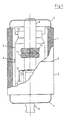
- the vacuum interrupter has an insulating ceramic jacket, consisting of two partial cylinders 1, 2, which are soldered to one another with the interposition of a metal ring 3.
- a condensation shield 5 formed from titanium, austenitic stainless steel or copper or their alloys is fixed concentrically to the cylinders 1, 2, which protect them against arcing products.
- the ceramic jacket is closed on both sides by metallic covers 6, 7 made of austenitic stainless steel or titanium.
- a fixed ladder stem 8 and a movable ladder stem 9 protrude through them on the one hand. Both stems carry contact pieces 10, 11 inside the switching chamber, which can be brought into contact with one another
- the protective shield 13 arranged prevents the switch-off arc from acting directly on the bellows 12.
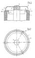
- Metallic control screens 14 each cover the inner end edge of the cylindrical ceramic jacket. They contain centering lugs with which the covers 6, 7 can be aligned concentrically with the partial cylinders 1, 2. On the one hand, such a centering approach is formed by tabs 15 issued from the control screens 14, which, overlapping the inner edge of the respective forehead of the partial cylinder 1, 2, center on the inside of the partial cylinder. On the other hand, the control screen 14 forms with the extension 16 extending on the end face of the partial cylinders 1, 2 an annular shoulder 17, over which the respective cover 1, 2 can be pushed centering.
- a so-called soldering group is put together and between the parts solder, e.g. B. introduced in the form of a ring foil.
- FIG. 2 there is such a fuselage 18, 19, 20 for connecting the parts 8, 6 and 6, 16 and finally 16, 1 in the form of ring foils.
- a sealing solder 21 in the form of solder blocks is arranged at three points on the circumference.
- economical use - especially because of the high price - is advisable.
- it contains palladium.
- a gap is formed between the individual solder blocks, through which the gases are pumped out of the interior of the chamber, in particular during degassing annealing.
- the sealing solder 21 accordingly has a higher melting temperature than the joining notes used.
- the following materials are connected to the silver-containing Fügelot: - copper / copper, - copper / stainless steel, - stainless steel / stainless steel, - ceramic / copper, - ceramics / ceramics as well - Titanium / ceramic.
- the control screen 14 including its extension 16 is made of copper; as a compensator, it absorbs the different elongations between the stainless steel cover 6 and the ceramic cylinder 1.
- the lid 6 abuts the extension 16.
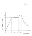
- FIG. 4 shows the soldering cycle with integrated degassing annealing of stainless steel or titanium in the form of a diagram.
- T E the degassing temperature of stainless steel or titanium
- T L the liquidus temperature of the highest melting solder, namely the sealing solder
- - t E annealing time of the degassing annealing process
- - t L holding time of the soldering temperature T L.
- the temperature of the annealing furnace is continuously raised to the degassing annealing temperature T E of stainless steel or titanium.
- T E the degassing annealing temperature
- the annealing temperature should be at least 860 ° C and for steel parts with material number 1.4550, however, at least 900 ° C.
- the surface oxide layer begins to dissolve and the joint marks 18, 19, 20 are usually already in the liquidus phase.
- the annealing time t E can be reduced to at least 10 minutes.
- the temperature is briefly increased to the melting temperature T L of the sealing solder 21.
- T L melting temperature
- the solder flows and the cover 6 settles onto the ceramic cylinder 1, closing the pumping gaps.
- all solders solidify and the vacuum interrupter is tightly closed.
Landscapes
- Chemical & Material Sciences (AREA)
- Engineering & Computer Science (AREA)
- Ceramic Engineering (AREA)
- Materials Engineering (AREA)
- Structural Engineering (AREA)
- Organic Chemistry (AREA)
- High-Tension Arc-Extinguishing Switches Without Spraying Means (AREA)
- Ceramic Products (AREA)
- Contacts (AREA)
Abstract
Description
- Die Erfindung betrifft ein Verfahren zur Herstellung einer Vakuumschaltkammer gemäß Oberbegriff des Anspruches 1.
- Ein solches Verfahren geht aus der DD-PS 13 46 93 als bekannt hervor. Beim bekannten Verfahren sollen in einem Ofenzyklus zunächst alle Einzelteile entgast werden, bis die Schmelztemperatur des Lotes mit niedriger Schmelztemperatur erreicht ist. In der Regel wird die Temperatur dabei kontinuierlich bis zur Schmelztemperatur des Lotes hochgefahren. Die hochreinen Kupferteile enthalten nur noch geringe Gasmengen, und die eingesetzten größeren Metallteile, wie Deckel, sind vor dem Einfügen in die Lötgruppe üblicherweise in einem speziellen Entgasungsverfahren vorbehandelt worden. Hierzu wird im Journal of Vacuum Science and Technology 1972, Vol. 9. NE 4, July-August 1972, Seite 1203 - 1208, by E. Fisher: "Two Kilometers of 10⁻¹⁰ Torr, the CERN Intersecting Storage Rings for Protons" berichtet, daß Entgasungszyklen von 950° C während ein bis zwei Stunden bei einem Druck von kleiner 10⁻⁵ Torr für 2 bis 2,5 mm dicke Edelstahlteile optimale Ergebnisse bezüglich Entgasung und Reinigung liefern.
- Dieses Entgasungsglühen erfordert einen separaten Ofenzyklus. Im übrigen sind die verwendeten silberhaltigen Fügelote sehr teuer, da sie Palladium enthalten.
- Die Aufgabe der Erfindung ist es, den Aufwand für die Herstellung der Vakuumschaltkammer zu vermindern.
- Dies gelingt mit den kennzeichnenden Merkmalen des Anspruches 1.
- Demzufolge wird in einem einzigen Ofenzyklus die Lötung der Lötgruppe sowie die Entgasung, insbesondere der Edelstahl- bzw. der Titanteile, vorgenommen. Eine Besonderheit besteht darin, daß während des Entgasens das erste niedrigschmelzende Lot sich in der Regel in der Liquidusphase befindet. Damit ist es möglich, trotz der relativ hohen Entgasungstemperatur von mindestens 860°C ein preiswertes, bei niedrigen Temperaturen schmelzendes Silberlot als Fügelot einzusetzen. Hierfür eignet sich besonders das Lot B-Ag 72 Cu780 mit 72 Gew. % Silber sowie 28 % Kupfer.
- Es wurde gefunden, daß ungeachtet der relativ langen Einwirkzeit des flüssigen Silberlotes keine Versprödungseffekte an der Edelstahllötfläche eintreten. Auch die mit dem Edelstahl bzw. dem Titan oder dessen Legierungen zu verbindenden Kupferteile neigen nicht zur Versprödung. Zwar diffundiert das Silber in das Kupfer ein, jedoch nur in feindisperser, d. h. unschädlicher Form. Insbesondere ist es mit dem Verfahren nach der Erfindung möglich, einen separaten Ofenzyklus für das Entgasungsglühen einzusparen. Neben dieser Kostenersparnis ergibt sich mit dem neuen Verfahren eine qualitative Verbesserung der Oberflächengüte bzw. -reinheit der Kammerteile, da diese nach der Entgasung nicht erneut kontaminiert werden können. Dadurch werden derart niedrige Totaldrükke der verschlossenen Kammer erreicht, daß der Einsatz eines Getters nicht mehr zwingend notwendig ist.
- Je geringer die Wandstärke der Edelstahl- bzw. Titanteile ausfällt, desto geringer kann die Glühdauer für deren Entgasung gewählt werden. Bei Wandstärken von 1 mm oder kleiner kann die Glühdauer auf minimal 10 Minuten reduziert werden.
- Das Erfindung wird anhand von schematischen Darstellungen beispielhaft erläutert.
- Es zeigen:
- Figur 1 einen Teillängsschnitt durch eine Vakuumschaltkammer;
- Figur 2 ein vergrößerter Teillängsschnitt im Bereich des Deckels mit feststehendem Leiterstengel;
- Figur 3 eine Draufsicht der Anordnung nach Figur 2;
- Figur 4 eine Darstellung eines Ofenzykluses hinsichtlich Temperatur und Zeit.
- Die Vakuumschaltkammer besitzt einen Isolierkeramikmantel, bestehend aus zwei Teilzylindern 1, 2, die unter Zwischenlage eines Metallringes 3 aufeinandergelötet sind. An einem Kragen 4 des Metallringes ist ein aus Titan, austenitischem Edelstahl oder Kupfer bzw. deren Legierungen, gebildeter Kondensationsschirm 5 konzentrisch zu den Zylindern 1, 2 - diese gegen Lichtbogenprodukte schützend - festgemacht.
- Der Keramikmantel ist beidseitig von metallischen Dekkeln 6, 7 aus nichtrostendem austenitischem Edelstahl oder Titan abgeschlossen. Durch diese ragt einerseits ein feststehender Leiterstengel 8 sowie andererseits ein beweglicher Leiterstengel 9. Beide Stengel tragen im Inneren der Schaltkammer miteinander in Kontakt bringbare Kontaktstücke 10, 11. Ein Metallbalg 12 besorgt die Abdichtung zwischen dem beweglichen Leiterstengel 9 und dem zugehörigen Deckel 7. Ein haubenartig angeordneter Schutzschirm 13 verhindert ein direktes Einwirken des Ausschaltlichtbogens auf den Balg 12.
- Metallische Steuerschirme 14 überdecken jeweils die innere stirnseitige Kante des zylindrischen Keramikmantels. Sie enthalten Zentrieransätze, mit denen die Dekkel 6, 7 konzentrisch zu den Teilzylindern 1, 2 ausrichtbar sind. Zum einen wird ein solcher Zentrieransatz von aus den Steuerschirmen 14 ausgestellten Laschen 15 gebildet, die sich, die innere Kante der jeweiligen Stirn des Teilzylinders 1, 2 übergreifend, an der Innenseite der Teilzylinder zentrierend anlegen. Andererseits bildet der Steuerschirm 14 mit dem auf der Stirnseite der Teilzylinder 1, 2 sich erstreckenden Fortsatz 16 eine Ringschulter 17, über die der jeweilige Deckel 1, 2 zentrierend geschoben werden kann. Für das Fügen (Verbinden) der lötfähigen Teile der Vakuumschaltkammer wird eine sog. Lötgruppe zusammengestellt und zwischen die Teile Lot, z. B. in Ringfolienform, eingebracht.
- Wie aus Figur 2 ersichtlich, ist ein solches Fügelot 18, 19, 20 zum Verbinden der Teile 8, 6 sowie 6, 16 und schließlich 16, 1 in Form von Ringfolien vorhanden. Zwischen den Fortsatz 16 des Steuerschirmes 14 sowie dem Lot 20 ist an drei Stellen auf dem Kreisumfang ein Verschlußlot 21 in Form von Lotklötzen angeordnet. Für dieses Lot ist eine sparsame Verwendung - insbesondere wegen des hohen Preises - angezeigt. In der Regel enthält es Palladium. Zwischen den einzelnen Lotklötzen entsteht ein Spalt, über den die Gase aus dem Kammerinneren, insbesondere beim Entgasungsglühen, abgepumpt werden. Das Verschlußlot 21 besitzt demnach eine höhere Schmelztemperatur als die eingesetzten Fügelote.
- In der Vakuumschaltkammer werden z. B. folgende Materialien mit dem silberhaltigen Fügelot verbunden:
- Kupfer/Kuper,
- Kupfer/Edelstahl,
- Edelstahl/Edelstahl,
- Keramik/Kupfer,
- Keramik/Keramik sowie
- Titan/Keramik. - Der Steuerschirm 14 einschließlich seines Fortsatzes 16 besteht aus Kupfer; er nimmt als Kompensator die unterschiedlichen Längendehnungen zwischen dem Edelstahldekkel 6 sowie dem Keramikzylinder 1 auf. Der Deckel 6 stößt stumpf auf den Fortsatz 16 auf.
- In Figur 4 ist der Lötzyklus mit integriertem Entgasungsglühen von Edelstahl bzw. Titan in Form eines Diagrammes dargestellt.
- Es bedeutet:
- TE = die Entgasungstemperatur von Edelstahl bzw. Titan,
- TL = die Liquidustemperatur des höchst schmelzenden Lotes, nämlich des Verschlußlotes,
- tE = Glühdauer des Entgasungsglühvorganges,
- tL = Haltezeit der Löttemperatur TL. - Zunächst wird die Temperatur des Glühofens kontinuierlich bis auf die Entgasungsglühtemperatur TE von Edelstahl bzw. Titan hochgefahren. Diese ist abhängig von der Werkstoffart, um z. B. ein sicheres Benetzen der Edelstahlteile zu gewährleisten. Bei Stählen z. B. gemäß Werkstoffnummer 1.4301 bzw. 1.4306 sollte die Glühtemperatur mindestens 860°C betragen und bei Stahlteilen mit der Werkstoffnummer 1.4550 hingegen mindestens 900°C. Bei diesen Temperaturen beginnt sich die Oberflächenoxidschicht aufzulösen und die Fügelote 18, 19, 20 befinden sich in der Regel schon in der Liquidusphase. Sind z. B. Edelstahl- bzw. Titanteile mit Wandstärken in der Größenordnung von 1 mm vorhanden, so kann die Glühdauer tE auf mindestens 10 Minuten herabgesetzt werden. Nach dem Entgasen wird die Temperatur kurz auf die Schmelztemperatur TL des Verschlußlotes 21 erhöht. Das Lot verfließt und der Deckel 6 setzt sich - die Auspumpspalte verschließend - auf den Keramikzylinder 1 ab. In der anschließenden Abkühlphase verfestigen sich alle Lote und die Vakuumschaltkammer ist dicht verschlossen.
Claims (5)
Applications Claiming Priority (4)
| Application Number | Priority Date | Filing Date | Title |
|---|---|---|---|
| DE3923528 | 1989-07-15 | ||
| DE3923528 | 1989-07-15 | ||
| DE3926619A DE3926619C2 (de) | 1989-07-15 | 1989-08-11 | Verfahren zur herstellung einer vakuumschaltkammer |
| DE3926619 | 1989-08-11 |
Publications (3)
| Publication Number | Publication Date |
|---|---|
| EP0409047A2 true EP0409047A2 (de) | 1991-01-23 |
| EP0409047A3 EP0409047A3 (en) | 1992-06-03 |
| EP0409047B1 EP0409047B1 (de) | 1994-09-21 |
Family
ID=25883094
Family Applications (1)
| Application Number | Title | Priority Date | Filing Date |
|---|---|---|---|
| EP90113141A Expired - Lifetime EP0409047B1 (de) | 1989-07-15 | 1990-07-10 | Verfahren zur Herstellung einer Vakuumschaltkammer |
Country Status (2)
| Country | Link |
|---|---|
| EP (1) | EP0409047B1 (de) |
| DE (2) | DE3926619C2 (de) |
Cited By (3)
| Publication number | Priority date | Publication date | Assignee | Title |
|---|---|---|---|---|
| EP0682351A1 (de) * | 1994-05-12 | 1995-11-15 | Kabushiki Kaisha Toshiba | Vakuumschalter und Verfahren zur Herstellung desselben |
| EP0780868A3 (de) * | 1995-12-21 | 1999-04-28 | Alstom Uk Ltd | Elektrisch leitender Schirm für einen Vakuumschalter |
| WO2010006830A1 (de) * | 2008-07-14 | 2010-01-21 | Siemens Aktiengesellschaft | Verfahren und vorrichtung zur herstellung von vakuumschaltröhren oder baugruppen von vakuumschaltröhren und vakuumschaltröhre |
Families Citing this family (4)
| Publication number | Priority date | Publication date | Assignee | Title |
|---|---|---|---|---|
| DE4106761A1 (de) * | 1991-03-04 | 1992-09-10 | Leybold Ag | Verfahren zur herstellung von ventilinnenteilen fuer vakuumventile mit ventilteller und faltenbalg sowie nach diesem verfahren hergestellte innenteile |
| DE9319945U1 (de) * | 1993-12-21 | 1995-04-20 | Siemens AG, 80333 München | Lötring für vakuumelektronische Bauelemente |
| JP3361932B2 (ja) * | 1996-05-29 | 2003-01-07 | 三菱電機株式会社 | 真空バルブ |
| JP4765538B2 (ja) * | 2005-10-20 | 2011-09-07 | 富士電機機器制御株式会社 | 真空バルブ、真空バルブの製造方法 |
Family Cites Families (9)
| Publication number | Priority date | Publication date | Assignee | Title |
|---|---|---|---|---|
| CH242550A (de) * | 1944-03-16 | 1946-05-31 | Patelhold Patentverwertung | Verfahren zur vakuumdichten Verbindung eines keramischen Körpers mit einem zweiten Körper. |
| GB1318651A (en) * | 1969-09-30 | 1973-05-31 | Westinghouse Electric Corp | Method of sealing and evacuating vacuum envelopes |
| GB1504666A (en) * | 1975-03-22 | 1978-03-22 | Gemvac Kk | Vacuum power interrupter and method of making the same |
| ZA767617B (en) * | 1976-01-19 | 1977-11-30 | Westinghouse Electric Corp | An improvement in or relating to low voltage vacuum shorting switch |
| DD134693A1 (de) * | 1977-12-19 | 1979-03-14 | Bahder Hans Peter | Verfahren zum evakuieren und verschliessen von elektrischen geraeten |
| DD135661A1 (de) * | 1978-02-01 | 1979-05-16 | Eckehard Gebauer | Vakuumschaltkammer |
| NL178680C (nl) * | 1979-03-05 | 1986-05-01 | Hazemeijer Bv | Werkwijze voor het tot stand brengen van een stompe hardsoldeerverbinding tussen metaal en keramisch materiaal. |
| DE3628174A1 (de) * | 1986-08-20 | 1988-02-25 | Calor Emag Elektrizitaets Ag | Vakuum-schaltkammer |
| DE8810941U1 (de) * | 1988-08-30 | 1988-10-13 | Calor-Emag Elektrizitäts-AG, 4030 Ratingen | Vakuum-Schaltkammer |
-
1989
- 1989-08-11 DE DE3926619A patent/DE3926619C2/de not_active Expired - Fee Related
-
1990
- 1990-07-10 DE DE59007205T patent/DE59007205D1/de not_active Expired - Fee Related
- 1990-07-10 EP EP90113141A patent/EP0409047B1/de not_active Expired - Lifetime
Cited By (6)
| Publication number | Priority date | Publication date | Assignee | Title |
|---|---|---|---|---|
| EP0682351A1 (de) * | 1994-05-12 | 1995-11-15 | Kabushiki Kaisha Toshiba | Vakuumschalter und Verfahren zur Herstellung desselben |
| US5687472A (en) * | 1994-05-12 | 1997-11-18 | Kabushiki Kaisha Toshiba | Method of manufacturing a vacuum interrupter |
| EP0780868A3 (de) * | 1995-12-21 | 1999-04-28 | Alstom Uk Ltd | Elektrisch leitender Schirm für einen Vakuumschalter |
| WO2010006830A1 (de) * | 2008-07-14 | 2010-01-21 | Siemens Aktiengesellschaft | Verfahren und vorrichtung zur herstellung von vakuumschaltröhren oder baugruppen von vakuumschaltröhren und vakuumschaltröhre |
| CN102089845A (zh) * | 2008-07-14 | 2011-06-08 | 西门子公司 | 制造真空开关管或真空开关管组件的方法和装置及真空开关管 |
| CN102089845B (zh) * | 2008-07-14 | 2013-12-18 | 西门子公司 | 制造真空开关管或真空开关管组件的方法和装置及真空开关管 |
Also Published As
| Publication number | Publication date |
|---|---|
| DE3926619A1 (de) | 1991-01-24 |
| DE3926619C2 (de) | 1993-11-04 |
| EP0409047A3 (en) | 1992-06-03 |
| EP0409047B1 (de) | 1994-09-21 |
| DE59007205D1 (de) | 1994-10-27 |
Similar Documents
| Publication | Publication Date | Title |
|---|---|---|
| DE3931774C2 (de) | ||
| DE2659871A1 (de) | Vakuumleistungsschalter und verfahren zu seiner herstellung | |
| DE102006041782B4 (de) | Vakuumröhre und Verfahren zur Herstellung einer Vakuumröhre | |
| EP0409047B1 (de) | Verfahren zur Herstellung einer Vakuumschaltkammer | |
| DE2308913A1 (de) | Vakuum-lichtbogenvorrichtung | |
| DE734115C (de) | Verfahren zur Herstellung grossflaechiger Verschmelzungen zwischen Glas und Metall | |
| EP0364430A1 (de) | Vormaterial für die Erzeugung von Verbundwerkstoffen | |
| DE102020124916B4 (de) | Befestigung eines optisch transparenten Fensters auf einem metallischen Werkstück | |
| DE2039063A1 (de) | Vakuumschalter | |
| DE2750002A1 (de) | Spannungsstosschutzvorrichtung | |
| EP0008068B1 (de) | Verbundwerkstoff und Verfahren zu dessen Herstellung | |
| DE69213662T2 (de) | Vakuumschalter | |
| DE2257258A1 (de) | Vakuum-schalterkontakte und verfahren zu ihrer herstellung | |
| DE3639983A1 (de) | Fuegeverfahren zur verbindung von normal- und supraleitenden materialien | |
| DE2044277C3 (de) | Verfahren zur Herstellung eines aus zwei Keramikröhren bestehenden evakuierten Gehäuses | |
| DE1640190A1 (de) | Schalteinrichtung mit steuerbarer Vakuum-Schaltfunkenstrecke | |
| DE889653C (de) | Vakuumdichte Stromeinfuehrunng durch Gefaesswaende aus Glas, insbesondere aus Quarzglas, oder aus keramischem Werkstoff und Verfahren zur Herstellung einer solchen Stromeinfuehrung | |
| DE1915198B2 (de) | Vakuumschalter | |
| DE767896C (de) | Hitzebestaendige Elektrodeneinfuehrung fuer Vakuumentladungsapparate, z. B. Quecksilberdampfgleichrichter, mit metallenem, von der Vakuum-pumpe abgetrenntem Vakuumgefaess | |
| DE1107748B (de) | Vakuumdichte Durchfuehrung mit einem Isolierkoerper aus einer bei hoher Temperatur schmelzbaren Masse, z. B. Glas, Emailmasse od. dgl. | |
| AT290262B (de) | Gehaeuse fuer bauelemente der elektrotechnik | |
| DE8709569U1 (de) | Vakuum-Schaltkammer | |
| DE1045887B (de) | Gasdichte Verbindung zwischen einem Metall und einem isolierenden Werkstoff und Verfahren zu ihrer Herstellung | |
| EP0379603B1 (de) | Verfahren zum stoffschlüssigen Verbinden von Werkstücken grosser Abmessungen aus siliciuminfiltriertem Siliciumcarbid durch elektrische Widerstandsheizung und Anordnung zur Durchführung des Verfahrens. | |
| AT256157B (de) | Verfahren zur Verbindung von Eisen oder Eisenlegierungen mit Gegenständen aus Kohlenstoff |
Legal Events
| Date | Code | Title | Description |
|---|---|---|---|
| PUAI | Public reference made under article 153(3) epc to a published international application that has entered the european phase |
Free format text: ORIGINAL CODE: 0009012 |
|
| AK | Designated contracting states |
Kind code of ref document: A2 Designated state(s): DE GB IT NL |
|
| PUAL | Search report despatched |
Free format text: ORIGINAL CODE: 0009013 |
|
| AK | Designated contracting states |
Kind code of ref document: A3 Designated state(s): DE GB IT NL |
|
| 17P | Request for examination filed |
Effective date: 19920623 |
|
| 17Q | First examination report despatched |
Effective date: 19940308 |
|
| GRAA | (expected) grant |
Free format text: ORIGINAL CODE: 0009210 |
|
| ITF | It: translation for a ep patent filed | ||
| AK | Designated contracting states |
Kind code of ref document: B1 Designated state(s): DE GB IT NL |
|
| REF | Corresponds to: |
Ref document number: 59007205 Country of ref document: DE Date of ref document: 19941027 |
|
| GBT | Gb: translation of ep patent filed (gb section 77(6)(a)/1977) |
Effective date: 19941007 |
|
| PGFP | Annual fee paid to national office [announced via postgrant information from national office to epo] |
Ref country code: GB Payment date: 19950626 Year of fee payment: 6 |
|
| PGFP | Annual fee paid to national office [announced via postgrant information from national office to epo] |
Ref country code: NL Payment date: 19950628 Year of fee payment: 6 |
|
| PLBE | No opposition filed within time limit |
Free format text: ORIGINAL CODE: 0009261 |
|
| STAA | Information on the status of an ep patent application or granted ep patent |
Free format text: STATUS: NO OPPOSITION FILED WITHIN TIME LIMIT |
|
| PGFP | Annual fee paid to national office [announced via postgrant information from national office to epo] |
Ref country code: DE Payment date: 19950818 Year of fee payment: 6 |
|
| 26N | No opposition filed | ||
| PG25 | Lapsed in a contracting state [announced via postgrant information from national office to epo] |
Ref country code: GB Effective date: 19960710 |
|
| PG25 | Lapsed in a contracting state [announced via postgrant information from national office to epo] |
Ref country code: NL Effective date: 19970201 |
|
| GBPC | Gb: european patent ceased through non-payment of renewal fee |
Effective date: 19960710 |
|
| NLV4 | Nl: lapsed or anulled due to non-payment of the annual fee |
Effective date: 19970201 |
|
| PG25 | Lapsed in a contracting state [announced via postgrant information from national office to epo] |
Ref country code: DE Effective date: 19970402 |
|
| PG25 | Lapsed in a contracting state [announced via postgrant information from national office to epo] |
Ref country code: IT Free format text: LAPSE BECAUSE OF NON-PAYMENT OF DUE FEES;WARNING: LAPSES OF ITALIAN PATENTS WITH EFFECTIVE DATE BEFORE 2007 MAY HAVE OCCURRED AT ANY TIME BEFORE 2007. THE CORRECT EFFECTIVE DATE MAY BE DIFFERENT FROM THE ONE RECORDED. Effective date: 20050710 |