EP0409039B1 - Bioreacteur - Google Patents
Bioreacteur Download PDFInfo
- Publication number
- EP0409039B1 EP0409039B1 EP90113095A EP90113095A EP0409039B1 EP 0409039 B1 EP0409039 B1 EP 0409039B1 EP 90113095 A EP90113095 A EP 90113095A EP 90113095 A EP90113095 A EP 90113095A EP 0409039 B1 EP0409039 B1 EP 0409039B1
- Authority
- EP
- European Patent Office
- Prior art keywords
- stirring
- bioreactor according
- stirring apparatus
- constructed
- reactor vessel
- Prior art date
- Legal status (The legal status is an assumption and is not a legal conclusion. Google has not performed a legal analysis and makes no representation as to the accuracy of the status listed.)
- Expired - Lifetime
Links
Images

Classifications
-
- C—CHEMISTRY; METALLURGY
- C12—BIOCHEMISTRY; BEER; SPIRITS; WINE; VINEGAR; MICROBIOLOGY; ENZYMOLOGY; MUTATION OR GENETIC ENGINEERING
- C12M—APPARATUS FOR ENZYMOLOGY OR MICROBIOLOGY; APPARATUS FOR CULTURING MICROORGANISMS FOR PRODUCING BIOMASS, FOR GROWING CELLS OR FOR OBTAINING FERMENTATION OR METABOLIC PRODUCTS, i.e. BIOREACTORS OR FERMENTERS
- C12M27/00—Means for mixing, agitating or circulating fluids in the vessel
- C12M27/02—Stirrer or mobile mixing elements
-
- B—PERFORMING OPERATIONS; TRANSPORTING
- B01—PHYSICAL OR CHEMICAL PROCESSES OR APPARATUS IN GENERAL
- B01F—MIXING, e.g. DISSOLVING, EMULSIFYING OR DISPERSING
- B01F31/00—Mixers with shaking, oscillating, or vibrating mechanisms
- B01F31/42—Mixers with shaking, oscillating, or vibrating mechanisms with pendulum stirrers, i.e. with stirrers suspended so as to oscillate about fixed points or axes
-
- C—CHEMISTRY; METALLURGY
- C12—BIOCHEMISTRY; BEER; SPIRITS; WINE; VINEGAR; MICROBIOLOGY; ENZYMOLOGY; MUTATION OR GENETIC ENGINEERING
- C12M—APPARATUS FOR ENZYMOLOGY OR MICROBIOLOGY; APPARATUS FOR CULTURING MICROORGANISMS FOR PRODUCING BIOMASS, FOR GROWING CELLS OR FOR OBTAINING FERMENTATION OR METABOLIC PRODUCTS, i.e. BIOREACTORS OR FERMENTERS
- C12M27/00—Means for mixing, agitating or circulating fluids in the vessel
- C12M27/18—Flow directing inserts
- C12M27/20—Baffles; Ribs; Ribbons; Auger vanes
Definitions
- the invention relates to a bioreactor with a reactor vessel with at least one opening, which is closed by at least one cover, with at least one stirring tool passed through the cover, in particular in the manner of a Venetian stirrer, the storage of which on the part of the bushing pointing outwards Stirring tool is arranged, the stirring tool being connected to a stirrer drive on its part facing outward with the leadthrough.
- a generic bioreactor is known from NL-A 8 203 579. Although this known bioreactor is suitable for gentle and uniform stirring of a substance, there is no suitable possibility of enriching the substance with a fluid.
- a tilting reactor is known from FR-A 1 604 693, in which air can be introduced via a stirring element. At the air outlet openings of the agitator, however, turbulence with strong shear stresses occurs due to the injection pressure, but this has a negative influence on biomass, in particular mammalian cells.
- the invention has for its object to provide a bioreactor of the generic type which allows a gentle and uniform fluid supply into a substance located in the bioreactor and which can also be used on an industrial scale.
- the stirring tool can be used in an advantageous manner for enrichment, in particular oxygen enrichment, of the mass located in the reactor vessel if the stirring tool has a cage with a fluid supply which is surrounded by a diffusion layer.
- the diffusion layer is preferably designed as a woven fabric, in particular as a noble metal woven fabric.
- the function of storing the stirring element and sealing the rector gate are divided.
- a thinner elastic seal can also be used in a large-scale implementation of a bioreactor, which meets the requirements for the elasticity of the seal when the stirring tool is deflected.
- the seal is not used to support the mixing tool.
- the storage of the stirring tool is preferably designed as a gimbal and arranged above the seal, whereby the storage can be easily maintained.
- the stirring tool is designed in the manner of a Venetian stirrer or a paddle, edges of the stirring tool being rounded in order to avoid introducing high shear forces into the substance to be stirred.
- the stirring tool can be designed, for example, as a stirring rod which has the profile of a C. The flow resistance then depends on the direction of movement of the stirring rod, since the flow resistance of the stirring rod is different on different sides.
- the stirring tool or the stirring rod can be moved in different ways. Circular or elliptical movements are expedient. On the other hand, wobble-like movements, which can be thought of as superimposing two circular movements, have proven to be very advantageous.
- the stirring tool can, for example, also be suspended in the manner of a pendulum at its upper end on a cross-head joint, the deflection of the stirring tool being able to take place by a thrust crank drive acting somewhat further down.
- the mounting for the stirring tool is arranged in the area of the bushing.
- the agitator drive can then have, for example, a cam gear mechanism which engages at the upper end of the agitator tool.
- the stirrer drive has a driven circular disk for generating a wobble movement of the stirring tool, to which a further, also rotatably driven second circular disk is fastened, in which a guide for the stirring tool is formed eccentrically.
- the wobble corresponds approximately to the manual stirring movement when stirring chemical or biological samples.
- This type of stirring movement is particularly advantageous for stirring biological substances with sensitive cell contours because the stirring effect is transferred to the substance evenly while avoiding high shear forces.
- baffles can be formed in the reactor vessel.
- the baffles are preferably in the form of edges which point from the inner wall of the reactor vessel to the center of the vessel.
- the direction of rotation of the stirring tool can also be periodically reversed, it being possible to take breaks between the changes in direction of rotation, in which the inertia of the liquid mass is used to produce turbulence on the stationary stirring tool.
- the stirring tool itself acts as a baffle.
- baffles may not be necessary, which means that a cheaper reactor vessel can be used.
- a reactor vessel without a baffle is also advantageous compared to reactor vessels with baffles in terms of maintenance and cleaning work.
- an elastic region of the cover is formed by two rubber-elastic seals arranged parallel to one another. These rubber-elastic seals are formed between the stirring tool and a fixed part of the cover, the space between the seals being filled with a sealing liquid which is at least under the same pressure, in particular under a slight excess pressure, relative to the interior of the reactor vessel. In the event of a seal failure, two additional seal locks remain effective.
- the pressure of the sealing liquid in the intermediate space can be monitored by a controller and adjusted via supply and discharge lines. Toxic vapors are generated, for example, during the anaerobic breakdown of biological material.
- the stirring tool has a stirring rod on which at least one paddle wheel arrangement in the manner of a wind measuring wheel is rotatably mounted.
- the paddle wheel arrangement is also deflected, thereby achieving a stirring effect.
- the blades of the impeller are designed as transversely bisected circular ellipsoids, the cutting surface of which is concavely curved. The blades then have a very different flow resistance in both axial directions of the circular ellipsoid, which increases the stirring movement of the blade wheel arrangement.
- a plurality of paddle-like stirring bars arranged approximately parallel to the paddle-like arrangement on propeller-like suspensions can also be rotatably mounted on the stirring rod.
- These stirring bars preferably have a profile that corresponds to that of the transversely bisected circular ellipsoid. In this way, a large and uniform stirring effect is achieved. If the stirring bars to the bottom of the reactor vessel light Taper conically to the stir bar, the strips are in their position facing the wall of the reactor vessel approximately parallel to the wall of the reactor vessel. The distance between them can then be kept as small as possible, so that a good stirring of the entire volume of the reactor vessel is achieved.
- the agitators must have a large difference in flow resistance between the forward and backward movement and a high side resistance. In this way, the non-rotatably mounted arrangement is set into a rapid rotary movement, with the large lateral surface achieving a strong swirl during the lateral movement.
- the speed and the eccentricity of the tumbler can be changed as operating parameters.
- the stirring tool can be set into a stirring movement by an eccentric drive.
- the stirring tool is set into a stirring movement by a drive with a planetary gear.
- the drive shaft of a motor carries a sun gear of the planetary gear, while a gimbal for the upper part of the stirring tool is arranged on the cage for the planet gears.
- the planet gears are mounted between the sun gear and an internally toothed ring. If these planet gears are the same size, the planet gears are set in a slower rotation when the sun gear rotates, which is transferred to the cage and thus via the cardanic bearing to the stirring tool.
- Such a drive is therefore very suitable as a drive for the large-scale implementation of a bioreactor.
- the stirring tool carries at least one foam destroyer which has a multiplicity of walls which are formed parallel to the axis of the stirring tool.
- foam destroyer on the one hand allows thorough mixing of the mass in the reactor vessel and, on the other hand, prevents the formation of a troublesome foam crown.
- foam crowns have a very disruptive effect with regard to constant working conditions.
- a uniform and distributed over a large volume of the mass located in the reactor vessel is achieved if several stirring tools are arranged on different sides of the reactor vessel.
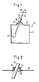
- the bioreactor 10 shown in FIG. 1 has a circular cylindrical reactor vessel 12, the open top of which is closed by a cover 14.
- the cover 14 has a central recess through which a stirring tool 16 designed as a stirring rod is guided into the reactor space inside the reactor vessel 12.
- the stirring rod 16 is paddle-shaped at its lower end 18 broadened.
- the stirring rod 16 is mounted on a cardanic suspension 20 above the passage of the stirring rod 16 through the cover 14.
- the upper end 24 of the stirring rod 16 is deflected parallel to the plane of the cover 14 by a drive 26 which is only indicated schematically. In this way, the stirring rod 16 can be pivoted in any manner.
- circular or elliptical orbits are conceivable.
- the stirring rod 16 is preferably moved in a tumbling manner. The wobble movement can be thought of as two superimposed acentric circular movements.
- FIG. 2 shows the area where a stirring rod 30 is passed through a cover 32 similar to the example described in FIG. 1.
- the stirring rod 30 and the cover 32 are connected to one another by two rubber-elastic seals 34, 36 arranged essentially parallel to one another.
- the space 38 between the two seals 34 and 36 is filled with a barrier liquid which is under a slight positive pressure relative to the reactor space. In this way, a secure sealing effect is maintained even if a seal is damaged. It is important to ensure that the barrier liquid is not toxic to the substance in the reactor chamber.
- the pressure of the sealing liquid can be constantly monitored via sensors, not shown, and regulated via supply and discharge lines, not shown.
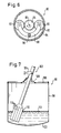
- FIG. 3 shows a stirring tool 40 which, in principle, can be used instead of the stirring rod 16 in the bioreactor 10 from FIG. 1.
- the stirring tool 40 consists of a stirring rod 42, at the lower end of which a paddle wheel arrangement 44 in the manner of a wind measuring wheel is rotatably mounted.
- the paddle wheel arrangement 44 shows the top view of the paddle wheel arrangement 44 in the axial direction of the stirring rod 42.
- the paddle wheel arrangement 44 consists of a propeller-like connecting strut 46 which is rotatably mounted in the middle on the stirring rod 42.
- a transversely bisected circular ellipsoid 48, 50 is arranged at each of the two outer ends of the propeller-like connecting strut 46, the cutting surface 52, 54 of the circular ellipsoids being concavely curved.
- FIG. 5 shows a bioreactor 60, the stirring tool 62 of which consists of a stirring rod 64 with three paddle wheel arrangements 66, 68, 70.
- the length of the connecting struts of the three vane wheel assemblies 66, 68, 70 decreases from the upper vane wheel assembly 66 to the lower vane wheel assembly 70.
- the spacing of the cross-sectioned circular ellipsoids 74, 76, 78 in all three paddle wheel arrangements 66, 68, 70 is essentially the same in their position facing the reactor wall 72.
- the three cross-sectioned ellipsoids 74, 76, 78 thus lie on a conical conical surface tapering to the lower end of the stirring rod 64, the walls of which are indicated by dashed lines.
- the rotatably mounted paddle wheel arrangements 66, 68, 70 can each have two, three or more stirring elements in the form of the cross-sectioned circular ellipsoids.
- FIG. 6 shows the partially sectioned top view of a planetary gear 80 for driving a stirring tool.
- the planetary gear 80 consists of an annular outer wall 82 with an internal toothing 84, two planet gears 90, 92 connected by a cage 88 and a sun gear 94 arranged between them, which is fixed on the shaft 95 of a motor.
- the two planet gears 90 and 92 have the same diameter and the same number of teeth.
- a ball joint guide 86 for the upper part of the stirring tool is formed on the cage 88 for connecting the two planet gears.
- the drive 80 is arranged above the reactor vessel, so that when the shaft 95 rotates, the ball joint guide 86 executes a circular movement for the stirring tool.
- the pivoting upper part of the stirring tool can be connected to the rotating cage 88 of the planetary gear by the ball joint guide 86.
- This drive 80 allows very large forces to be transmitted to the stirring tool over a long period of time.
- FIG. 7 shows a further bioreactor 96 with a circular cylindrical reactor vessel 98, the bottom 100 of which is convexly curved downward, so that the lower end of a stirring tool has an essentially equal distance from the bottom of the reactor vessel over the entire swivel range.
- the bioreactor 96 has a stirring tool 102, which is deflected at its upper end in a manner not shown by a drive.
- the stirring tool 102 is mounted on a gimbal 104.
- a rubber sleeve 108 in the manner of a corrugated tube compensator is provided between a cover 106 of the reactor vessel and the stirring tool 102 for sealing.
- the stirring tool 102 has a foam destroyer 110 at its lower end, which has a plurality of concentric circular-cylindrical tubes or tubes (not shown) that taper concentrically upwards.
- the foam condenses on the walls 112 of these tubes and drips when the in particular a circular movement of the foam destroyer 110 back into the liquid 114 located in the reactor vessel 98.
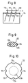
- FIG. 8 shows a bioreactor 114 with three stirring tools 116 arranged in series in a highly schematic manner.
- the stirring tools are mounted on suspension points 118. At their upper end, the stirring tools are connected by a push and pull rod 120 to a drive, not shown.
- the stirring tools 116 are deflected synchronously in this way.
- FIG. 9 shows the cross section of a stir bar 122.
- this stirring tool 122 which is designed in the manner of a paddle-shaped stirring rod, fluids, especially oxygen, can be introduced into the substance or liquid to be stirred.
- the stir bar consists of a cage 124, which is surrounded by a very fine-meshed stainless steel mesh 126.
- This type of oxygen supply can be referred to as indirect oxygen input into an organic substance to be stirred, this type of oxygen input being provided for very sensitive cells, such as mammalian cells.
- the fluid or oxygen is fed to the cage via a feed 128.
- the oxygen bubbles coagulate on the stainless steel mesh surface 126 and do not pass through it.
- the oxygen is dissolved in the liquid by diffusion and / or liquid transport through the mesh of the tissue 126 in the reactor space filled with growing cells.
- the diffusion or the liquid transport is accelerated by the movement of the stirring tool in the direction of diffusion.
- the stirring action of the stirring tool 122 prevents differences in the concentration of oxygen in the liquid in the reactor space.
- a wobbling movement while stirring achieves both a good stirring effect and a rapid diffusion of the oxygen into the liquid.
- an entire set of such stirring tools can be actuated, for example in the manner described in FIG. 8.
- Such cages can also be designed as a paddle wheel arrangement according to FIGS. 3 to 5 be, then it must be ensured that an oxygen supply is made possible at the transition points from the stirring rod to the paddle wheel arrangements.
- Such cages can also be circular cylindrical.
- FIG. 10 shows the cross section of a bioreactor 130.
- the circular-cylindrical reactor vessel 132 has four strips 134 protruding into the interior of the reactor, which serve as baffles, offset by 90 ° in the circumferential direction. In this way, sufficient swirling of the mass located in the reactor vessel 132 is effected even with a circular stirring movement of a stirring tool 136.
- stirring tools e.g. ten pieces to move synchronously. It is also possible to use stirring tools from several different sides, e.g. also from the side walls, into the reactor vessel, which then results in a more uniform stirring of the liquid in the reactor vessel, since to achieve the same stirring effect the deflection of each individual stirring tool can be less than if only a single stirring tool is used.
- the above-mentioned embodiments achieve a very gentle stirring action compared to propeller or magnetic bar stirrers, since the shear forces introduced into the mass to be mixed are not as great as in the known stirring techniques.
- the stirring techniques described can be implemented particularly in systems for large-scale or industrial needs.
Landscapes
- Chemical & Material Sciences (AREA)
- Organic Chemistry (AREA)
- Wood Science & Technology (AREA)
- Zoology (AREA)
- Life Sciences & Earth Sciences (AREA)
- Health & Medical Sciences (AREA)
- Engineering & Computer Science (AREA)
- Bioinformatics & Cheminformatics (AREA)
- Genetics & Genomics (AREA)
- Sustainable Development (AREA)
- General Engineering & Computer Science (AREA)
- Biochemistry (AREA)
- General Health & Medical Sciences (AREA)
- Microbiology (AREA)
- Biotechnology (AREA)
- Biomedical Technology (AREA)
- Chemical Kinetics & Catalysis (AREA)
- Apparatus Associated With Microorganisms And Enzymes (AREA)
- Mixers Of The Rotary Stirring Type (AREA)
- Mixers With Rotating Receptacles And Mixers With Vibration Mechanisms (AREA)
Claims (25)
- Bioréacteur comportant une cuve de réacteur avec au moins une ouverture qui est fermée par au moins un couvercle (14), au moins un dispositif agitateur (16, 122) qui traverse le couvercle (14), notamment un dispositif agitateur du type vénitien dont le palier (20) est disposé sur la partie du dispositif agitateur (16, 122) qui est tournée vers l'extérieur par rapport au passage, le dispositif agitateur (16, 122) au niveau de sa partie (24) tournée vers l'extérieur par rapport au passage étant lié à un mécanisme d'entraînement (26), caractérisé par le fait que le dispositif agitateur (122) comporte une cage (124) qui est entourée d'une couche de diffusion (126) et présente une arrivée de fluide (128).
- Bioréacteur selon la revendication 1, caractérisé par le fait que la couche de diffusion (126) est agencée sous forme de tissus, en particulier sous forme de tissus de métal précieux.
- Bioréacteur selon la revendication 1 ou 2, caractérisé par le fait que toutes les parties du dispositif agitateur sont constituées par des profilés creux qui communiquent entre eux et par le fait que des systèmes d'agitation de type augets, palettes ou tiges du dispositif agitateur sont agencés sous la forme de cages adaptées en tissu de métal précieux des fluides pouvant être envoyés aux cages à travers la partie du dispositif agitateur amenée à l'extérieur par l'intermédiaire du passage aux fins de répartition homogène dans la cuve de réacteur.
- Bioréacteur selon l'une des revendications 1 à 3, caractérisé par le fait que le fluide contient de l'oxygène.
- Bioréacteur selon la revendication 1, caractérisé par le fait que le mécanisme d'entraînement de l'agitateur comporte un mécanisme à came.
- Bioréacteur selon la revendication 1, caractérisé par le fait qu'afin de générer un mouvement de nutation du dispositif agitateur, le mécanisme d'entraînement comporte un plateau circulaire entraîné sur lequel est fixé de manière excentrée un deuxième plateau circulaire également entraîné en rotation dans lequel est aménagée une glissière excentrée pour le dispositif agitateur.
- Bioréacteur selon l'une des revendications précédentes, caractérisé par le fait que le palier pour le dispositif agitateur est disposé dans la région du passage.
- Bioréacteur selon l'une des revendications précédentes, caractérisé par le fait que des brise-lames (134) sont disposés à l'intérieur de la cuve de réacteur (132).
- Bioréacteur selon la revendication 8, caractérisé par le fait que les brise-lames (134) sont agencés sous la forme de bords qui s'étendent depuis la paroi intérieure de la cuve de réacteur (132) en direction de l'intérieur de celle-ci.
- Bioréacteur selon l'une des revendications précédentes, caractérisé par le fait que le dispositif agitateur est supporté au niveau de son extrémité supérieure et est entraîné plus loin vers le bas par un mécanisme à manivelle.
- Bioréacteur selon l'une des revendications précédentes, caractérisé par le fait qu'une zone élastique du couvercle (32) est constituée par deux joints (34, 36) qui présentent l'élasticité du caoutchouc et sont disposés parallèlement l'un à l'autre.
- Bioréacteur selon la revendication 11, caractérisé par le fait que les joints (34, 36) présentant l'élasticité du caoutchouc sont disposés entre le dispositif agitateur (30) et un partie fixe du couvercle (32) et par le fait que l'espace (38) entre les joints (34, 36) est rempli d'un liquide de barrage qui, par rapport à la chambre intérieure de la cuve de réacteur, est au moins à la même pression, notamment est à une pression légèrement supérieure.
- Bioréacteur selon l'une des revendications précédentes, caractérisé par le fait que le dispositif agitateur est agencé sous forme de tige d'agitateur à palette (18).
- Bioréacteur selon la revendication 13, caractérisé par le fait que la tige d' agitateur présente une section transversale asymétrique.
- Bioréacteur selon l'une des revendications 1 à 12, caractérisé par le fait que le dispositif agitateur (40) comporte une tige d'agitateur (42) sur laquelle est fixé au moins un ensemble de roue à augets (44) semblable à une roue d'anémomètre.
- Bioréacteur selon la revendication 15, caractérisé par le fait que les augets (48, 50) de la roue à augets ont la forme d'une ellipsoïde de révolution coupée en deux dans la direction transversale, dont la surface (52, 54) est concave.
- Bioréacteur selon l'une des revendications 1 à 12, caractérisé par le fait que le dispositif agitateur comporte au moins une tige d'agitateur sur laquelle plusieurs barrettes d'agitateur en forme de palettes disposées sensiblement parallèlement à la tige sont fixées sur des supports en forme d'hélice.
- Bioréacteur selon la revendication 17, caractérisé par le fait que les barrettes d'agitateur en direction du fond de la cuve de réacteur se rapprochent de la tige en formant un cône à faible pente.
- Bioréacteur selon l'une des revendication précédentes, caractérisé par le fait que le mécanisme d'entraînement du dispositif agitateur est constitué par un engrenage planétaire (80).
- Bioréacteur selon la revendication 19, caractérisé par le fait qu'un moyen de guidage à rotule (86) pour le dispositif agitateur est aménagé sur un carter (88) pour les roues planétaires (90, 92) de léngrenage planétaire.
- Bioréacteur selon l'une des revendications précédentes, caractérisé par le fait que le dispositif agitateur (102) porte au moins un dispositif (110) de destruction de la mousse qui présente une pluralité de parois (112) disposées parallèlement à l'axe du dispositif agitateur (102).
- Bioréacteur selon la revendication 21, caractérisé par le fait que les parois (112) sont agencées sous la forme de cylindre concentriques.
- Bioréacteur selon l'une des revendications précédentes, caractérisé par le fait que plusieurs dispositifs agitateurs sont disposés sur différentes faces de la cuve de réacteur.
- Bioréacteur selon la revendication 1, caractérisé par le fait que le support pour le dispositif agitateur est constitué par le mécanisme d'entraînement.
- Bioréacteur selon la revendication 24, caractérisé par le fait que le dispositif agitateur peut être entraîné en un mouvement de translation par le mécanisme d'entraînement.
Applications Claiming Priority (2)
| Application Number | Priority Date | Filing Date | Title |
|---|---|---|---|
| DE3923928A DE3923928A1 (de) | 1989-07-19 | 1989-07-19 | Bioreaktor |
| DE3923928 | 1989-07-19 |
Publications (2)
| Publication Number | Publication Date |
|---|---|
| EP0409039A1 EP0409039A1 (fr) | 1991-01-23 |
| EP0409039B1 true EP0409039B1 (fr) | 1994-11-02 |
Family
ID=6385401
Family Applications (1)
| Application Number | Title | Priority Date | Filing Date |
|---|---|---|---|
| EP90113095A Expired - Lifetime EP0409039B1 (fr) | 1989-07-19 | 1990-07-09 | Bioreacteur |
Country Status (5)
| Country | Link |
|---|---|
| EP (1) | EP0409039B1 (fr) |
| JP (1) | JPH0365175A (fr) |
| DE (2) | DE3923928A1 (fr) |
| DK (1) | DK0409039T3 (fr) |
| ES (1) | ES2065441T3 (fr) |
Families Citing this family (17)
| Publication number | Priority date | Publication date | Assignee | Title |
|---|---|---|---|---|
| US6086240A (en) * | 1999-07-16 | 2000-07-11 | Sierra Housewares, Inc. | Stirring Pitcher having pivotable stirring handle |
| MXPA03010551A (es) * | 2001-05-18 | 2004-07-01 | Chemineer | Instalacion de mezclado para tanques. |
| DE102005020460B4 (de) | 2005-04-29 | 2007-03-29 | Ika - Werke Gmbh & Co. Kg | Rühr- oder Dispergiervorrichtung |
| DE102005040511A1 (de) * | 2005-08-26 | 2007-03-01 | BSH Bosch und Siemens Hausgeräte GmbH | Küchengerät mit einer mittels einer Membran abgedichteten Werkzeugkupplung |
| DE102006022914B4 (de) * | 2006-05-15 | 2013-07-18 | Sartorius Stedim Biotech Gmbh | Bioreaktor |
| DE102007049077A1 (de) | 2007-10-12 | 2009-04-16 | IVET Ingenieurgesellschaft für Verfahrensentwicklung und Entsorgungstechnik mbH | Vorrichtung und Verfahren zum Gaseintrag in Flüssigkeiten. |
| CN101844048B (zh) * | 2010-03-08 | 2013-06-12 | 曾沂水 | 静密封搅拌器 |
| DE102010047305A1 (de) * | 2010-10-01 | 2012-04-05 | Ika-Werke Gmbh & Co. Kg | Misch-, Rühr- oder Dispergierverfahren und Vorrichtung hierfür |
| JP5931597B2 (ja) * | 2011-09-29 | 2016-06-08 | 株式会社神鋼環境ソリューション | 撹拌装置 |
| JP5789224B2 (ja) * | 2012-06-20 | 2015-10-07 | 株式会社神鋼環境ソリューション | 撹拌装置のシール材 |
| CN104046562B (zh) * | 2014-06-11 | 2016-05-25 | 苏州市金翔钛设备有限公司 | 一种搅拌反应器 |
| CN107213865A (zh) * | 2017-07-28 | 2017-09-29 | 洛阳市三诺化工有限公司 | 一种供生产p204磷酸酯萃取剂的反应罐使用的摆锤 |
| CN111097323A (zh) * | 2019-12-07 | 2020-05-05 | 天长市联嘉磁电科技有限公司 | 一种软磁铁氧体磁芯生产用制浆装置 |
| CN112429685A (zh) * | 2020-11-24 | 2021-03-02 | 安徽椒之骄农业科技有限公司 | 一种用于辣椒酱腌制窖藏坛封口材料及其制备方法 |
| CN113522132B (zh) * | 2021-07-19 | 2023-05-26 | 山东农业工程学院 | 一种农业滴灌用水肥药均混装置 |
| CN114392663A (zh) * | 2021-12-09 | 2022-04-26 | 华能伊春热电有限公司 | 一种螺旋匀料防堵装置 |
| CN116272550B (zh) * | 2023-04-10 | 2023-09-05 | 连云港师范高等专科学校 | 一种镧基超级电容器电极材料合成装置 |
Family Cites Families (15)
| Publication number | Priority date | Publication date | Assignee | Title |
|---|---|---|---|---|
| DE7435369U (de) * | 1975-02-13 | Heraeus W Gmbh | Rührvorrichtung | |
| CH295385A (de) * | 1948-05-14 | 1953-12-31 | Mueller Hans Dr Ing Chem | Vorrichtung zum Bewegen einer Flüssigkeit mittels eines vibrierenden Organs. |
| DE954926C (de) * | 1954-10-22 | 1956-12-27 | Erwin Stelzer | Milchruehrer |
| CH351948A (de) * | 1957-06-17 | 1961-02-15 | Ciba Geigy | Rühreinrichtung |
| FR1604693A (en) * | 1968-12-31 | 1972-01-03 | Vat for the culture of the aphthous virus - and for biological substances | |
| DE2061882A1 (en) * | 1970-12-16 | 1972-06-22 | Hoesch & Soehne Eberhard | Multi-stream stirrer assembly - with variable angle of incidence blades |
| GB1464733A (en) * | 1973-08-29 | 1977-02-16 | Terlet Nv Maschf | Mixing device |
| BE833947A (fr) * | 1974-10-23 | 1976-01-16 | Agitateur | |
| US3998435A (en) * | 1975-01-29 | 1976-12-21 | Bruyne Norman Adrian De | Oscillating stirrers |
| DE2625208C3 (de) * | 1976-06-04 | 1980-02-21 | Behringwerke Ag, 3550 Marburg | Fermenter |
| US4204774A (en) * | 1979-02-26 | 1980-05-27 | Bruyne Norman A De | Synchronous stirrer |
| NL8203579A (nl) * | 1982-09-15 | 1984-04-02 | Centraal Diergeneeskundig Inst | Mengvat. |
| DE3438657A1 (de) * | 1984-10-22 | 1986-04-24 | EKATO Industrieanlagen Verwaltungsgesellschaft mbH u. Co, 7860 Schopfheim | Turbine zum zerstoeren von schaum |
| DE3736316A1 (de) * | 1987-10-27 | 1989-05-11 | Loedige Maschbau Gmbh Geb | Reaktor zum behandeln von schuettguetern oder dergleichen |
| DE3739650C1 (de) * | 1987-11-23 | 1989-05-24 | Immuno Ag | Fermenter zum Zuechten von Zellkulturen |
-
1989
- 1989-07-19 DE DE3923928A patent/DE3923928A1/de active Granted
-
1990
- 1990-07-09 EP EP90113095A patent/EP0409039B1/fr not_active Expired - Lifetime
- 1990-07-09 DE DE59007608T patent/DE59007608D1/de not_active Expired - Fee Related
- 1990-07-09 ES ES90113095T patent/ES2065441T3/es not_active Expired - Lifetime
- 1990-07-09 DK DK90113095.5T patent/DK0409039T3/da active
- 1990-07-18 JP JP2191836A patent/JPH0365175A/ja active Pending
Also Published As
| Publication number | Publication date |
|---|---|
| ES2065441T3 (es) | 1995-02-16 |
| DE59007608D1 (de) | 1994-12-08 |
| DE3923928A1 (de) | 1991-01-24 |
| DE3923928C2 (fr) | 1991-06-13 |
| EP0409039A1 (fr) | 1991-01-23 |
| JPH0365175A (ja) | 1991-03-20 |
| DK0409039T3 (da) | 1995-04-24 |
Similar Documents
| Publication | Publication Date | Title |
|---|---|---|
| EP0409039B1 (fr) | Bioreacteur | |
| DE4110908C2 (de) | Vorrichtung zum Aufrechterhalten einer kontinuierlichen Mischung in einer Flüssigkeit, die Feststoffe und Gas enthält und zum gleichzeitigen Abtrennen von Gas oder von Gas und Feststoffen von der Flüssigkeit | |
| DE60107104T2 (de) | Verfahren und vorrichtung zur behandlung einer flüssigkeits-charge | |
| EP0063171B1 (fr) | Dispositif mélangeur | |
| DE69202775T2 (de) | Anlage zum Mischen zweier fluider Phasen durch mechanisches Rühren, insbesondere für die Wasserbehandlung durch Übertragung von oxydierendem Gas und Verwendung einer solchen Anlage. | |
| DE69328038T2 (de) | Verfahren und vorrichtung zum lagern und handhaben von abwasserschlämmen | |
| DE69810067T2 (de) | Vorrichtung und Verfahren zur Flüssigkeitsejektion | |
| DE4110907C2 (de) | Vorrichtung zum Aufrechterhalten einer kontinuierlichen Mischung in einer Flüssigkeit und zum gleichzeitigen Abtrennen einer anderen Flüssigkeit und eines Feststoffes aus der Flüssigkeit | |
| EP1055450A2 (fr) | Agitateur | |
| DE3901894A1 (de) | Vorrichtung zum mischen von stroemungsfaehigen, insbesondere pastoesen medien sowie verfahren zu deren betrieb | |
| DE69005365T2 (de) | Apparat zum Mischen von Viskosematerialien. | |
| DE69521114T2 (de) | Bioreaktor | |
| DE1557115B2 (de) | Vorrichtung zum mischen von fluessigkeiten | |
| EP0006597B1 (fr) | Procédé et dispositif pour l'aération d'eau | |
| DE2428615A1 (de) | Mischer | |
| EP0026023A1 (fr) | Dispositif de démoussage mécanique pour des réacteurs gaz/liquide | |
| DE69820122T2 (de) | Apparat zur suspension von kultivierten zellen aus gewebe und mikroorganismen | |
| DE19514931C2 (de) | Bio-Reaktor | |
| DE3520040A1 (de) | Vorrichtung zum mischen von gut | |
| DE102016114735A1 (de) | Rührwerkzeug | |
| DE1557230A1 (de) | Ruehrteil fuer einen Magnetruehrer | |
| DE69327596T2 (de) | Organisches abbausystem | |
| EP0342584B1 (fr) | Dispositif pour agiter des milieux de type liquide, pâteux et/ou granuleux | |
| DE1199736B (de) | Tellermischer | |
| DE3112994C2 (de) | Autoklav zum Aufbereiten von Kakaomasse |
Legal Events
| Date | Code | Title | Description |
|---|---|---|---|
| PUAI | Public reference made under article 153(3) epc to a published international application that has entered the european phase |
Free format text: ORIGINAL CODE: 0009012 |
|
| AK | Designated contracting states |
Kind code of ref document: A1 Designated state(s): CH DE DK ES FR GB LI NL |
|
| 17P | Request for examination filed |
Effective date: 19910627 |
|
| 17Q | First examination report despatched |
Effective date: 19930813 |
|
| GRAA | (expected) grant |
Free format text: ORIGINAL CODE: 0009210 |
|
| AK | Designated contracting states |
Kind code of ref document: B1 Designated state(s): CH DE DK ES FR GB LI NL |
|
| ET | Fr: translation filed | ||
| REF | Corresponds to: |
Ref document number: 59007608 Country of ref document: DE Date of ref document: 19941208 |
|
| GBT | Gb: translation of ep patent filed (gb section 77(6)(a)/1977) |
Effective date: 19941115 |
|
| REG | Reference to a national code |
Ref country code: ES Ref legal event code: FG2A Ref document number: 2065441 Country of ref document: ES Kind code of ref document: T3 |
|
| REG | Reference to a national code |
Ref country code: DK Ref legal event code: T3 |
|
| PLBE | No opposition filed within time limit |
Free format text: ORIGINAL CODE: 0009261 |
|
| STAA | Information on the status of an ep patent application or granted ep patent |
Free format text: STATUS: NO OPPOSITION FILED WITHIN TIME LIMIT |
|
| NLR4 | Nl: receipt of corrected translation in the netherlands language at the initiative of the proprietor of the patent | ||
| 26N | No opposition filed | ||
| PGFP | Annual fee paid to national office [announced via postgrant information from national office to epo] |
Ref country code: GB Payment date: 19970630 Year of fee payment: 8 |
|
| PGFP | Annual fee paid to national office [announced via postgrant information from national office to epo] |
Ref country code: ES Payment date: 19970714 Year of fee payment: 8 |
|
| PGFP | Annual fee paid to national office [announced via postgrant information from national office to epo] |
Ref country code: FR Payment date: 19970718 Year of fee payment: 8 |
|
| PGFP | Annual fee paid to national office [announced via postgrant information from national office to epo] |
Ref country code: CH Payment date: 19970721 Year of fee payment: 8 |
|
| PGFP | Annual fee paid to national office [announced via postgrant information from national office to epo] |
Ref country code: DK Payment date: 19970724 Year of fee payment: 8 |
|
| PGFP | Annual fee paid to national office [announced via postgrant information from national office to epo] |
Ref country code: NL Payment date: 19970731 Year of fee payment: 8 Ref country code: DE Payment date: 19970731 Year of fee payment: 8 |
|
| PG25 | Lapsed in a contracting state [announced via postgrant information from national office to epo] |
Ref country code: GB Free format text: LAPSE BECAUSE OF NON-PAYMENT OF DUE FEES Effective date: 19980709 |
|
| PG25 | Lapsed in a contracting state [announced via postgrant information from national office to epo] |
Ref country code: ES Free format text: LAPSE BECAUSE OF NON-PAYMENT OF DUE FEES Effective date: 19980710 |
|
| PG25 | Lapsed in a contracting state [announced via postgrant information from national office to epo] |
Ref country code: LI Free format text: LAPSE BECAUSE OF NON-PAYMENT OF DUE FEES Effective date: 19980731 Ref country code: DK Free format text: LAPSE BECAUSE OF NON-PAYMENT OF DUE FEES Effective date: 19980731 Ref country code: CH Free format text: LAPSE BECAUSE OF NON-PAYMENT OF DUE FEES Effective date: 19980731 |
|
| PG25 | Lapsed in a contracting state [announced via postgrant information from national office to epo] |
Ref country code: NL Free format text: LAPSE BECAUSE OF NON-PAYMENT OF DUE FEES Effective date: 19990201 |
|
| GBPC | Gb: european patent ceased through non-payment of renewal fee |
Effective date: 19980709 |
|
| REG | Reference to a national code |
Ref country code: CH Ref legal event code: PL |
|
| PG25 | Lapsed in a contracting state [announced via postgrant information from national office to epo] |
Ref country code: FR Free format text: LAPSE BECAUSE OF NON-PAYMENT OF DUE FEES Effective date: 19990331 |
|
| NLV4 | Nl: lapsed or anulled due to non-payment of the annual fee |
Effective date: 19990201 |
|
| PG25 | Lapsed in a contracting state [announced via postgrant information from national office to epo] |
Ref country code: DE Free format text: LAPSE BECAUSE OF NON-PAYMENT OF DUE FEES Effective date: 19990501 |
|
| REG | Reference to a national code |
Ref country code: FR Ref legal event code: ST |
|
| REG | Reference to a national code |
Ref country code: DK Ref legal event code: EBP |
|
| REG | Reference to a national code |
Ref country code: ES Ref legal event code: FD2A Effective date: 19990811 |