EP0408972A2 - Dispositif d'impression en offset - Google Patents
Dispositif d'impression en offset Download PDFInfo
- Publication number
- EP0408972A2 EP0408972A2 EP90112640A EP90112640A EP0408972A2 EP 0408972 A2 EP0408972 A2 EP 0408972A2 EP 90112640 A EP90112640 A EP 90112640A EP 90112640 A EP90112640 A EP 90112640A EP 0408972 A2 EP0408972 A2 EP 0408972A2
- Authority
- EP
- European Patent Office
- Prior art keywords
- cylinder
- inking
- diameter
- shaft
- plate cylinder
- Prior art date
- Legal status (The legal status is an assumption and is not a legal conclusion. Google has not performed a legal analysis and makes no representation as to the accuracy of the status listed.)
- Granted
Links
- 238000007645 offset printing Methods 0.000 title claims abstract description 8
- 238000007639 printing Methods 0.000 claims abstract description 14
- 210000001520 comb Anatomy 0.000 claims 1
- 230000002093 peripheral effect Effects 0.000 abstract 1
- 239000000976 ink Substances 0.000 description 8
- 238000007774 anilox coating Methods 0.000 description 5
- 238000010438 heat treatment Methods 0.000 description 2
- 239000000463 material Substances 0.000 description 2
- 230000005540 biological transmission Effects 0.000 description 1
- 238000011038 discontinuous diafiltration by volume reduction Methods 0.000 description 1
- 230000001771 impaired effect Effects 0.000 description 1
- 238000007373 indentation Methods 0.000 description 1
- 238000005096 rolling process Methods 0.000 description 1
- 238000004904 shortening Methods 0.000 description 1
Images
Classifications
-
- B—PERFORMING OPERATIONS; TRANSPORTING
- B41—PRINTING; LINING MACHINES; TYPEWRITERS; STAMPS
- B41F—PRINTING MACHINES OR PRESSES
- B41F31/00—Inking arrangements or devices
- B41F31/004—Driving means for ink rollers
Definitions
- the invention relates to an offset printing unit with a blanket cylinder, a plate cylinder and an inking cylinder having a resilient working surface, each of which is supported by means of a shaft and is driven at the same speed as well as rolling against one another under mutual pressure.
- the inking cylinder has a diameter corresponding to the effective working diameter of the printing form, that is to say the plate cylinder covered with one or more plates, and rotates at the same surface speed and in the area of the contact point with the same direction of rotation.
- the invention has for its object to provide a printing unit of the type mentioned, in which a grinding movement between the plate cylinder and the Ink application cylinder is avoided even with larger axis spacing changes.
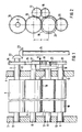
- a blanket cylinder 1 is provided, which is mounted between side walls 3 and 4 by means of a shaft 2.
- a plate cylinder 5 interacts with the blanket cylinder 1 and is supported in the side walls 3, 4 by means of a shaft 6.
- Color is supplied to the plate cylinder 5 by means of an inking cylinder 7, which is also mounted on the side walls 3, 4 by means of a shaft 8.
- an anilox roller 10, which is mounted on the side walls 3, 4 by means of a shaft 9, is provided, which guides the ink from an ink supply device (not shown) to the inking cylinder 7.
- the blanket cylinder 1 and the inking cylinder 7 are each mounted in eccentric bearings 11, 12 so that these parts can be placed against one another under pressure.
- the eccentric bearings 11 and 12 are expediently designed as double eccentric bearings.
- a drive gear 14 is placed, the pitch circle diameter equal to the pitch circle diameter one with it Intermeshing, on the while 6 mounted drive gear 15 is dimensioned.
- the drive gear 14 is driven via two bevel gears 22, 23 by a shaft 24, which is not connected to a drive motor for the printing unit.
- the blanket cylinder 1 is covered with a compressible blanket.
- the diameter of this cylinder is therefore to be dimensioned such that it is slightly smaller than the pitch circle diameter of the gearwheel 14 after the rubber blanket has been placed on it - that is to say in the operational state.
- the diameter of the plate cylinder 5 with the plate placed thereon is slightly larger than the pitch circle diameter of the drive gear 15.
- the diameter differences of the two ready-to-use cylinders 1 and 5 are generally of a magnitude that permit direct engagement of the drive gears 14, 15, the teeth of which are designed to be shifted in profile.
- a drive gear 16 is placed, which is laterally offset from the drive gear 15 so that both gears do not mesh with each other.
- the drive gear 16 is in turn of the same pitch circle diameter as the drive gears 14 and 15.
- the intermediate gear 17 meshes with a further intermediate gear 18, the teeth of which mesh with the teeth of the drive gear 15 in the intermediate gear 17.
- the intermediate gear 18 is in engagement with the drive gear 16 of the inking cylinder 7.
- the inking cylinder 7 is covered with a thick, resilient pad 19, for example a rubber layer made of an incompressible material, its diameter when ready for operation must be noticeably smaller than the diameter of the plate cylinder 5 can be carried out if the surfaces of the two cylinders are to move at the same speed at the point of contact.
- the center distance a between the plate cylinder 5 and the inking cylinder 7 is therefore in the Operating position in which the two cylinders are placed against each other under pressure, so small that an engagement of equally large, meshing drive gears on the shafts 6 and 8 is no longer possible. Due to the offset arrangement of the drive gears 15 and 16, any desired center distance a can be provided.
- the support 19 can be fixed or exchangeable on the inking cylinder 7.
- a further drive gear 20 is firmly attached to the shaft 9. This meshes with a gear 21 which is loosely placed on the shaft 8 next to the drive gear 16 and which is still in engagement with the drive gear 15, that is to say has a smaller pitch circle diameter than the drive gear 16. From the drive gear 20, further elements of the printing unit, such as an ink pump, can be driven.
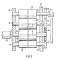
- a blanket cylinder 30, a plate cylinder 31, an inking cylinder 32 and an anilox roller 33 are again provided, which are supported by means of shafts 34, 35, 36, 37 between side walls 38, 39 of the printing unit.
- a drive gear 40 and a bevel gear 41 are fixedly mounted on the shaft 34.
- the bevel gear 41 meshes with a further bevel gear 42 which is driven by a shaft 43 from the main drive of the printing unit.
- the drive gear 40 meshes a drive gear 44 which is firmly seated on the shaft 35 of the plate cylinder. Both gears have the same pitch circle diameter, while the cylinders 30, 31, as in the previous exemplary embodiment, have different diameters.
- the inking cylinder 32 is covered in this embodiment with a pad 48 made of a compressible material, for example layers of rubber, one of which contains air bubbles.
- the diameter of the ready-to-use inking cylinder 32 is larger than that of the ready-to-use plate cylinder 31 so that no grinding movement occurs during operation to get at the point of contact.
- the shaft 36 of the inking cylinder 32 is fixedly connected to a drive electric motor 45. This motor is adjustable so that the inking cylinder 32 can be driven at the same speed as the cylinders 30, 31.
- a gear 46 is loosely rotatable, which meshes on the one hand with the drive gear 44 and on the other hand with a drive gear 47 on the shaft 37 of the anilox roller 33.
- the gear 46 has a larger pitch circle diameter than the drive gear 44 in order to bridge the center distance b, which is so large that it no longer enables a direct engagement of two intermediate gears placed on the shafts 35, 36 of the same pitch circle diameter. This in turn ensures that the drive transmission chain can also easily drive the anilox roller 33 and any downstream elements of the printing unit.
Landscapes
- Inking, Control Or Cleaning Of Printing Machines (AREA)
- Rotary Presses (AREA)
Applications Claiming Priority (2)
| Application Number | Priority Date | Filing Date | Title |
|---|---|---|---|
| DE3922559A DE3922559C2 (de) | 1989-07-08 | 1989-07-08 | Offsetdruckwerk |
| DE3922559 | 1989-07-08 |
Publications (3)
| Publication Number | Publication Date |
|---|---|
| EP0408972A2 true EP0408972A2 (fr) | 1991-01-23 |
| EP0408972A3 EP0408972A3 (en) | 1991-07-24 |
| EP0408972B1 EP0408972B1 (fr) | 1994-03-30 |
Family
ID=6384617
Family Applications (1)
| Application Number | Title | Priority Date | Filing Date |
|---|---|---|---|
| EP90112640A Expired - Lifetime EP0408972B1 (fr) | 1989-07-08 | 1990-07-03 | Dispositif d'impression en offset |
Country Status (5)
| Country | Link |
|---|---|
| US (1) | US5009158A (fr) |
| EP (1) | EP0408972B1 (fr) |
| JP (1) | JPH0342247A (fr) |
| CA (1) | CA2020083C (fr) |
| DE (2) | DE3922559C2 (fr) |
Families Citing this family (10)
| Publication number | Priority date | Publication date | Assignee | Title |
|---|---|---|---|---|
| DE8908243U1 (de) * | 1989-07-06 | 1989-08-17 | MAN Roland Druckmaschinen AG, 6050 Offenbach | Offsetdruckwerk |
| US6374734B1 (en) | 1989-10-05 | 2002-04-23 | Heidelberger Druckmaschinen Ag | Tubular printing blanket |
| US5429048A (en) * | 1989-10-05 | 1995-07-04 | Gaffney; John M. | Offset lithographic printing press |
| JPH0755556B2 (ja) * | 1991-11-16 | 1995-06-14 | 株式会社東京機械製作所 | 分割版胴を有するbb型印刷機 |
| US5345865A (en) * | 1993-04-07 | 1994-09-13 | Dahlgren Usa, Inc. | Hickey removal system |
| DE19519141A1 (de) * | 1995-05-30 | 1996-12-05 | Fischer & Krecke Gmbh & Co | Flexodruckmaschine mit variabler Drucklänge |
| ATE327099T1 (de) * | 2001-03-26 | 2006-06-15 | Koenig & Bauer Ag | Antrieb eines druckwerks |
| DE10144563A1 (de) * | 2001-09-11 | 2003-03-27 | Heidelberger Druckmasch Ag | Druckmaschine und Verfahren zum Betreiben eines Farbwerks |
| CN110962440A (zh) * | 2019-12-06 | 2020-04-07 | 海盐国宏印刷有限公司 | 减少空白间隙的印刷机 |
| CN112339426A (zh) * | 2020-10-28 | 2021-02-09 | 广水市众诚机械有限公司 | 一种用于曲面胶印机的墨站动力系统 |
Family Cites Families (24)
| Publication number | Priority date | Publication date | Assignee | Title |
|---|---|---|---|---|
| US2036835A (en) * | 1933-12-08 | 1936-04-07 | Miehle Printing Press & Mfg | Transfer method and means |
| US2136683A (en) * | 1936-03-21 | 1938-11-15 | Egry Register Co | Printing machine |
| US2301379A (en) * | 1941-04-16 | 1942-11-10 | Willis G Davis | Indexing or synchronizing apparatus |
| US2573090A (en) * | 1947-06-06 | 1951-10-30 | Beasley French & Company Ltd | Pivotal frame structure for rotary printing machine elements |
| US3026798A (en) * | 1960-03-15 | 1962-03-27 | George O Frostad | Printing apparatus |
| US3139826A (en) * | 1961-06-19 | 1964-07-07 | Phillips Petroleum Co | Inking roller for printing machines |
| US3163109A (en) * | 1963-01-21 | 1964-12-29 | Faustel Inc | Interchangeable gear drive means for rotary printing mechanism |
| US3191531A (en) * | 1963-05-24 | 1965-06-29 | Wood Newspaper Mach Corp | Press drive means |
| FR1548329A (fr) * | 1967-06-23 | 1968-12-06 | ||
| US3585932A (en) * | 1968-06-07 | 1971-06-22 | Wallace H Granger | Automatic inking system for rotary newspaper printing press |
| US3724047A (en) * | 1969-03-12 | 1973-04-03 | Minnesota Mining & Mfg | Inking sleeve |
| US3590735A (en) * | 1969-08-26 | 1971-07-06 | Harris Intertype Corp | Ductor roll accelerating mechanism |
| US3587463A (en) * | 1970-05-18 | 1971-06-28 | Wallace H Granger | Simplified circulating inking system for rotary newspaper printing press |
| US3774537A (en) * | 1970-07-15 | 1973-11-27 | Stevens Corp | Rotary offset printing press with removable plate cylinder unit |
| US4000242A (en) * | 1972-07-26 | 1976-12-28 | Crown Zellerbach Corporation | Web material treating system including an inflatable platen roller |
| CA1029240A (fr) * | 1973-08-01 | 1978-04-11 | Harris Corporation | Commande de presse d'imprimerie |
| US3910186A (en) * | 1973-10-15 | 1975-10-07 | American Bank Note Co | Ink supply apparatus for intaglio printing press |
| US3930446A (en) * | 1974-08-23 | 1976-01-06 | Edmund W. Nulton | Duplicator with web master |
| US4223603A (en) * | 1979-01-10 | 1980-09-23 | Didde-Glaser, Inc. | Planetary inker for offset printing press |
| DE3117341C2 (de) * | 1981-05-02 | 1988-07-07 | Albert-Frankenthal Ag, 6710 Frankenthal | Farbwerk |
| DE3232780C2 (de) * | 1981-10-31 | 1986-02-06 | Heidelberger Druckmaschinen Ag, 6900 Heidelberg | Farbwerk für Offsetdruckmaschinen |
| US4445433A (en) * | 1982-04-02 | 1984-05-01 | Menashe Navi | Method and apparatus for variable density inking |
| US4428288A (en) * | 1982-04-26 | 1984-01-31 | Harper Corporation Of America | Adjustable drive system for matching surface speeds of a transfer roll and plate roll and method thereof |
| JPS59204558A (ja) * | 1983-05-09 | 1984-11-19 | Tokyo Kikai Seisakusho:Kk | 平版印刷用メツシユロ−ル |
-
1989
- 1989-07-08 DE DE3922559A patent/DE3922559C2/de not_active Expired - Fee Related
-
1990
- 1990-06-25 US US07/542,879 patent/US5009158A/en not_active Expired - Fee Related
- 1990-06-28 CA CA002020083A patent/CA2020083C/fr not_active Expired - Lifetime
- 1990-07-03 EP EP90112640A patent/EP0408972B1/fr not_active Expired - Lifetime
- 1990-07-03 DE DE90112640T patent/DE59005163D1/de not_active Expired - Fee Related
- 1990-07-09 JP JP2179719A patent/JPH0342247A/ja active Pending
Also Published As
| Publication number | Publication date |
|---|---|
| DE3922559A1 (de) | 1991-01-17 |
| EP0408972B1 (fr) | 1994-03-30 |
| DE59005163D1 (de) | 1994-05-05 |
| DE3922559C2 (de) | 1994-03-24 |
| CA2020083C (fr) | 1992-04-28 |
| EP0408972A3 (en) | 1991-07-24 |
| JPH0342247A (ja) | 1991-02-22 |
| US5009158A (en) | 1991-04-23 |
| CA2020083A1 (fr) | 1991-01-09 |
Similar Documents
| Publication | Publication Date | Title |
|---|---|---|
| DE2436199C2 (de) | Rotations-Offset-Druckmaschine | |
| DE4021895C2 (de) | Druckeinheit einer Offsetdruckmaschine zur Durchführung eines fliegenden Druckplattenwechsels | |
| EP0586881A2 (fr) | Machine à imprimer rotative pour bandes en particulier des bandes en papier épaisses | |
| EP0154836A2 (fr) | Dispositif de répérage pour rotatives d'impression | |
| EP0408972B1 (fr) | Dispositif d'impression en offset | |
| EP0000329B1 (fr) | Entraînement avec moyens d'entraînement pour agiter axialement en va-et-vient les rouleaux balladeurs d'un dispositif d'encrage | |
| EP1286837B1 (fr) | Dispositif d'encrage d'une machine d'impression par rotative | |
| DE2703424B1 (de) | Farbwerk fuer Offset-Druckmaschinen | |
| DE3045611A1 (de) | Justiervorrichtung fuer eine offset-druckpresse | |
| EP0518892B1 (fr) | Mecanisme d'encrage court pour rotative | |
| EP0406737B1 (fr) | Elément d'impression à offset | |
| DE9311113U1 (de) | Eindruckwerk für fliegend wechselnde Eindrucke | |
| EP0428894B1 (fr) | Procédé de préparation d'une unité d'impression et unité d'impression utilisable pour sa mise en oeuvre | |
| DE3344131C2 (de) | Flexodruckwerk für den Verpackungsdruck | |
| DE69400707T2 (de) | Einrichtung zum verstellen des abstandes zwischen zylinderachsen in einer druckmaschine | |
| EP0196018B1 (fr) | Machine d'impression rotative offset avec changement de cliché sans arrêt | |
| DE3510823C1 (de) | Rollenrotations-Offsetdruckmaschine mit einem Druckwerk fuer fliegenden Plattenwechsel | |
| EP1291176B1 (fr) | Machine à imprimer et procédé d'opération d'un dispositif d'encrage | |
| DE3832891A1 (de) | Offset-druckmaschine zum drucken einer kontinuierlichen bahn | |
| DE3407428C1 (de) | Anordnung zum Antrieb einer Walze oder eines Zylinders einer von Buchdruck auf Flexodruck umruestbaren Rotationsdruckmaschine | |
| DE2324684C3 (de) | Färb- oder Feuchtwerksantrieb für Rotationsdruckmaschinen | |
| DE3644445A1 (de) | Druckwerk einer rollenoffset-rotationsdruckmaschine fuer wechselnde eindrucke | |
| DE4101797A1 (de) | Kurzfarbwerk fuer eine rollenrotationsdruckmaschine | |
| DE3130525C2 (de) | Rotationshochdruckmaschine | |
| DE85510C (fr) |
Legal Events
| Date | Code | Title | Description |
|---|---|---|---|
| PUAI | Public reference made under article 153(3) epc to a published international application that has entered the european phase |
Free format text: ORIGINAL CODE: 0009012 |
|
| AK | Designated contracting states |
Kind code of ref document: A2 Designated state(s): CH DE FR GB IT LI SE |
|
| PUAL | Search report despatched |
Free format text: ORIGINAL CODE: 0009013 |
|
| AK | Designated contracting states |
Kind code of ref document: A3 Designated state(s): CH DE FR GB IT LI SE |
|
| 17P | Request for examination filed |
Effective date: 19910521 |
|
| R17P | Request for examination filed (corrected) |
Effective date: 19910621 |
|
| 17Q | First examination report despatched |
Effective date: 19930524 |
|
| ITF | It: translation for a ep patent filed | ||
| GRAA | (expected) grant |
Free format text: ORIGINAL CODE: 0009210 |
|
| AK | Designated contracting states |
Kind code of ref document: B1 Designated state(s): CH DE FR GB IT LI SE |
|
| REF | Corresponds to: |
Ref document number: 59005163 Country of ref document: DE Date of ref document: 19940505 |
|
| ET | Fr: translation filed | ||
| GBT | Gb: translation of ep patent filed (gb section 77(6)(a)/1977) |
Effective date: 19940705 |
|
| EAL | Se: european patent in force in sweden |
Ref document number: 90112640.9 |
|
| PLBE | No opposition filed within time limit |
Free format text: ORIGINAL CODE: 0009261 |
|
| STAA | Information on the status of an ep patent application or granted ep patent |
Free format text: STATUS: NO OPPOSITION FILED WITHIN TIME LIMIT |
|
| 26N | No opposition filed | ||
| PGFP | Annual fee paid to national office [announced via postgrant information from national office to epo] |
Ref country code: GB Payment date: 19980612 Year of fee payment: 9 |
|
| PGFP | Annual fee paid to national office [announced via postgrant information from national office to epo] |
Ref country code: SE Payment date: 19980624 Year of fee payment: 9 |
|
| PGFP | Annual fee paid to national office [announced via postgrant information from national office to epo] |
Ref country code: FR Payment date: 19980629 Year of fee payment: 9 |
|
| PGFP | Annual fee paid to national office [announced via postgrant information from national office to epo] |
Ref country code: DE Payment date: 19980630 Year of fee payment: 9 |
|
| PGFP | Annual fee paid to national office [announced via postgrant information from national office to epo] |
Ref country code: CH Payment date: 19980701 Year of fee payment: 9 |
|
| PG25 | Lapsed in a contracting state [announced via postgrant information from national office to epo] |
Ref country code: GB Free format text: LAPSE BECAUSE OF NON-PAYMENT OF DUE FEES Effective date: 19990703 |
|
| PG25 | Lapsed in a contracting state [announced via postgrant information from national office to epo] |
Ref country code: SE Free format text: THE PATENT HAS BEEN ANNULLED BY A DECISION OF A NATIONAL AUTHORITY Effective date: 19990730 |
|
| PG25 | Lapsed in a contracting state [announced via postgrant information from national office to epo] |
Ref country code: LI Free format text: LAPSE BECAUSE OF NON-PAYMENT OF DUE FEES Effective date: 19990731 Ref country code: FR Free format text: THE PATENT HAS BEEN ANNULLED BY A DECISION OF A NATIONAL AUTHORITY Effective date: 19990731 Ref country code: CH Free format text: LAPSE BECAUSE OF NON-PAYMENT OF DUE FEES Effective date: 19990731 |
|
| GBPC | Gb: european patent ceased through non-payment of renewal fee |
Effective date: 19990703 |
|
| REG | Reference to a national code |
Ref country code: CH Ref legal event code: PL |
|
| EUG | Se: european patent has lapsed |
Ref document number: 90112640.9 |
|
| PG25 | Lapsed in a contracting state [announced via postgrant information from national office to epo] |
Ref country code: DE Free format text: LAPSE BECAUSE OF NON-PAYMENT OF DUE FEES Effective date: 20000503 |
|
| REG | Reference to a national code |
Ref country code: FR Ref legal event code: ST |
|
| PG25 | Lapsed in a contracting state [announced via postgrant information from national office to epo] |
Ref country code: IT Free format text: LAPSE BECAUSE OF NON-PAYMENT OF DUE FEES;WARNING: LAPSES OF ITALIAN PATENTS WITH EFFECTIVE DATE BEFORE 2007 MAY HAVE OCCURRED AT ANY TIME BEFORE 2007. THE CORRECT EFFECTIVE DATE MAY BE DIFFERENT FROM THE ONE RECORDED. Effective date: 20050703 |