EP0406539B1 - Dispositif d'appui de semelle de chaussure pour fixation de ski - Google Patents
Dispositif d'appui de semelle de chaussure pour fixation de ski Download PDFInfo
- Publication number
- EP0406539B1 EP0406539B1 EP90108687A EP90108687A EP0406539B1 EP 0406539 B1 EP0406539 B1 EP 0406539B1 EP 90108687 A EP90108687 A EP 90108687A EP 90108687 A EP90108687 A EP 90108687A EP 0406539 B1 EP0406539 B1 EP 0406539B1
- Authority
- EP
- European Patent Office
- Prior art keywords
- assembly according
- mounting body
- belt
- ski
- groove
- Prior art date
- Legal status (The legal status is an assumption and is not a legal conclusion. Google has not performed a legal analysis and makes no representation as to the accuracy of the status listed.)
- Expired - Lifetime
Links
Images

Classifications
-
- A—HUMAN NECESSITIES
- A63—SPORTS; GAMES; AMUSEMENTS
- A63C—SKATES; SKIS; ROLLER SKATES; DESIGN OR LAYOUT OF COURTS, RINKS OR THE LIKE
- A63C9/00—Ski bindings
- A63C9/001—Anti-friction devices
Definitions
- the invention relates to a sole support device according to the preamble of claim 1.
- the device according to AT-PS 302 129 has side shelves in which bearing axles are mounted, but the band is thicker than the height of these shelves. As a result, when the skier enters the ski boot, the band can be pushed forward over the front edge and thereby deformed.
- the band has the shape of the jacket of a cylinder. In practice, this leads to the fact that when the skier falls over, the movement of the upper run of the band runs along a straight line and therefore deviates from the circular movement of the contact area of the sole of the ski shoe. This has a relative movement from the upper run of the band and from the bottom of the sole of the ski boot and thus one undesirable additional friction, which negatively affects the release of the ski boot.
- the object of the invention is to eliminate this disadvantage and to provide a sole support device in which the movement of the upper run of the band is approximately adapted to the pivoting movement of the ski boot.
- the training according to claim 4 is somewhat more complicated in its structure, but it has the advantage that the tension of the belt and the pressure transmission are brought about by separate elements. This allows these elements to be dimensioned according to the respective tasks.
- the subject of claim 5 simplifies the manufacture of the body from rubber or plastic.
- the measure of claim 7 has the advantage that the tape can be placed on the bearing body and then pushed together with the bearing body onto the support section of the support body.
- the feature of claim 8 improves the elasticity of the bearing body in the region of the deflection points of the band.
- the measure of claim 10 prevents ice formation between the lower run of the band and the top of the ski.
- the assembly of the device is facilitated and the adhesion of the ice crystals, which form in the space between the lower run of the band and the film, is greatly reduced on the base; they can therefore be pushed out of the space with less effort.
- the measure of claim 12 enables a thin configuration of the film.
- the plate is to be made of a hard material, the flexibility of which is to be maintained, however, the feature of claim 14 can be used.
- the measure of claim 15 ensures simple attachment of the plate or film to the support body.
- claims 17 and 18 simplify the structure of the device consisting of film and strips in a sixth embodiment.
- the measure of claim 19 ensures reliable Support of foil and strips within the facility.
- the training according to claim 20 has proven to be particularly advantageous.
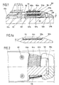
- FIG. 1 is a vertical longitudinal central section through a first embodiment and Fig. 2 is an associated plan view, partly cut along the line II - II in Fig. 1.
- FIGS. 1a and 1b show details of the first embodiment on a larger scale
- FIG. 1c is a schematic plan view of the ski boot with the sole support device.
- 3 and 4 a second embodiment is shown in the vertical longitudinal center section and in plan view. The latter is partially cut along the line IV - IV in Fig. 3.
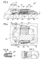
- 5 shows a third embodiment in a partially sectioned top view.
- Fig. 6 is a cross section through a fourth embodiment and Fig. 6a a variant thereof.
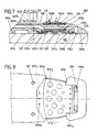
- FIG. 7 is a vertical longitudinal central section through a fifth embodiment and Fig. 8 is a bottom view of the same.
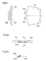
- Fig. 9 the plate and the holder are shown in an exploded state.
- Fig. 10 is a view of the holder in the direction of arrow X in Fig. 11 and Fig. 11 is a section along the line XI - XI in Fig. 10.
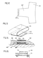
- Fig. 12 shows a sixth embodiment in a plan view of the blank of one Foil and strip of existing piece again before the ends of the strip are welded together.
- Fig. 13 shows the same piece in the diagram, but after the two ends of the strip have been welded. 14, the piece is in the built in the sole support device 600 State reproduced in the vertical longitudinal central section.
- FIG. 15 also shows a detail of a seventh embodiment of the device according to the invention in the vertical longitudinal central section.
- the sole support device shown in FIGS. 1 and 2 is designated 100 in its entirety. It has a support body 102 which can be fastened to the upper side 101a of a ski 101 and in whose central support section 102a, hereinafter also referred to as section, an endless band 104 is mounted in a groove 102b.
- This groove 102b is - seen in plan view of the device 100 - after a circular arc with the radius R, whose center P coincides with the center of the circular arc formed by the rear sole edge of the shoe sole with the radius R1, provided that the sole of the Ski boots comply with the DIN 7880 standard (see Fig. 1c).
- the band 104 which is made of rubber with a Shore A hardness of 50-85, has the shape of the shell of a truncated cone that opens towards the tip of the ski, and has ribs 104b on its upper side, between which grooves 104c are provided.
- the ribs 104b are chamfered at an angle ⁇ between 2 ° and 15 °.
- the angle ⁇ forming a chamfer is between 10 ° and 45 °.
- the bevels of the ribs 104b form in their free end regions with the individual end faces of the band 104 edges which run below the upper boundary edges of the associated side wall of the groove 102b or are flush with these boundary edges. This prevents the band 104 from being pulled out of the groove 102b when the skier enters with his ski boot or when the skier falls forward.
- two wedge-shaped bodies 106 made of rubber or plastic, for example by means of a dovetail guide (see FIG. 1b).
- the band 104 is tensioned with respect to the carrier section 102a by these bodies 106.
- Teflon polytetrafluoroethylene
- the support body 102 is provided in the area in front of the support section 102a with a flat contact surface 102c and is fastened to the top 101a of the ski 101 by means of screws 107, which are indicated in FIGS. 1 and 2.
- the support body 102 is provided with projections 102d directed downward. These projections 102d are inserted into an elongated hole 108a of an end part 108, which also has a flat contact surface 108b.
- a groove 102e which is open at the bottom and to the rear and into which the upper leg 109a of an insert body 109 of U-shaped cross section made of hydrophobic and elastic material, e.g. made of silicone rubber or polyethylene.
- bodies made of a closed-cell foam rubber with a glued-on film made of polytetrafluoroethylene (Teflon) can also be used.
- the lower leg 109b of the insert body 109 is arranged on the ski top 101a between the support body 102 and the end part 108.
- the top 109c of this leg 109b is for example formed by a conical surface or by two adjacent surfaces of a pyramid. If ice crystals form between the lower run of the belt 104 and the insert body 109 during transport or during the journey, these are broken by the skier due to the weight of the skier bending the carrier section 102a downward. If the skier falls over, the ice particles are transported away by means of the lower strand of the belt 104 over the narrow sides of the ski 101.
- FIGS. 3 and 4 The embodiment of a sole support device 200 shown in FIGS. 3 and 4 is similar to that described first, including the strip 210. It differs from this initially in that the band 204 is held under tension by the legs 215a of a U-shaped leg spring 215.
- U-shaped pressure elements 216 are placed on these limbs 215a of the spring 215, which ensure a uniform pressure distribution. These pressure elements 216 are tapered towards the end of the ski.
- the web 215b of the leg spring 215 is provided with a loop 215c and is accommodated in a recess 202f of the support body 202 which is open towards the upper side 201a of the ski. As a result, the web 215b of the leg spring 215 is held immovably with respect to the ski 201.
- the insert body 209 made of plastic, which is approximately U-shaped in cross section, lies under the support section 202a of the support body 202 with its lower leg 209b to form a closed cavity 209d on the Ski top 201a rests.
- the elasticity of the lower leg 209b of the insert body 209 is increased by this cavity 209d.
- This insert body 209 also favors the breaking of the space between the lower run of the band 204 and ice crystals possibly forming on the leg 209b, which, like in the first embodiment, are moved out of the device 200 by means of the transverse movement of the band 204 with the aid of the ribs 204b.
- the sole support device 300 according to FIG. 5 is characterized in that the carrier section 302a is trapezoidal in plan view.
- the two bodies 306 made of rubber or plastic, which are located in the region of the deflection points of the band 304, can be formed with a constant cross section, which considerably simplifies their manufacture.
- the remaining configuration of the device 300 corresponds to that shown in FIGS. 1 and 2.
- the variants of a sole support device 400 shown in FIGS. 6 and 6a are characterized in that a single, in the top view trapezoidal bearing body 420 or 420 'made of rubber or plastic is pushed onto the carrier section 402a, which bearing body 420 or 420' supports the band 404 or the strip 410 over its entire circumference.
- the bearing body 420, 420' In order to enable the bearing body 420, 420 'to be placed on the carrier section 402a, the bearing body 420, 420' has a central recess 420a, 420'a which extends over the entire width, that is to say is continuous.
- two recesses 420b, 420'b and 420c and 420'c are formed in the areas of the deflection points of the band 404, which increase the elasticity of the body 420, 420 'in these areas.
- the recesses 420b, 420'b and 420c, 420'c also allow the material displaced by the tensioned band 404 to be received.
- the bearing body 420 and 420 'according to FIGS. 6 and 6a are similar to each other. They differ only in that the bearing body 420 according to FIG. 6, in Seen cross section, has a rectangular shape with semicircular rounded narrow sides, whereas the bearing body 420 'according to FIG. 6a has an approximately elliptical cross section.
- the fifth sole support device shown in FIGS. 7 to 11 is designated in its entirety by 500. It has a support body 502 which can be fastened to the upper side 501a of a ski 501 and in whose central support section 502a, hereinafter also referred to as section, an endless cylindrical band 504 is mounted in a groove 502b.
- This groove 502b is - seen in plan view of the device 500 - curved according to an arc with a radius R, the center of which coincides with the center of the arc formed by the rear sole edge of the shoe sole, provided that the sole of the ski boot corresponds to the standard DIN 7880 (see Fig. 1c).
- the band 504 which is made of rubber with a Shore A hardness of 50-85, has the shape of the shell of a truncated cone that opens towards the ski tip and is provided on its upper side with ribs 504b, which on the Ski end facing side are chamfered at an angle ⁇ between 2 and 15 °. On the opposite side, facing the ski tip, however, the angle ⁇ forming a chamfer is between 10 and 45 °.
- a strip 510 of polytetrafluoroethylene is located between the band 504 and the carrier section 502a.
- the front cheek shown here in dotted lines is numbered 519.
- the support body 502 is provided in the area in front of the support section 502a with a flat contact surface 502c and is fastened to the top 501a of the ski 501 by means of screws 507, which are only indicated in FIG. 7.
- the support body 502 is provided with projections 502d. These protrusions 502d are inserted into an elongated hole 508a of an end part 508, which is also provided with a flat contact surface 508b.
- the end part 508 also has projections 508c which laterally engage around the carrier section 502a.
- a recess 502e which is open at the bottom and on both sides is recessed therein.
- a plate 509 ' which is covered with a film 509 ⁇ made of polytetrafluoroethylene.
- the plate 509 ' consists of an elastic material with a hardness of up to 30 Shore A. It is provided with recesses 509'g, which increase the flexibility of the plate 509'.
- the plate 509 'and the film 509 ⁇ are provided at both ends with holes 509'c1, 509'c2, 509 ⁇ c1, 509 ⁇ c2, with which they on downward-facing pin 502f of the support body 502 or down pointing pin 508d of the end part 508 can be plugged and on which the plate 509 'and the film 509 ⁇ are held.
- Plate 509 'and film 509 ⁇ are held at one end by means of tabs 509'h, 509 ⁇ h, which have the holes 509'c1 and 509 ⁇ c1, in slots 509'f of a holder 509'd which is rectangular in cross section, the latter horizontal leg also has a number of holes 509'd1.
- the two slots 509'f are arranged symmetrically with respect to the vertical longitudinal median plane of the device 500 (cf. the details in FIGS. 9 to 11).
- the sixth embodiment 600 shown in FIGS. 12 to 14, of which only a detail is shown, is characterized in that the strip 610 made of polytetrafluoroethylene arranged between the band 604 and the carrier section 602a of the support body 602 together with the film 609 ⁇ is made from one piece, which as a blank in plan view has approximately the shape of a "T". In this piece, the two ends of the strip 610 are first welded together. Then the stem of the "T", which is provided at its end with a series of holes 609 ⁇ c2, is bent through 180 °, so that the end of the stem is parallel to those sections of the strip 610, which are the bearing areas for the two Form runs of volume 604.
- the piece consisting of the film 609 ⁇ and the strip 610 is formed to form a body 611 with an elastic material, e.g. Cellular rubber, natural rubber or the like, extrusion-coated.
- the body 611 has an approximately H-shaped shape, as seen in longitudinal section. Subsequently, the body 611 with its two front legs is pushed onto a shoulder 602f of the supporting body 602.
- the seventh embodiment 700 shown in FIG. 15 is characterized in that the piece consisting of the film 709 ⁇ and the strip 710 forms a single component with the body 711.
- the body 711 is also foamed from an elastic material, for example from polytetrafluoroethylene. This one-piece design of the parts 709 ⁇ , 710 and 711 simplifies the assembly of the device.
- a dovetail guide in which the spring is formed from the carrier section and the groove in the body.
- the spring is formed from the carrier section and the groove in the body.
- the components provided at the deflection points of the belt can also be provided with a corresponding coating made of a material with good sliding properties.
- the film can be glued to the plate, or a layer of a low-friction material can be applied to the plate in a separate manufacturing process.
Landscapes
- Footwear And Its Accessory, Manufacturing Method And Apparatuses (AREA)
Claims (21)
- Dispositif d'appui de semelle de chaussure pour fixations de ski, comprenant un corps de support pouvant être assujetti à un ski, et un ruban sans fin qui est guidé dans une gorge du corps de support, transversalement par rapport au sens longitudinal du ski, caractérisé par le fait que le ruban (104 - 604), muni de plusieurs nervures (104b - 604b) et logé par son brin supérieur dans la gorge (102b - 602b) du corps de support (102- 602), revêt la forme de l'enveloppe d'un cône tronqué avant sa mise en place sur le corps de support (102 - 602) ; par le fait que les nervures (104b - 604b) sont biseautées dans leurs régions extrêmes libres et forment une arête respective avec les faces frontales antérieure et postérieure du ruban (104 - 604), lesquelles arêtes - à l'état monté du dispositif (100 - 700) d'appui de semelle - se trouvent au-dessous des arêtes supérieures de délimitation des deux parois latérales de la gorge (102b - 602b), ou sont en affleurement avec lesdites arêtes ; et par le fait que la gorge (102b - 602b) dans laquelle le brin supérieur du ruban (104 - 604) est guidé présente, observée par-dessus, une allure en arc de cercle bombée en direction de la pointe du ski.
- Dispositif selon la revendication 1, caractérisé par le fait que le corps de support (102 - 602) est affecté à la mâchoire avant de la fixation de ski ; et par le fait que, lorsqu'on utilise une chaussure de ski conforme à la norme DIN 7880, le centre (P) de l'arc de cercle de la gorge (102b - 602b) coïncide avec le centre de l'arc de cercle formé par le bord postérieur de la semelle de la chaussure (voir la figure 1c).
- Dispositif selon la revendication 1 ou 2, caractérisé par le fait que deux corps cunéiformes (106) en caoutchouc ou en matière plastique, fixés à la région de support (102a) rectangulaire observée en plan, matérialisent les zones de renvoi du ruban (104) (figures 1 et 2).
- Dispositif selon la revendication 1 ou 2, caractérisé par le fait que le corps de support (202) renferme, en vue de la tension du ruban (204), un ressort (215) à branches aux branches (215a) duquel sont fixés des éléments de pression (216) qui consistent, par exemple, en un matériau doué de bonnes propriétés de glissement, et sont disposés dans les zones de renvoi du ruban (204) (figures 3 et 4).
- Dispositif selon la revendication 1 ou 2, caractérisé par le fait que la région de support (302a) est trapézoïdale observée en plan et porte, sur les deux côtés longitudinaux, des corps (306) en caoutchouc ou en matière plastique dont la section transversale est constante sur toute leur longueur (figure 5).
- Dispositif selon la revendication 3 ou 5, caractérisé par le fait que les corps (106, 306) en caoutchouc ou en matière plastique sont consignés à demeure dans la région de support (102a, 302a) du corps de support (102, 302) au moyen d'un système de guidage à queue d'aronde (figure 1b).
- Dispositif selon la revendication 1 ou 2, caractérisé par le fait qu'un corps de portée (420, 420′) trapézoïdal observé en plan, constitué d'un matériau doué de l'élasticité du caoutchouc et monté sur la région de support (402a) du corps de support (402), présente - observé en coupe transversale - une forme approximativement elliptique ou une forme rectangulaire à petits côtés arrondis en demi-cercle (figures 6 et 6a).
- Dispositif selon la revendication 7, caractérisé par le fait que des échancrures (420b, 420′b et 420c, 420′c) à pourtour fermé sont pratiquées dans le corps de portée (420, 420′), au voisinage des deux zones de renvoi.
- Dispositif selon l'une des revendications 1 - 8, caractérisé par le fait qu'une bande (110 - 410) en polytétrafluoréthylène est disposée à la face supérieure respective de la région de support (102a - 302a) ou du corps de portée (420, 420′).
- Dispositif selon l'une des revendications 1 - 9, caractérisé par le fait qu'une gorge (102e - 402e) ouverte vers le bas et vers l'arrière est ménagée dans le corps de support (102 - 402), au-dessous de la région de support (102a - 402a) de ce dernier, gorge dans laquelle peut être engagée la branche supérieure (109a - 409a) d'un corps prisonnier (109 - 409) de section transversale configurée en U et constitué d'un matériau hydrophobe et élastique, par exemple du caoutchouc siliconé ou du polyéthylène.
- Dispositif selon la revendication 1 ou 2, caractérisé par le fait qu'un évidement (502e, 602e, 702e) ouvert vers le bas et en direction des deux côtés est pratiqué dans le corps de support (502, 602, 702), au-dessous de la région de support (502a, 602a, 702a), cet évidement, dans lequel est guidé le brin inférieur du ruban (504, 604, 704), étant obturé par une feuille (509˝, 609˝, 709˝) en un matériau doué de bonnes propriétés de glissement, par exemple du polytétrafluoréthylène (figures 7 - 15).
- Dispositif selon la revendication 11, caractérisé par le fait que la feuille (509˝) est placée sur une structure sous-jacente (509′) en un matériau élastique, par exemple sur une plaque rectangulaire (figures 7 - 11).
- Dispositif selon la revendication 12, caractérisé par le fait que la structure sous-jacente (509′) est fabriquée en un matériau d'une dureté Shore A de 15 au maximum.
- Dispositif selon la revendication 12, caractérisé par le fait que la structure sous-jacente (509′) est fabriquée en un matériau d'une dureté Shore A de 30 au maximum, et est percée d'échancrures (509′g).
- Dispositif selon l'une des revendications 11 à 14, caractérisé par le fait que la plaque (509′) et la feuille (509˝) comportent, à leurs deux extrémités, des trous (509′c₁, 509′c₂, 509˝c₁, 509˝c₂) par lesquels elles peuvent être respectivement placées sur des tenons (502f) du corps de support (502), ou sur des tenons (508a) d'une pièce d'extrémité (508).
- Dispositif selon la revendication 15, caractérisé par la présence d'une pièce de retenue (509′d) configurée en cornière en coupe transversale ; et par le fait qu'aussi bien la plaque (509′) que la feuille (509˝) sont, à chaque fois, pourvues de deux oreilles (509′h, respectivement 509˝h), lesquelles oreilles présentent un trou respectif (509′c₁, respectivement 509˝c₁) et peuvent être introduites dans des fentes (509′f) de la pièce de retenue (509′d).
- Dispositif selon la revendication 11, caractérisé par le fait que la feuille (609˝, 709˝) est fabriquée d'une seule pièce conjointement à une bande (610, 710) sur laquelle le ruban (604, 704) est monté, cette pièce (609˝, 610 ; 709˝, 710) revêtant sensiblement la forme d'un "T" observée par-dessus, en tant qu'ébauche prédécoupée (figures 12 - 15).
- Dispositif selon la revendication 17, caractérisé par le fait que les deux extrémités de la bande (610, 710) sont solidarisées par soudage (figure 13).
- Dispositif selon la revendication 18, caractérisé par le fait que la pièce (609˝, 610) est enrobée d'un matériau élastique, par exemple du caoutchouc cellulaire, du caoutchouc naturel ou un matériau similaire.
- Dispositif selon la revendication 19, caractérisé par le fait que le corps (609) possède - observé en coupe longitudinale - sensiblement une configuration en "H" et est enfilé, par ses deux branches antérieures, sur un appendice (602f) du corps de support (602).
- Dispositif selon la revendication 17, caractérisé par le fait que la pièce (709˝, 710) et le corps (709) forment une seule et unique partie constitutive (figure 15).
Applications Claiming Priority (4)
| Application Number | Priority Date | Filing Date | Title |
|---|---|---|---|
| AT164489A AT396062B (de) | 1989-07-06 | 1989-07-06 | Sohlenauflageeinrichtung fuer skibindungen |
| AT1644/89 | 1989-07-06 | ||
| AT106/90 | 1990-01-18 | ||
| AT10690A AT397921B (de) | 1990-01-18 | 1990-01-18 | Sohlenauflageeinrichtung für skibindungen |
Publications (2)
| Publication Number | Publication Date |
|---|---|
| EP0406539A1 EP0406539A1 (fr) | 1991-01-09 |
| EP0406539B1 true EP0406539B1 (fr) | 1993-03-03 |
Family
ID=25591470
Family Applications (1)
| Application Number | Title | Priority Date | Filing Date |
|---|---|---|---|
| EP90108687A Expired - Lifetime EP0406539B1 (fr) | 1989-07-06 | 1990-05-09 | Dispositif d'appui de semelle de chaussure pour fixation de ski |
Country Status (3)
| Country | Link |
|---|---|
| US (1) | US5106115A (fr) |
| EP (1) | EP0406539B1 (fr) |
| DE (1) | DE59000954D1 (fr) |
Families Citing this family (3)
| Publication number | Priority date | Publication date | Assignee | Title |
|---|---|---|---|---|
| FR2731161B1 (fr) * | 1995-03-03 | 1997-05-16 | Salomon Sa | Plaque d'appui pour element de fixation de ski |
| FR2816850B1 (fr) * | 2000-11-22 | 2003-02-28 | Look Fixations Sa | Dispositif d'appui d'une chaussure sur un ski |
| FR2865659B1 (fr) * | 2004-01-30 | 2006-07-07 | Salomon Sa | Dispositif de support d'un pied ou d'une chaussure sur un engin de sport |
Family Cites Families (6)
| Publication number | Priority date | Publication date | Assignee | Title |
|---|---|---|---|---|
| US3488990A (en) * | 1967-02-27 | 1970-01-13 | Boniard I Brown | High energy rate forming machine |
| US3490783A (en) * | 1967-06-23 | 1970-01-20 | Ever New Inc | Ski boot heel binding device |
| DE1678278A1 (de) * | 1968-01-22 | 1971-11-11 | Hannes Marker | Vorderbacken fuer Sicherheits-Skibindungen |
| FR2620629B1 (fr) * | 1987-09-18 | 1990-08-31 | Salomon Sa | Dispositif d'appui de la semelle d'une chaussure sur un ski |
| WO1989010777A1 (fr) * | 1988-05-06 | 1989-11-16 | Tmc Corporation | Dispositif de support de semelle |
| FR2631842B1 (fr) * | 1988-05-26 | 1990-09-07 | Salomon Sa | Dispositif d'appui de la partie anterieure de la semelle d'une chaussure sur un ski |
-
1990
- 1990-05-09 EP EP90108687A patent/EP0406539B1/fr not_active Expired - Lifetime
- 1990-05-09 DE DE9090108687T patent/DE59000954D1/de not_active Expired - Fee Related
- 1990-07-06 US US07/549,294 patent/US5106115A/en not_active Expired - Fee Related
Also Published As
| Publication number | Publication date |
|---|---|
| DE59000954D1 (de) | 1993-04-08 |
| US5106115A (en) | 1992-04-21 |
| EP0406539A1 (fr) | 1991-01-09 |
Similar Documents
| Publication | Publication Date | Title |
|---|---|---|
| DE2739207A1 (de) | Skistiefelelement | |
| DD146791A5 (de) | Bindungsanordnung fuer einen skischuh an einem ski | |
| DE3919482C2 (de) | Bindungsvorrichtung, insbesondere für einen Langlaufskischuh | |
| DD238726A5 (de) | Fuehrungsvorrichtung eines schischuhes, und an diese vorrichtung angepasster schuh und schigrundflaeche | |
| AT401599B (de) | Schuh und sohle, insbesondere zum langlaufskifahren | |
| DE2363562A1 (de) | Verbindungsvorrichtung fuer eine skibindung mit einem skikoerper | |
| DE2243229B2 (de) | Laufflächenausbildung für Langlauf-Ski | |
| EP0151975B1 (fr) | Cross-country ski | |
| DE2806403A1 (de) | Verbindungsanordnung zum loesbaren festhalten der bindung an skiern | |
| DE3115618A1 (de) | Halterungsgesamtheit eines langlaufskischuhes auf einem ski | |
| DD239338A5 (de) | Seitliche fuehrungsvorrichtung eines skieschuhes, und an diese vorrichtungangepasster schuh und langlaufski | |
| EP0406539B1 (fr) | Dispositif d'appui de semelle de chaussure pour fixation de ski | |
| DE69600440T2 (de) | Verbesserung für Skis mit mit Stützkanten versehener Schale | |
| DE3834057A1 (de) | Alpiner skischuh | |
| EP0393383B1 (fr) | Plaque de semelle | |
| DE2749731A1 (de) | Skibindung | |
| DE3717108A1 (de) | Sicherheitsskibindung | |
| DE3838586C2 (de) | Seitliche Führungsvorrichtung eines Schuhs auf einem Langlaufski | |
| AT399100B (de) | Abstützungseinrichtung für den vorderen teil der sohle eines schuhs auf einem ski | |
| WO1995032035A1 (fr) | Dispositif destine a influer de facon adequate sur la courbure longitudinale d'un ski | |
| AT396062B (de) | Sohlenauflageeinrichtung fuer skibindungen | |
| DE2838708A1 (de) | Gleitfahrzeug | |
| EP0321687A2 (fr) | Fixation de ski de sécurité | |
| DE1578958A1 (de) | Anordnung an Skibindungen | |
| DE2512799A1 (de) | Ski-sicherheitsbindung |
Legal Events
| Date | Code | Title | Description |
|---|---|---|---|
| PUAI | Public reference made under article 153(3) epc to a published international application that has entered the european phase |
Free format text: ORIGINAL CODE: 0009012 |
|
| AK | Designated contracting states |
Kind code of ref document: A1 Designated state(s): CH DE FR LI |
|
| 17P | Request for examination filed |
Effective date: 19910121 |
|
| RAP1 | Party data changed (applicant data changed or rights of an application transferred) |
Owner name: TMC CORPORATION |
|
| 17Q | First examination report despatched |
Effective date: 19920626 |
|
| RAP1 | Party data changed (applicant data changed or rights of an application transferred) |
Owner name: HTM SPORT- UND FREIZEITGERAETE GESELLSCHAFT M.B.H. |
|
| GRAA | (expected) grant |
Free format text: ORIGINAL CODE: 0009210 |
|
| AK | Designated contracting states |
Kind code of ref document: B1 Designated state(s): CH DE FR LI |
|
| REF | Corresponds to: |
Ref document number: 59000954 Country of ref document: DE Date of ref document: 19930408 |
|
| ET | Fr: translation filed | ||
| PLBE | No opposition filed within time limit |
Free format text: ORIGINAL CODE: 0009261 |
|
| STAA | Information on the status of an ep patent application or granted ep patent |
Free format text: STATUS: NO OPPOSITION FILED WITHIN TIME LIMIT |
|
| RAP2 | Party data changed (patent owner data changed or rights of a patent transferred) |
Owner name: HTM SPORT- UND FREIZEITGERAETE AKTIENGESELLSCHAFT |
|
| REG | Reference to a national code |
Ref country code: CH Ref legal event code: PFA Free format text: HTM SPORT- UND FREIZEITGERAETE AKTIENGESELLSCHAFT |
|
| 26N | No opposition filed | ||
| REG | Reference to a national code |
Ref country code: FR Ref legal event code: CJ |
|
| PGFP | Annual fee paid to national office [announced via postgrant information from national office to epo] |
Ref country code: CH Payment date: 20020416 Year of fee payment: 13 |
|
| PGFP | Annual fee paid to national office [announced via postgrant information from national office to epo] |
Ref country code: DE Payment date: 20020511 Year of fee payment: 13 |
|
| PGFP | Annual fee paid to national office [announced via postgrant information from national office to epo] |
Ref country code: FR Payment date: 20020513 Year of fee payment: 13 |
|
| PG25 | Lapsed in a contracting state [announced via postgrant information from national office to epo] |
Ref country code: LI Free format text: LAPSE BECAUSE OF NON-PAYMENT OF DUE FEES Effective date: 20030531 Ref country code: CH Free format text: LAPSE BECAUSE OF NON-PAYMENT OF DUE FEES Effective date: 20030531 |
|
| PG25 | Lapsed in a contracting state [announced via postgrant information from national office to epo] |
Ref country code: DE Free format text: LAPSE BECAUSE OF NON-PAYMENT OF DUE FEES Effective date: 20031202 |
|
| REG | Reference to a national code |
Ref country code: CH Ref legal event code: PL |
|
| PG25 | Lapsed in a contracting state [announced via postgrant information from national office to epo] |
Ref country code: FR Free format text: LAPSE BECAUSE OF NON-PAYMENT OF DUE FEES Effective date: 20040130 |
|
| REG | Reference to a national code |
Ref country code: FR Ref legal event code: ST |
|
| REG | Reference to a national code |
Ref country code: FR Ref legal event code: TP |