EP0404082A2 - Piezoelektrischer Biegewandler und seine Verwendung - Google Patents
Piezoelektrischer Biegewandler und seine Verwendung Download PDFInfo
- Publication number
- EP0404082A2 EP0404082A2 EP90111599A EP90111599A EP0404082A2 EP 0404082 A2 EP0404082 A2 EP 0404082A2 EP 90111599 A EP90111599 A EP 90111599A EP 90111599 A EP90111599 A EP 90111599A EP 0404082 A2 EP0404082 A2 EP 0404082A2
- Authority
- EP
- European Patent Office
- Prior art keywords
- bending transducer
- metallized
- transducer according
- valve
- layers
- Prior art date
- Legal status (The legal status is an assumption and is not a legal conclusion. Google has not performed a legal analysis and makes no representation as to the accuracy of the status listed.)
- Granted
Links
Images


Classifications
-
- H—ELECTRICITY
- H10—SEMICONDUCTOR DEVICES; ELECTRIC SOLID-STATE DEVICES NOT OTHERWISE PROVIDED FOR
- H10N—ELECTRIC SOLID-STATE DEVICES NOT OTHERWISE PROVIDED FOR
- H10N30/00—Piezoelectric or electrostrictive devices
- H10N30/20—Piezoelectric or electrostrictive devices with electrical input and mechanical output, e.g. functioning as actuators or vibrators
- H10N30/204—Piezoelectric or electrostrictive devices with electrical input and mechanical output, e.g. functioning as actuators or vibrators using bending displacement, e.g. unimorph, bimorph or multimorph cantilever or membrane benders
- H10N30/2041—Beam type
- H10N30/2042—Cantilevers, i.e. having one fixed end
-
- F—MECHANICAL ENGINEERING; LIGHTING; HEATING; WEAPONS; BLASTING
- F16—ENGINEERING ELEMENTS AND UNITS; GENERAL MEASURES FOR PRODUCING AND MAINTAINING EFFECTIVE FUNCTIONING OF MACHINES OR INSTALLATIONS; THERMAL INSULATION IN GENERAL
- F16K—VALVES; TAPS; COCKS; ACTUATING-FLOATS; DEVICES FOR VENTING OR AERATING
- F16K31/00—Actuating devices; Operating means; Releasing devices
- F16K31/004—Actuating devices; Operating means; Releasing devices actuated by piezoelectric means
- F16K31/005—Piezoelectric benders
- F16K31/006—Piezoelectric benders having a free end
-
- H—ELECTRICITY
- H10—SEMICONDUCTOR DEVICES; ELECTRIC SOLID-STATE DEVICES NOT OTHERWISE PROVIDED FOR
- H10N—ELECTRIC SOLID-STATE DEVICES NOT OTHERWISE PROVIDED FOR
- H10N30/00—Piezoelectric or electrostrictive devices
- H10N30/20—Piezoelectric or electrostrictive devices with electrical input and mechanical output, e.g. functioning as actuators or vibrators
- H10N30/204—Piezoelectric or electrostrictive devices with electrical input and mechanical output, e.g. functioning as actuators or vibrators using bending displacement, e.g. unimorph, bimorph or multimorph cantilever or membrane benders
- H10N30/2047—Membrane type
Definitions
- the invention relates to a piezoelectric bending transducer which contains at least one ceramic layer metallized on both sides with piezoelectric properties.
- a piezoelectrically actuable valve which contains in a housing an elongated piezo crystal arrangement clamped on one side, which can be connected to an electrical voltage source.
- the free (movable) end of the piezo crystal arrangement is provided with a sealing body. When sufficient voltage is applied, the piezo crystal moves sideways. The sealing body can thus close a valve channel.
- a disadvantage of this construction is that the application of sealing bodies to the piezo crystal requires an additional operation, and the mass of the bending transducer increases, i.e. its natural resonance is lowered. The bending transducer therefore loses speed. Fewer switching cycles per unit of time can therefore be driven. Since the sealing bodies also take up space, miniaturization of the valve is made more difficult.
- the invention is based on the knowledge that the piezoceramic layer itself is also suitable for sealing a valve channel if the roughness of the surface is less than 0.5 ⁇ m lies. With conventional metallization of the piezoceramic, which is necessary for the later generation of the field strength, however, higher roughness values are obtained.
- a piezoelectric bending transducer which is an essential component a) at least one metallized piezoelectric ceramic layer on both sides, which is polarized so that it undergoes a change in length when a voltage is applied and b) a flat shaped piece connected therewith with approximately the same area dimensions, which suffers no or an opposite linear expansion when a voltage is applied, contains.
- the bending transducer is characterized in that the ceramic layer has on at least one side a non-metallized point with a roughness R a of less than 0.5 ⁇ m. This non-metallized point should be in the zone of maximum deflection when the bending transducer is connected to a voltage source and clamped in a suitable manner.
- the non-metallized point should be slightly larger than the valve channel to be covered.
- the piezo layers are usually metallized by screen printing. In order to prevent the printing paste from flowing down the edge of the layer or to later jump over sparks at the edge, a narrow, approximately 0.3 mm wide strip is usually left unprinted on the edge. Such a strip is not sufficient to cover a valve channel.
- the non-metallized point should have the minimum dimensions of 1 x 1 mm.
- the non-metallized area should therefore be as closely connected as possible.
- the rigid flat shaped piece can be made of any material, e.g. be a metal sheet (no piezoelectric properties) or also a double-sided metallized ceramic layer with piezoelectric properties.
- a metal sheet no piezoelectric properties
- a double-sided metallized ceramic layer with piezoelectric properties.
- the metallized ceramic layer preferably has the shape of an elongated, usually rectangular strip.
- the non-metallized point is then at a narrow end of the strip.
- the strip is clamped on one side at the other end and supplied with voltage.
- Such a strip generally shows the length / width ratio from 1: 2 to 1: 4.
- the non-metallized area should be large enough to cover a rectangle whose length is at least equal to the width and whose width is at least 1 mm, more preferably at least 2 mm.
- the length / width ratio is preferably in the range from 1: 1 to 4: 1.
- a rectangular area of 2.3 x 7.4 mm or 2 x 10 mm or a circular area (diameter 1.5 - 2.5 mm) can be left without metallization on a strip of piezoceramic with an area of 25 x 10 mm.
- Circular areas are better for covering round valve openings. Rectangular areas can be manufactured more easily without metallization for manufacturing reasons.
- the ceramic layer with piezoelectric properties a circular shape and not to arrange the metallized point approximately in the center of the circle Such a bending transducer is clamped on the edge and the area that deflects the most when a voltage is applied is also in the center of the circle.
- a bending transducer which has the shape of an elongated strip
- piezoelectric ceramics e.g. based on lead zirconate titanate
- powders of metal oxides and metal carbonates are used as the starting materials in the majority of cases.
- the product with the final chemical composition is already obtained as a result of a solid-state reaction.
- Other methods such as Coprecipitation from dissolved raw materials are also used.
- the powder is usually subjected to a second grinding to reduce the grain diameter.
- liquid and plasticizer are added to the powder, creating a slip.
- the slurry is then dried by a spray process and pressed dry into the desired shape.
- Organic plasticizers and binders are added to the slip to produce thin parts. Thin, flexible films are obtained from the slip by film casting. The parts are punched out of these foils in the desired shape and sintered after the existing organic substances have been driven out. Then the parts are provided with metal electrodes.
- Piezoceramics with a small thickness can also be produced by pressing a piezomaterial in block form and sawing using suitable saws.
- the ceramic After the sinter firing, the ceramic is present as a polycrystalline body with randomly distributed electrical dipoles, i.e. it shows no piezoelectric activity yet. Only through the process of so-called polarization, i.e. Applying a high electric field, the dipoles are aligned almost completely.
- the orientation is largely retained even after the polarization field is switched off and is associated with a permanent change in the length of the body.
- ceramic layer thicknesses of less than 200 ⁇ m are selected. In this case, when applying a voltage of 24 volts and after clamping the transducer on the metallized Such a deflection at the non-metallized point takes place at the end of the strip such that a valve channel is securely closed.
- the stiffness of the bender is increased while the ceramic layer thicknesses remain the same, since the distance between the ceramic plates and the central neutral zone increases.
- both ceramic foils are generally polarized in the same direction in a bender consisting of only two ceramic layers.
- the bender is controlled so that one piezoceramic layer shortens (the field in the direction of polarization) while the other piezoceramic layer lengthens (the field opposite to the direction of polarization).
- the two outer electrodes of the upper and lower ceramic plate are electrically connected to one another in practical operation and form e.g. the negative connection, while the center electrode forms the positive pole.
- gluing metal sheet with metallized piezoceramic or two sintered, metallized ceramic foils to one another it is also possible to provide non-sintered piezoceramic raw foils with a suitable electrode material, laminate them together and then feed them to the sintering firing, whereby a monolithic piezoceramic bender is formed. Since the electrode material has to withstand sintering temperatures of 900 ° C to 1200 ° C without reacting with the metal oxides of the piezoceramic, only a few materials are suitable for this, e.g. Platinum.
- Gluing sintered, metallized piezoceramic plates with an organic adhesive e.g. a one-component methacrylate adhesive.
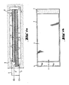
- FIG. 1a shows in cross section a piezoelectric bending transducer in strip form consisting of two ceramic layers (1, 2) metallized on both sides and a conductive intermediate layer, for example a metal sheet (3).
- the layers 1 and 2 are coated on both sides with the thin metallization layer (4).
- at one end of the strip there is a small area (5) on both sides free of metallization. This area serves as a sealing surface in contact with a valve channel (11).
- Bending transducers that have a non-metallized area on only one side can also be used (for certain valves).
- the polarization vector P has the same direction.
- the two layers (1) and (2) are glued to the intermediate layer (3).
- the thin layer of adhesive is not drawn. Power is supplied by wires (6), (7) and (8). At the end that has the power supply, the bending transducer is later mechanically clamped in the holder (9) and contacted at the same time. The length of the two piezo layers is not exactly the same, so that a power supply can be soldered onto the intermediate layer more easily. You could equally well make both ceramic layers of the same length and the metal sheet (3) a little longer.
- Figure (1b) shows the same bending transducer in supervision.
- Figure 2a shows in cross section a bending transducer in strip form, which consists of two piezoceramic layers (1, 2), each of which carries the metallization layer (4). A conductive intermediate layer is missing.
- the metallization layers (4) are connected to the power supply lines (6, 7) at one end. At the opposite end of the strip, a small area (5) of the layer without metallization remains on at least one side.
- the polarization vector P of the two layers (1, 2) is directed in the opposite direction.
- Figure 1b shows the same bending transducer in supervision.
- Figure (3a) shows in cross section an approximately circular bending element and a valve channel to be covered by the bending element. It contains an active piezoceramic layer (1), which has metallization zones (4) on both sides and is glued (adhesive not shown) with a circular metal sheet (3). The metal sheet (3) is mechanically clamped at its edge in a conductive circular holder (9). When the metallization zones (4) are electrically controlled by the current leads (6) and (7), the composite converter is deflected. The deflection is greatest in the center of the circular composite transducer. There is also the metallization-free zone (5), which lies against the opening (10) of the valve channel (11) and ensures its sealing.
- Figure 3b shows the same bending transducer (without clamping) in supervision.
Landscapes
- Engineering & Computer Science (AREA)
- General Engineering & Computer Science (AREA)
- Mechanical Engineering (AREA)
- Electrically Driven Valve-Operating Means (AREA)
- General Electrical Machinery Utilizing Piezoelectricity, Electrostriction Or Magnetostriction (AREA)
- Reciprocating Pumps (AREA)
- Electrophonic Musical Instruments (AREA)
- Piezo-Electric Or Mechanical Vibrators, Or Delay Or Filter Circuits (AREA)
- Piezo-Electric Transducers For Audible Bands (AREA)
Abstract
Description
- Die Erfindung betrifft einen piezoelektrischen Biegewandler der mindestens eine beidseitig metallisierte Keramikschicht mit piezoelektrischen Eigenschaften enthält.
- Aus der DE-OS 36 08 550 ist ein piezo-elektrisch betätigbares Ventil bekannt, das in einem Gehäuse eine langgestreckte einseitig eingespannte Piezokristall-Anordnung enthält, die mit einer elektrischen Spannungsquelle verbindbar ist. Das freie (bewegliche) Ende der Piezokristall-Anordnung ist mit einem Dichtkörper versehen. Bei Anlegen einer ausreichenden Spannung führt der Piezokristall eine seitliche Bewegung aus. Damit kann der Dichtkörper einen Ventilkanal verschließen.
- Nachteilig an dieser Konstruktion ist, daß das Aufbringen von Dichtkörpern auf den Piezokristall einen zusätzlichen Arbeitsgang erfordert, und die Masse des Biegewandlers erhöht, d.h. dessen Eigenresonanz erniedrigt. Der Biegewandler verliert daher an Schnelligkeit. Es können daher weniger Schaltzyklen pro Zeiteinheit gefahren werden. Da die Dichtkörper auch Platz benötigen, wird eine Miniaturisierung des Ventiles erschwert.
- Es bestand daher die Aufgabe, ein Biegeelement für den Einsatz in Ventilen anzugeben, das konstruktiv so ausgelegt ist, daß die angegebenen Nachteile für den Ventilhersteller vermieden werden.
- Die Erfindung geht von der Erkenntnis aus, daß auch die piezokeramische Schicht selbst zum Abdichten eines Ventilkanals geeignet ist, wenn die Rauhigkeit der Oberfläche unter 0,5 µm liegt. Bei einer üblichen Metallisierung der Piezokeramik, die für die spätere Erzeugung der Feldstärke notwendig ist, werden jedoch höhere Rauhigkeitswerte erhalten.
- Es wurde nun ein piezoelektrischer Biegewandler gefunden, der als wesentliche Bestandteile
a) mindestens eine beidseitig metallisierte piezoelektrische Keramikschicht, die so polarisiert ist, daß sie bei Anlegen einer Spannung eine Längenänderung erleidet und
b) ein damit flächig verbundenes steifes Formstück mit etwa gleichen Flächenabmessungen, das bei Anlegen einer Spannung keine oder eine entgegengesetzte Längenausdehnung erleidet,
enthält. Der Biegewandler ist dadurch gekennzeichnet, daß die Keramikschicht auf mindestens einer Seite eine nichtmetallisierte Stelle mit einer Rauhigkeit Ra von unter 0,5 µm aufweist. Diese nicht-metallisierte Stelle soll sich in der Zone maximaler Auslenkung befinden, wenn der Biegewandler mit einer Spannungsquelle verbunden und geeignet eingespannt wird. Die nicht-metallisierte Stelle soll etwas größer sein als der abzudeckende Ventilkanal. Die Metallisierung der Piezoschichten erfolgt üblicherweise durch Siebdruck. Um ein Herabfließen der Druckpaste am Schichtrand oder ein späteres Überspringen von Funken am Rand zu vermeiden, läßt man üblicherweise am Rand einen schmalen, etwa 0,3 mm breiten Streifen unbedruckt. Ein solcher Streifen reicht für die Abdeckung eines Ventilkanals nicht aus. Die nicht-metallisierte Stelle soll die Mindestabmessungen 1 x 1 mm aufweisen. - Je kleiner der Anteil der nicht-metallisierten Stelle an der gesamten beweglichen Fläche ist, umso geringer ist die Einbuße an Auslenkung des Biegewandlers bei Anlegen einer festgelegten Spannung. Der nicht-metallisierte Bereich soll daher möglichst eng zusammenhängend sein.
- Das steife flächige Formstück kann aus einem beliebigen Material bestehen, z.B. ein Metallblech sein (keine piezoelektrischen Eigenschaften) oder ebenfalls eine beidseitige metallisierte Keramikschicht mit piezoelektrischen Eigenschaften. Durch geeignete Polarisierung der verwendeten Piezoschichten und Beachten des Vorzeichens der angelegten Spannung läßt sich erreichen, daß beide Schichten eine entgegengesetzte Längenausdehnung erleiden, was zu einer (geringfügigen?) Krümmung des Biegewandlers, d.h. zu einer Bewegung etwa senkrecht zur Flächenrichtung führt.
- Die metallisierte Keramikschicht hat vorzugsweise die Form eines langgestreckten, meist rechteckigen Streifens. Die nicht-metallisierte Stelle befindet sich dann an einem schmalen Ende des Streifens. Bei einer Verwendung in einem Ventil wird der Streifen am anderen Ende einseitig eingespannt und mit Spannung versorgt.
- Ein solcher Streifen weist i.a. das Verhältnis Länge/Breite von 1:2 bis 1:4 auf. Der nicht-metallisierte Bereich soll so groß sein, daß er ein Rechteck abdeckt, dessen Länge der Breite mindestens gleichkommt und dessen Breite mindestens 1 mm, noch besser mindestens 2 mm beträgt. Vorzugsweise liegt das Verhältnis Länge/Breite im Bereich von 1:1 bis 4:1. Beispielsweise kann man an einem Streifen aus Piezokeramik der Fläche 25 x 10 mm einen rechteckigen Bereich von 2,3 x 7,4 mm oder 2 x 10 mm oder einen kreisförmigen Bereich (Durchmesser 1,5 - 2,5 mm) ohne Metallisierung belassen. Für das Abdecken von runden Ventilöffnungen sind kreisförmige Bereiche besser. Aus fertigungstechnischen Gründen lassen sich rechteckige Bereiche leichter metallisierungsfrei herstellen.
- Es ist ferner möglich, der Keramikschicht mit piezoelektrischen Eigenschaften eine Kreisform zu geben und die nicht metallisierte Stelle etwa in Kreismitte anzuordnen. Ein solcher Biegewandler wird am Rand eingespannt und der Bereich, der bei Anlegen einer Spannung am stärksten auslenkt, befindet sich ebenfalls in der Kreismitte.
- Bei einem Biegewandler, der die Form eines langgestreckten Streifens aufweist, ist es auch möglich, metallisierungsfreie Zonen auf oberster und unterster Keramikplatte des Verbundes vorzusehen. Damit kann erreicht werden, daß in einem Ventil je nach der Auslenkung des Streifens die eine oder die andere Seite einen Ventilkanal abdeckt. Dies erlaubt die Konstruktion eines Ventils mit drei Ventilkanälen und nur einem Biegewandler.
- Zur Herstellung von piezoelektrischer Keramik (z.B. auf der Basis Blei-Zirkonat-Titanat) setzt man als Ausgangsmaterialien in den überwiegenden Fällen Pulver von Metalloxiden und Metallkarbonaten ein. Durch das Kalzinieren erhält man als Ergebnis einer Festkörperreaktion bereits das Produkt mit der chemischen Endzusammensetzung. Andere Verfahren wie z.B. Kopräzipitation aus gelösten Ausgangsrohstoffen werden ebenfalls angewandt.
- Nach dem Kalzinieren wird das Pulver meist einer zweiten Mahlung zur Verkleinerung des Korndurchmessers unterworfen. Während dieser Mahlung wird dem Pulver Flüssigkeit und Plastifikationsmittel zugesetzt, wodurch ein Schlicker entsteht. In der Regel wird dann der Schlicker durch ein Sprühverfahren getrocknet und in die gewünschte Form trockengepreßt.
- Zur Herstellung dünner Teile werden dem Schlicker organische Plastifikationsmittel und Binder zugesetzt. Aus dem Schlicker erhält man durch Foliengießen dünne flexible Folien. Aus diesen Folien werden die Teile in der gewünschten Form ausgestanzt und nach Austreiben der vorhandenen organischen Substanzen gesintert. Danach werden die Teile mit Metallelektroden versehen.
- Piezokeramiken mit geringer Dicke lassen sich auch durch Verpressen eines Piezomaterials in Blockform und Zersägen mittels geeigneter Sägen herstellen.
- Nach dem Sinterbrand liegt die Keramik als polykristalliner Körper mit regellos verteilten elektrischen Dipolen vor, d.h. er zeigt noch keine piezoelektrische Aktivität. Erst durch den Vorgang der sogenannten Polarisation, d.h. Anlegen eines hohen elektrischen Feldes, werden die Dipole nahezu vollständig ausgerichtet.
- Die Ausrichtung bleibt auch nach Abschalten des Polarisationsfeldes weitgehend erhalten und ist mit einer bleibenden Längenänderung des Körpers verbunden.
- Weitere Einzelheiten zur Herstellung keramischer piezokristalliner Materialien sind dem Fachmann z.B. aus Ullmann, 3. Aufl., Enzyclopädie der Technischen Chemie, Bd. 11, S. 421 sowie Bauer, Bühling et al., "Technologie und Anwendung von Ferroelektrika", Akademische Verlagsgesellschaft, Leipzig, bekannt.
- Dadurch, daß keine zusätzlichen Dichtelemente für ein Ventil notwendig sind, entfallen die Arbeitsgänge für die aufwendige Montage der Dichtelemente und die Bauform des Ventils kann sehr klein ausfallen.
- Um auch im Niederspannungsbereich (24 Volt) arbeiten zu können, werden Keramikschichtdicken von unter 200 µm gewählt. In diesem Fall soll bei Anlegen einer Spannung von 24 Volt und nach Einspannung des Wandlers an dem metallisierten Streifenende eine solche Auslenkung an der nicht-metallisierten Stelle erfolgen, daß ein Ventilkanal sicher verschlossen wird.
- Durch die Verwendung einer Zwischenschicht aus einem beliebigen Material, vorzugsweise eines Metallblechs, wird bei gleichbleibenden Keramikschichtdicken die Steifigkeit des Biegers erhöht, da sich der Abstand der Keramikplatten von der mittleren neutralen Zone vergrößert.
- Dadurch erhöht sich die Eigenresonanz und damit die Schnelligkeit des Wandlers, was der Forderung des Anwendersnach immer schnelleren Schaltzyklen entgegen kommt.
- Um rationell fertigen zu können, sind bei einem Bieger, der aus nur zwei Keramikschichten besteht, beide Keramikfolien im allgemeinen gleichsinnig polarisiert. Um die maximale Auslenkung zu erreichen, wird der Bieger so angesteuert, daß sich die eine Piezokeramikschicht verkürzt (das Feld in Polarisationsrichtung) während sich die andere Piezokeramikschicht verlängert (das Feld entgegen der Polarisationsrichtung). Dazu werden im praktischen Betrieb die beiden äußeren Elektroden von oberer und unterer Keramikplatte elektrisch miteinander verbunden und bilden z.B. den Minusanschluß, während die Mittelelektrode den Pluspol bildet.
- Für sehr geringe Spannungen (z.B. 6 Volt) ist es auch möglich, mehrere (x), vorzugsweise 2 bis 8, beidseitig metallisierte, sehr dünne (100 µm und dünner) Piezokeramikschichten unter Verwendung von bis zu (x-1) Zwischenlagen aus leitfähigem Material miteinander zu verkleben, z B. Zwischenlagen aus Blech, Kohlenstoff oder leitfähiger Keramik. Die Keramiken werden dann so polarisiert und elektrisch kontaktiert, daß sich bei einem Bieger mit z.B. 6 aktiven Keramikschichten die oberen drei Schichten verlängern, während sich die unteren drei Schichten verkürzen, wenn die Speisespannung angelegt ist.
- Anstatt Metallblech mit metallisierter Piezokeramik oder zwei gesinterte, metallisierte Keramikfolien miteinander zu verkleben, ist es auch möglich, nicht gesinterte piezokeramische Rohfolien mit einem geeigneten Elektrodenmaterial zu versehen, zusammenzulaminieren und dann dem Sinterbrand zuzuführen, wobei ein monolithischer piezokeramischer Bieger entsteht. Das das Elektrodenmaterial Sintertemperaturen von 900°C bis 1200°C standhalten muß, ohne mit den Metalloxiden der Piezokeramik zu reagieren, eignen sich hierfür nur wenige Materialien, wie z.B. Platin.
- Billiger und im Herstellungsprozeß einfacher ist ein Verkleben von gesinterten, metallisierten Piezokeramikplatten mit einem organischen Kleber, z.B. einem EinkomponentenMethacrylat-Kleber.
- Die Erfindung wird durch die Figuren näher erläutert: Figur 1a zeigt im Querschnitt einen piezoelektrischen Biegewandler in Streifenform bestehend aus zwei beidseitig metallisierten Keramikschichten (1, 2) und einer leitenden zwischenschicht, z.B. einem Metallblech (3). Die Schichten 1 und 2 sind jeweils beidseitig mit der dünnen Metallisierungsschicht (4) überzogen. In der Figur ist an einem Ende des Streifens jeweils auf beiden Seiten ein kleiner Bereich (5) frei von Metallisierung. Dieser Bereich dient als Dichtfläche in Kontakt mit einem Ventilkanal (11). Verwendbar (für bestimmte Ventile) sind auch Biegewandler, die nur auf einer Seite einen nicht-metallisierten Bereich aufweisen.
In den Schichten (1) und (2) hat der Polarisationsvektor P die gleiche Richtung. Die beiden Schichten (1) und (2) sind auf die Zwischenschicht (3) aufgeklebt. Die dünne Kleberschicht ist nicht gezeichnet. Die Stromversorgung erfolgt durch die Drähte (6), (7) und (8). An dem Ende, das die Stromversorgung aufweist, wird später der Biegewandler mechanisch in der Halterung (9) eingespannt und gleichzeitig kontaktiert. Die Länge der beiden Piezoschichten ist nicht ganz gleich, damit an die Zwischenschicht leichter eine Stromzuführung angelötet werden kann. Ebenso gut könnte man beide Keramikschichten gleich lang und das Metallblech (3) etwas länger ausführen.
Figur (1b) zeigt den gleichen Biegewandler in Aufsicht. - Figur 2a zeigt im Querschnitt einen Biegewandler in Streifenform, der aus zwei Piezokeramikschichten (1, 2), die jeweils die Metallsierungsschicht (4) tragen, besteht. Eine leitfähige zwischenschicht fehlt. An einem Ende sind die Metallisierungsschichten (4) mit den Stromzuführungen (6, 7) verbunden. An gegenüberliegendem Ende des Streifens bleibt auf mindestens einer Seite ein kleiner Bereich (5) der Schicht ohne Metallisierung. Der Polarisierungsvektor P der beiden Schichten (1, 2) ist entgegengesetzt gerichtet.
Figur 1b zeigt den gleichen Biegewandler in Aufsicht. - Figur (3a) zeigt im Querschnitt ein etwa kreisförmiges Biegeelement und einen durch das Biegeelement abzudeckenden Ventilkanal. Es enthält eine aktive piezokeramische Schicht (1), die beidseitig Metallisierungszonen (4) aufweist und verklebt ist (Kleber nicht gezeichnet) mit einem kreisrunden Metallblech (3). Das Metallblech (3) ist an seinem Rand mechanisch in einem leitfähigen kreisrunden Halterung (9) eingespannt. Bei elektrischer Ansteuerung der Metallisierungszonen (4) durch die Stromzuführungen (6) und (7) wird der Verbundwandler abgelenkt. Die Auslenkung ist im Zentrum des kreisförmigen Verbundwandlers am größten. Dort befindet sich auch die metallisierungsfreie Zone (5), die sich an die Öffnung (10) des Ventilkanals (11) anlegt und dessen Abdichtung gewährleistet.
Figur 3b zeigt den gleichen Biegewandler (ohne Einspannung) in Aufsicht.
Claims (9)
a) einen im Inneren des Gehäuses einseitig eingespannten piezoelektrischen Biegewandler gemäß Anspruch 1 mit Anschlüssen zum Verbinden mit einer elektrischen Spannungsquelle, der so angeordnet ist, daß bei Abwesenheit einer elektrischen Spannung die nichtmetallisierte Stelle des Streifens den ersten Ventilkanal berührt und verschließt und bei Anlegen einer Spannung diesen Ventilkanal freigibt, und
b) einen zweiten (nicht durch ein Ventil verschlossenen) Ventilkanal, durch den ein unter Druck stehendes Gas in das Innere des Gehäuses gelangen kann,
enthält.
Applications Claiming Priority (4)
| Application Number | Priority Date | Filing Date | Title |
|---|---|---|---|
| DE3920368 | 1989-06-22 | ||
| DE3920368 | 1989-06-22 | ||
| DE3935474 | 1989-10-25 | ||
| DE3935474A DE3935474A1 (de) | 1989-06-22 | 1989-10-25 | Piezoelektrischer biegewandler und seine verwendung |
Publications (3)
| Publication Number | Publication Date |
|---|---|
| EP0404082A2 true EP0404082A2 (de) | 1990-12-27 |
| EP0404082A3 EP0404082A3 (de) | 1991-07-03 |
| EP0404082B1 EP0404082B1 (de) | 1996-01-24 |
Family
ID=25882197
Family Applications (1)
| Application Number | Title | Priority Date | Filing Date |
|---|---|---|---|
| EP90111599A Expired - Lifetime EP0404082B1 (de) | 1989-06-22 | 1990-06-20 | Piezoelektrischer Biegewandler und seine Verwendung |
Country Status (5)
| Country | Link |
|---|---|
| US (1) | US5079472A (de) |
| EP (1) | EP0404082B1 (de) |
| JP (1) | JP3133053B2 (de) |
| AT (1) | ATE133481T1 (de) |
| DE (2) | DE3935474A1 (de) |
Cited By (12)
| Publication number | Priority date | Publication date | Assignee | Title |
|---|---|---|---|---|
| EP0544405A1 (de) * | 1991-10-25 | 1993-06-02 | The Technology Partnership Limited | Piezoelektrisch betätigtes Durchflussregelventil |
| EP0615294A1 (de) * | 1993-03-08 | 1994-09-14 | Ngk Insulators, Ltd. | Piezoelektrische Anordnung |
| DE4410153C1 (de) * | 1994-03-24 | 1995-02-09 | Joucomatic Gmbh | Piezoelektrisch betätigtes Fluidventil |
| EP0656665A1 (de) * | 1993-11-26 | 1995-06-07 | Ngk Insulators, Ltd. | Piezoelektrische Anordnung |
| WO1996026377A1 (en) * | 1995-02-21 | 1996-08-29 | Applied Power Inc. | Piezo-electrically actuated valve |
| WO1997006008A1 (de) * | 1995-08-05 | 1997-02-20 | Rea Elektronik Gmbh | Tintenstrahl-schreibkopf |
| US5630440A (en) * | 1995-02-21 | 1997-05-20 | Applied Power Inc. | Piezo composite sheet actuated valve |
| WO1997046807A1 (en) * | 1996-06-05 | 1997-12-11 | Tore Fors | Force machine |
| DE29722085U1 (de) * | 1997-12-13 | 1998-02-26 | Festo AG & Co, 73734 Esslingen | Ventil |
| DE19649225A1 (de) * | 1996-11-27 | 1998-05-28 | Nass Magnet Gmbh | Ventil |
| WO2009012833A1 (de) | 2007-07-20 | 2009-01-29 | Hoerbiger Automatisierungstechnik Holding Gmbh | Piezoelektrisches ventil |
| DE102013105557A1 (de) * | 2013-05-29 | 2014-12-04 | Michael Förg | Piezoelektrischer Aktor |
Families Citing this family (48)
| Publication number | Priority date | Publication date | Assignee | Title |
|---|---|---|---|---|
| JPH05217121A (ja) * | 1991-11-22 | 1993-08-27 | Internatl Business Mach Corp <Ibm> | 磁気変換器付きチップ等の感熱素子を結合する方法及び装置 |
| DE4411569C1 (de) * | 1994-04-02 | 1995-07-20 | Itw Dynatec Gmbh Klebetechnik | Auftragskopf zur dosierten Abgabe von strömenden Medien |
| US5628411A (en) * | 1994-12-01 | 1997-05-13 | Sortex Limited | Valve devices for use in sorting apparatus ejectors |
| US5780958A (en) * | 1995-11-03 | 1998-07-14 | Aura Systems, Inc. | Piezoelectric vibrating device |
| GB9610819D0 (en) * | 1996-05-22 | 1996-07-31 | Lucas Ind Plc | Valve arrangement |
| DE19627038C2 (de) * | 1996-07-05 | 1998-06-04 | Honeywell Bv | Piezoelektrischer Betätiger |
| US6086041A (en) * | 1997-04-07 | 2000-07-11 | Mccord Winn Textron Inc. | Multi-valve module having a ceramic piezoelectric actuator |
| DE19931990C1 (de) | 1999-07-09 | 2001-01-11 | Festo Ag & Co | Elektroventil |
| EP1106882A3 (de) | 1999-12-09 | 2002-11-13 | Drei-S-Werk Präzisionswerkzeuge GmbH & Co. Fertigungs-KG | Piezoelektrisch betätigbares Ventil |
| DE19961736B4 (de) * | 1999-12-09 | 2006-08-31 | Caterpillar Inc., Peoria | Piezoelektrisch betätigbares Ventil |
| US6357335B1 (en) | 1999-12-23 | 2002-03-19 | Sox Corporation | Pneumatic volume booster for valve positioner |
| US6685164B1 (en) * | 2000-09-11 | 2004-02-03 | Hamai Industries Limited | Control valve and diaphragm for use in the control valve |
| JP2004532743A (ja) * | 2000-10-25 | 2004-10-28 | ワシントン ステート ユニバーシティ リサーチ ファウンデーション | 圧電マイクロトランスデューサ、その使用法および製造法 |
| DE10161888A1 (de) * | 2001-08-14 | 2003-02-27 | Continental Teves Ag & Co Ohg | Piezoelektrisch betätigtes Fluidventil |
| DE10233601A1 (de) | 2002-07-24 | 2004-02-19 | Fraunhofer-Gesellschaft zur Förderung der angewandten Forschung e.V. | Ventil mit kompaktem Betätigungsmechanismus |
| US20040144696A1 (en) | 2003-01-29 | 2004-07-29 | Stewart Mills | Valve device for use in sorting apparatus ejectors |
| KR100519970B1 (ko) * | 2003-10-07 | 2005-10-13 | 삼성전자주식회사 | 밸브리스 마이크로 공기공급장치 |
| DE102004033649A1 (de) * | 2004-07-12 | 2006-02-09 | Siemens Ag | Vorrichtung und Verfahren zum Einstellen einer Orientierung eines Detektorelements einer elektromagnetischen Strahlung und Kamera mit der Vorrichtung |
| US7078850B2 (en) * | 2004-07-20 | 2006-07-18 | Usc Corporation | Piezoelectric power generation device and piezoelectric ceramics member used therefor |
| US7594502B1 (en) | 2005-12-07 | 2009-09-29 | Anderson Joel A | Projectile loading, firing and warning system |
| DE102007034049B3 (de) | 2007-07-19 | 2008-06-12 | Hoerbiger Automatisierungstechnik Holding Gmbh | Piezoelektrisches Ventil |
| DE102007033529A1 (de) | 2007-07-19 | 2009-01-22 | Hoerbiger Automatisierungstechnik Holding Gmbh | Piezoelektrisches Ventil |
| JP2010251726A (ja) * | 2009-03-27 | 2010-11-04 | Ngk Insulators Ltd | 圧電アクチュエータの製造方法 |
| KR101443015B1 (ko) * | 2012-08-17 | 2014-09-22 | 엔지케이 인슐레이터 엘티디 | 복합 기판, 탄성 표면파 디바이스 및 복합 기판의 제조방법 |
| US10371136B2 (en) | 2016-01-29 | 2019-08-06 | Microjet Technology Co., Ltd. | Miniature pneumatic device |
| EP3203080B1 (de) | 2016-01-29 | 2021-09-22 | Microjet Technology Co., Ltd | Pneumatische miniaturvorrichtung |
| US10487820B2 (en) | 2016-01-29 | 2019-11-26 | Microjet Technology Co., Ltd. | Miniature pneumatic device |
| US10388849B2 (en) | 2016-01-29 | 2019-08-20 | Microjet Technology Co., Ltd. | Piezoelectric actuator |
| US10584695B2 (en) | 2016-01-29 | 2020-03-10 | Microjet Technology Co., Ltd. | Miniature fluid control device |
| US10385838B2 (en) | 2016-01-29 | 2019-08-20 | Microjet Technology Co., Ltd. | Miniature fluid control device |
| EP3203079B1 (de) | 2016-01-29 | 2021-05-19 | Microjet Technology Co., Ltd | Piezoelektrischer aktuator |
| US10451051B2 (en) | 2016-01-29 | 2019-10-22 | Microjet Technology Co., Ltd. | Miniature pneumatic device |
| US10529911B2 (en) | 2016-01-29 | 2020-01-07 | Microjet Technology Co., Ltd. | Piezoelectric actuator |
| EP3203077B1 (de) | 2016-01-29 | 2021-06-16 | Microjet Technology Co., Ltd | Piezoelektrischer aktuator |
| EP3203076B1 (de) | 2016-01-29 | 2021-05-12 | Microjet Technology Co., Ltd | Miniaturfluidsteuerungsvorrichtung |
| JP6574452B2 (ja) * | 2016-01-29 | 2019-09-11 | 研能科技股▲ふん▼有限公司 | 小型空気圧動力装置 |
| US10655620B2 (en) | 2016-11-10 | 2020-05-19 | Microjet Technology Co., Ltd. | Miniature fluid control device |
| US10683861B2 (en) | 2016-11-10 | 2020-06-16 | Microjet Technology Co., Ltd. | Miniature pneumatic device |
| US10746169B2 (en) | 2016-11-10 | 2020-08-18 | Microjet Technology Co., Ltd. | Miniature pneumatic device |
| WO2018185821A1 (ja) * | 2017-04-03 | 2018-10-11 | オリンパス株式会社 | 圧電ユニット及び処置具 |
| TWI686536B (zh) * | 2018-02-09 | 2020-03-01 | 研能科技股份有限公司 | 微型流體控制裝置 |
| US11186084B2 (en) | 2018-05-11 | 2021-11-30 | Matthews International Corporation | Electrode structures for micro-valves for use in jetting assemblies |
| US11639057B2 (en) | 2018-05-11 | 2023-05-02 | Matthews International Corporation | Methods of fabricating micro-valves and jetting assemblies including such micro-valves |
| US10994535B2 (en) | 2018-05-11 | 2021-05-04 | Matthews International Corporation | Systems and methods for controlling operation of micro-valves for use in jetting assemblies |
| US11794476B2 (en) | 2018-05-11 | 2023-10-24 | Matthews International Corporation | Micro-valves for use in jetting assemblies |
| AU2019265877B2 (en) | 2018-05-11 | 2024-10-03 | Matthews International Corporation | Systems and methods for sealing micro-valves for use in jetting assemblies |
| MX2022005266A (es) | 2019-11-01 | 2022-08-04 | Matthews Int Corp | Sistemas de deposicion sin contacto que incluyen ensambles de chorro. |
| CN114189787A (zh) * | 2021-11-23 | 2022-03-15 | 中国船舶重工集团公司第七一五研究所 | 一种压力补偿极低频弯曲圆盘换能器 |
Family Cites Families (18)
| Publication number | Priority date | Publication date | Assignee | Title |
|---|---|---|---|---|
| US3152612A (en) * | 1956-09-28 | 1964-10-13 | Gen Electric | Piezoelectric crystal transducer for controlling fluid flow |
| US3152012A (en) * | 1960-12-19 | 1964-10-06 | Ibm | Apparatus for the development of electrostatic images |
| JPS5492307A (en) * | 1977-12-29 | 1979-07-21 | Sony Corp | Driving circuit of electrostrictive converter |
| US4340083A (en) * | 1978-11-30 | 1982-07-20 | Carleton Controls Corporation | Deflectable beam valve |
| JPS6048112B2 (ja) * | 1979-05-02 | 1985-10-25 | ソニー株式会社 | 電気・機械変換素子 |
| DE3025596A1 (de) * | 1980-07-05 | 1982-02-25 | Feldmühle AG, 4000 Düsseldorf | Ventilscheibe aus oxidkeramischem werkstoff |
| US4492360A (en) * | 1982-06-07 | 1985-01-08 | The Lee Company | Piezoelectric valve |
| US4545561A (en) * | 1982-07-30 | 1985-10-08 | Mcdonnell Douglas Corporation | Piezoelectric valve operator |
| AT380934B (de) * | 1983-01-13 | 1986-07-25 | Enfo Grundlagen Forschungs Ag | Elektrisch-pneumatischer signalwandler |
| JPS59186380A (ja) * | 1983-04-06 | 1984-10-23 | Japan Storage Battery Co Ltd | バイモルフ型圧電体変位装置の制御方法 |
| JPS6062170A (ja) * | 1983-09-14 | 1985-04-10 | Teac Co | バイモルフ圧電駆動装置 |
| DE3425290A1 (de) * | 1984-07-10 | 1986-01-16 | Atlas Fahrzeugtechnik GmbH, 5980 Werdohl | Piezokeramische ventilplatte und verfahren zu deren herstellung |
| JPS6123373A (ja) * | 1984-07-11 | 1986-01-31 | Matsushita Electric Ind Co Ltd | 圧電変位素子 |
| AU5992286A (en) * | 1985-06-11 | 1987-01-07 | Arthur D. Little, Inc. | Apparatus for electrical control of rate of fluid flow |
| US4629926A (en) * | 1985-10-21 | 1986-12-16 | Kiwi Coders Corporation | Mounting for piezoelectric bender of fluid control device |
| DE3608550A1 (de) * | 1986-03-14 | 1987-09-17 | Festo Kg | Piezo-elektrisch betaetigbares ventil |
| DE3738630C2 (de) * | 1987-11-13 | 1995-06-08 | Rexroth Mannesmann Gmbh | Elektrohydraulische Druckwandlervorrichtung |
| JP6123569B2 (ja) | 2013-08-15 | 2017-05-10 | 株式会社ソシオネクスト | 電圧発生回路および電圧発生回路の制御方法 |
-
1989
- 1989-10-25 DE DE3935474A patent/DE3935474A1/de not_active Withdrawn
-
1990
- 1990-06-20 AT AT90111599T patent/ATE133481T1/de not_active IP Right Cessation
- 1990-06-20 DE DE59010081T patent/DE59010081D1/de not_active Expired - Fee Related
- 1990-06-20 EP EP90111599A patent/EP0404082B1/de not_active Expired - Lifetime
- 1990-06-22 US US07/541,901 patent/US5079472A/en not_active Expired - Lifetime
- 1990-06-22 JP JP02165494A patent/JP3133053B2/ja not_active Expired - Fee Related
Cited By (17)
| Publication number | Priority date | Publication date | Assignee | Title |
|---|---|---|---|---|
| EP0544405A1 (de) * | 1991-10-25 | 1993-06-02 | The Technology Partnership Limited | Piezoelektrisch betätigtes Durchflussregelventil |
| EP0615294A1 (de) * | 1993-03-08 | 1994-09-14 | Ngk Insulators, Ltd. | Piezoelektrische Anordnung |
| US5594292A (en) * | 1993-11-26 | 1997-01-14 | Ngk Insulators, Ltd. | Piezoelectric device |
| EP0656665A1 (de) * | 1993-11-26 | 1995-06-07 | Ngk Insulators, Ltd. | Piezoelektrische Anordnung |
| DE4410153C1 (de) * | 1994-03-24 | 1995-02-09 | Joucomatic Gmbh | Piezoelektrisch betätigtes Fluidventil |
| WO1995025920A1 (de) * | 1994-03-24 | 1995-09-28 | Joucomatic Gmbh | Piezoelektrisch betätigtes fluidventil |
| US5630440A (en) * | 1995-02-21 | 1997-05-20 | Applied Power Inc. | Piezo composite sheet actuated valve |
| WO1996026377A1 (en) * | 1995-02-21 | 1996-08-29 | Applied Power Inc. | Piezo-electrically actuated valve |
| WO1997006008A1 (de) * | 1995-08-05 | 1997-02-20 | Rea Elektronik Gmbh | Tintenstrahl-schreibkopf |
| WO1997046807A1 (en) * | 1996-06-05 | 1997-12-11 | Tore Fors | Force machine |
| DE19649225A1 (de) * | 1996-11-27 | 1998-05-28 | Nass Magnet Gmbh | Ventil |
| DE29722085U1 (de) * | 1997-12-13 | 1998-02-26 | Festo AG & Co, 73734 Esslingen | Ventil |
| WO2009012833A1 (de) | 2007-07-20 | 2009-01-29 | Hoerbiger Automatisierungstechnik Holding Gmbh | Piezoelektrisches ventil |
| US8220491B2 (en) | 2007-07-20 | 2012-07-17 | Hoerbiger Automatisierungstechnik Holding Gmbh | Piezoelectric valve |
| DE102013105557A1 (de) * | 2013-05-29 | 2014-12-04 | Michael Förg | Piezoelektrischer Aktor |
| DE102013105557B4 (de) * | 2013-05-29 | 2015-06-11 | Michael Förg | Piezoelektrischer Aktor |
| US9806250B2 (en) | 2013-05-29 | 2017-10-31 | Michael Förg | Piezoelectric actuator |
Also Published As
| Publication number | Publication date |
|---|---|
| JPH0365070A (ja) | 1991-03-20 |
| EP0404082B1 (de) | 1996-01-24 |
| DE59010081D1 (de) | 1996-03-07 |
| ATE133481T1 (de) | 1996-02-15 |
| US5079472A (en) | 1992-01-07 |
| JP3133053B2 (ja) | 2001-02-05 |
| EP0404082A3 (de) | 1991-07-03 |
| DE3935474A1 (de) | 1991-01-03 |
Similar Documents
| Publication | Publication Date | Title |
|---|---|---|
| EP0404082B1 (de) | Piezoelektrischer Biegewandler und seine Verwendung | |
| DE69311174T2 (de) | Piezoelektrisches/elektrostriktives Element mit Hilfselektrode zwischen einer piezoelektrischen/elektrostriktiven Schicht und dem Substrat | |
| DE69125762T2 (de) | Piezoelektrisches/elektrostriktives Antriebselement mit keramischem Substrat | |
| DE69505430T2 (de) | Piezoelektrisches/elektrostriktives Dünnfilmelement und Herstellungsverfahren | |
| DE69106431T2 (de) | Piezoelektrischer/elektrostriktiver Antrieb mit mindestens einer piezoelektrischen/elektrostriktiven Schicht. | |
| DE69629283T2 (de) | Ferroelektrischer dünnlagiger monomorpher verbundsensor und verfahren zu seiner herstellung | |
| EP1273051B1 (de) | Piezokeramischer biegewandler sowie verwendung des piezokeramischen biegewandlers | |
| EP0894341B1 (de) | Monolithischer vielschicht-piezoaktor und verfahren zur herstellung | |
| DE2828148C2 (de) | Biegeanordnung | |
| EP1908132B1 (de) | Monolithischer piezoaktor mit drehung der polarisationsrichtung im übergangsbereich sowie verwendung des piezoaktors | |
| DE69014954T2 (de) | Geschichtete Keramikanordnung und Verfahren zu deren Herstellung. | |
| DE19757877A1 (de) | Verfahren zur Herstellung piezoelektrischer Aktoren und piezoelektrischer Aktor | |
| DE2258949A1 (de) | Elektretwandler und verfahren zu seiner herstellung | |
| DE4202650A1 (de) | Piezoelektrische zweielementkristall-einrichtung und verfahren zum treiben einer piezoelektrischen zweielementkristall-einrichtung | |
| DE2845022A1 (de) | Elektronisches schaltungsbauelement | |
| DE112018003429B4 (de) | Piezoelektrisches Bauteil, Sensor und Aktor | |
| DE4005184C2 (de) | ||
| DE102011005990A1 (de) | Piezoelektrischer Stoffverbund, piezoelektrische Keramik, Wandler und Ultraschallmotor | |
| DE3736896A1 (de) | Elektroakustischer wandler | |
| US5841216A (en) | Composite piezoelectric multilayer element and method of manufacturing such an element | |
| DE102008002504A1 (de) | Verfahren zum Herstellen eines gestapelten Piezoaktors sowie Piezoaktor | |
| DE3138249A1 (de) | Kunstharz-impraegnierter piezokeramikkoerper | |
| DE102005033463B3 (de) | Piezoaktor | |
| DE2547606A1 (de) | Piezoelektrischer ultraschallumsetzer | |
| DE1226647B (de) | Elektroakustischer Wandler |
Legal Events
| Date | Code | Title | Description |
|---|---|---|---|
| PUAI | Public reference made under article 153(3) epc to a published international application that has entered the european phase |
Free format text: ORIGINAL CODE: 0009012 |
|
| AK | Designated contracting states |
Kind code of ref document: A2 Designated state(s): AT CH DE FR GB IT LI |
|
| 17P | Request for examination filed |
Effective date: 19901221 |
|
| PUAL | Search report despatched |
Free format text: ORIGINAL CODE: 0009013 |
|
| AK | Designated contracting states |
Kind code of ref document: A3 Designated state(s): AT CH DE FR GB IT LI |
|
| 17Q | First examination report despatched |
Effective date: 19930510 |
|
| GRAA | (expected) grant |
Free format text: ORIGINAL CODE: 0009210 |
|
| AK | Designated contracting states |
Kind code of ref document: B1 Designated state(s): AT CH DE FR GB IT LI |
|
| REF | Corresponds to: |
Ref document number: 133481 Country of ref document: AT Date of ref document: 19960215 Kind code of ref document: T |
|
| REF | Corresponds to: |
Ref document number: 59010081 Country of ref document: DE Date of ref document: 19960307 |
|
| ITF | It: translation for a ep patent filed | ||
| GBT | Gb: translation of ep patent filed (gb section 77(6)(a)/1977) |
Effective date: 19960402 |
|
| ET | Fr: translation filed | ||
| PLBE | No opposition filed within time limit |
Free format text: ORIGINAL CODE: 0009261 |
|
| STAA | Information on the status of an ep patent application or granted ep patent |
Free format text: STATUS: NO OPPOSITION FILED WITHIN TIME LIMIT |
|
| 26N | No opposition filed | ||
| REG | Reference to a national code |
Ref country code: CH Ref legal event code: PUE Owner name: HOECHST CERAMTEC AKTIENGESELLSCHAFT;HOERBIGER FLUI Ref country code: CH Ref legal event code: NV Representative=s name: PATENTANWAELTE SCHAAD, BALASS, MENZL & PARTNER AG |
|
| REG | Reference to a national code |
Ref country code: GB Ref legal event code: 732E |
|
| REG | Reference to a national code |
Ref country code: FR Ref legal event code: TP |
|
| REG | Reference to a national code |
Ref country code: GB Ref legal event code: IF02 |
|
| PGFP | Annual fee paid to national office [announced via postgrant information from national office to epo] |
Ref country code: DE Payment date: 20040527 Year of fee payment: 15 |
|
| PGFP | Annual fee paid to national office [announced via postgrant information from national office to epo] |
Ref country code: GB Payment date: 20040616 Year of fee payment: 15 Ref country code: FR Payment date: 20040616 Year of fee payment: 15 |
|
| PGFP | Annual fee paid to national office [announced via postgrant information from national office to epo] |
Ref country code: CH Payment date: 20040624 Year of fee payment: 15 Ref country code: AT Payment date: 20040624 Year of fee payment: 15 |
|
| PG25 | Lapsed in a contracting state [announced via postgrant information from national office to epo] |
Ref country code: IT Free format text: LAPSE BECAUSE OF NON-PAYMENT OF DUE FEES;WARNING: LAPSES OF ITALIAN PATENTS WITH EFFECTIVE DATE BEFORE 2007 MAY HAVE OCCURRED AT ANY TIME BEFORE 2007. THE CORRECT EFFECTIVE DATE MAY BE DIFFERENT FROM THE ONE RECORDED. Effective date: 20050620 Ref country code: GB Free format text: LAPSE BECAUSE OF NON-PAYMENT OF DUE FEES Effective date: 20050620 Ref country code: AT Free format text: LAPSE BECAUSE OF NON-PAYMENT OF DUE FEES Effective date: 20050620 |
|
| PG25 | Lapsed in a contracting state [announced via postgrant information from national office to epo] |
Ref country code: LI Free format text: LAPSE BECAUSE OF NON-PAYMENT OF DUE FEES Effective date: 20050630 Ref country code: CH Free format text: LAPSE BECAUSE OF NON-PAYMENT OF DUE FEES Effective date: 20050630 |
|
| PG25 | Lapsed in a contracting state [announced via postgrant information from national office to epo] |
Ref country code: DE Free format text: LAPSE BECAUSE OF NON-PAYMENT OF DUE FEES Effective date: 20060103 |
|
| REG | Reference to a national code |
Ref country code: CH Ref legal event code: PL |
|
| PG25 | Lapsed in a contracting state [announced via postgrant information from national office to epo] |
Ref country code: FR Free format text: LAPSE BECAUSE OF NON-PAYMENT OF DUE FEES Effective date: 20060228 |
|
| GBPC | Gb: european patent ceased through non-payment of renewal fee |
Effective date: 20050620 |
|
| REG | Reference to a national code |
Ref country code: FR Ref legal event code: ST Effective date: 20060228 |