EP0403183A2 - Schmelzen von Glas - Google Patents
Schmelzen von Glas Download PDFInfo
- Publication number
- EP0403183A2 EP0403183A2 EP19900306287 EP90306287A EP0403183A2 EP 0403183 A2 EP0403183 A2 EP 0403183A2 EP 19900306287 EP19900306287 EP 19900306287 EP 90306287 A EP90306287 A EP 90306287A EP 0403183 A2 EP0403183 A2 EP 0403183A2
- Authority
- EP
- European Patent Office
- Prior art keywords
- chamber
- glass
- riser
- riser chamber
- temperature
- Prior art date
- Legal status (The legal status is an assumption and is not a legal conclusion. Google has not performed a legal analysis and makes no representation as to the accuracy of the status listed.)
- Withdrawn
Links
Images

Classifications
-
- C—CHEMISTRY; METALLURGY
- C03—GLASS; MINERAL OR SLAG WOOL
- C03B—MANUFACTURE, SHAPING, OR SUPPLEMENTARY PROCESSES
- C03B5/00—Melting in furnaces; Furnaces so far as specially adapted for glass manufacture
- C03B5/04—Melting in furnaces; Furnaces so far as specially adapted for glass manufacture in tank furnaces
-
- C—CHEMISTRY; METALLURGY
- C03—GLASS; MINERAL OR SLAG WOOL
- C03B—MANUFACTURE, SHAPING, OR SUPPLEMENTARY PROCESSES
- C03B5/00—Melting in furnaces; Furnaces so far as specially adapted for glass manufacture
- C03B5/16—Special features of the melting process; Auxiliary means specially adapted for glass-melting furnaces
- C03B5/167—Means for preventing damage to equipment, e.g. by molten glass, hot gases, batches
-
- C—CHEMISTRY; METALLURGY
- C03—GLASS; MINERAL OR SLAG WOOL
- C03B—MANUFACTURE, SHAPING, OR SUPPLEMENTARY PROCESSES
- C03B3/00—Charging the melting furnaces
- C03B3/02—Charging the melting furnaces combined with preheating, premelting or pretreating the glass-making ingredients, pellets or cullet
-
- C—CHEMISTRY; METALLURGY
- C03—GLASS; MINERAL OR SLAG WOOL
- C03B—MANUFACTURE, SHAPING, OR SUPPLEMENTARY PROCESSES
- C03B5/00—Melting in furnaces; Furnaces so far as specially adapted for glass manufacture
- C03B5/02—Melting in furnaces; Furnaces so far as specially adapted for glass manufacture in electric furnaces, e.g. by dielectric heating
- C03B5/027—Melting in furnaces; Furnaces so far as specially adapted for glass manufacture in electric furnaces, e.g. by dielectric heating by passing an electric current between electrodes immersed in the glass bath, i.e. by direct resistance heating
- C03B5/03—Tank furnaces
-
- C—CHEMISTRY; METALLURGY
- C03—GLASS; MINERAL OR SLAG WOOL
- C03B—MANUFACTURE, SHAPING, OR SUPPLEMENTARY PROCESSES
- C03B5/00—Melting in furnaces; Furnaces so far as specially adapted for glass manufacture
- C03B5/16—Special features of the melting process; Auxiliary means specially adapted for glass-melting furnaces
- C03B5/18—Stirring devices; Homogenisation
- C03B5/183—Stirring devices; Homogenisation using thermal means, e.g. for creating convection currents
- C03B5/185—Electric means
-
- C—CHEMISTRY; METALLURGY
- C03—GLASS; MINERAL OR SLAG WOOL
- C03B—MANUFACTURE, SHAPING, OR SUPPLEMENTARY PROCESSES
- C03B5/00—Melting in furnaces; Furnaces so far as specially adapted for glass manufacture
- C03B5/16—Special features of the melting process; Auxiliary means specially adapted for glass-melting furnaces
- C03B5/20—Bridges, shoes, throats, or other devices for withholding dirt, foam, or batch
-
- Y—GENERAL TAGGING OF NEW TECHNOLOGICAL DEVELOPMENTS; GENERAL TAGGING OF CROSS-SECTIONAL TECHNOLOGIES SPANNING OVER SEVERAL SECTIONS OF THE IPC; TECHNICAL SUBJECTS COVERED BY FORMER USPC CROSS-REFERENCE ART COLLECTIONS [XRACs] AND DIGESTS
- Y02—TECHNOLOGIES OR APPLICATIONS FOR MITIGATION OR ADAPTATION AGAINST CLIMATE CHANGE
- Y02P—CLIMATE CHANGE MITIGATION TECHNOLOGIES IN THE PRODUCTION OR PROCESSING OF GOODS
- Y02P40/00—Technologies relating to the processing of minerals
- Y02P40/50—Glass production, e.g. reusing waste heat during processing or shaping
- Y02P40/57—Improving the yield, e-g- reduction of reject rates
Definitions
- This invention relates to glass melting and is particularly directed to glass melting tanks having a throat.
- glass melting tanks To include a melting chamber in which solid batch material is heated to produce molten glass before entering a refining chamber in which the molten glass is at a sufficiently high temperature for refining to occur and thereby reduce defects due to impurities or bubble in the glass.
- the glass passes from a refining chamber through a conditioning zone in which thermal conditioning by controlled cooling is effected prior to glass leaving the tank through an outlet to a forming process.
- Such tanks may be used for continuous production of molten glass and are particularly applicable to the production of high quality glass for use in the production of flat glass.
- molten glass in the melting chamber When solely electric heating is used in a melting chamber of such a tank it is normal for the molten glass in the melting chamber to be covered by a cold top of solid batch material which is progressively melted by heat from electrodes immersed in the glass in the melting chamber.
- the flow path for molten glass from the melting chamber to a refining chamber, when using electric melting may be through a throat located adjacent the base of the melting chamber in order to reduce the probability of unmelted batch material being carried with the molten glass into the refining zone.
- throated melting tanks in the manufacture of flat glass products such as rolled plate glass melted by fossil fuel firing. It is known to provide a riser chamber after the melting chamber. It is also known to provide heating in such a riser chamber.
- serious problems can arise from unwanted corrosion of refractory walls of the riser chamber by the upward flowing glass, particularly where the riser chamber is increasing the temperature of the molten glass to a suitable refining temperature above that of the glass entering from the melting chamber, such as may be necessary in the production of high quality flat glass.
- the flow path of molten glass from the melting chamber to the refining chamber may also be through a throat located adjacent the base of the melting chamber when such a chamber has a batch melting surface as described in our published patent application EP 347 047.
- That melting chamber has means for forming glass batch material into a pile having an elongate sloping surface, the forming means comprising a feed device for feeding batch material to the pile and a pushing device which is located beneath the feed device and is adapted, in use, to push batch material in the pile towards the elongate sloping surface. Batch may be fed to both the upper and lower parts of the pile.
- the batch is melted by radiant heat and flows to a primary homogenising chamber in which it is further heated by radiant heat, electric heat or a combination of the two.
- Glass produced from such a primary homogenising chamber has acceptable levels of solid inclusion faults, but uncceptably high levels of bubble faults for production of high quality flat glass such as float glass.
- Such arrangements may be used for the production of high quality flat glass.
- the present invention provides a method of forming molten glass in a glass melting tank, which method comprises heating batch material in a melting chamber including a primary homogenisation zone to produce molten glass, refining the molten glass in a refining zone and thermally conditioning the glass prior to causing the glass to flow continuously through an outlet from the tank, said method further comprising causing the molten glass to flow through a riser chamber between the primary homogenisation zone and the refining chamber, the glass entering the riser chamber through a throat at the base of the riser chamber and leaving the riser chamber through an outlet at its upper end, the glass being heated in the riser chamber in a central zone spaced from the walls of the riser chamber whereby an inhomogeneous temperature distribution is formed in the glass across the riser chamber and molten glass is caused to flow upwardly in said central zone of the riser chamber with downward glass flow adjacent said chamber walls, the heat input to the glass in the riser chamber being such as to raise the temperature of the glass in the riser chamber and to maintain
- the flow through the riser chamber is toroidal with upward flow in the centre of the toroid and downward flow around the outside of the toroid.
- the method includes sensing the temperature of glass in said throat and sensing the temperature of glass adjacent the base of the riser chamber opposite said throat.
- the method includes cooling upstream and downstream walls of said riser chamber.
- heat is applied to glass in the riser chamber by a plurality of electrodes extending horizontally across the width of the riser chamber and shrouded to prevent heating near to the walls through which they project.
- the horizontal electrodes are mounted in pairs, one above the other as this provides the advantage that heat release is biassed to colder glass near to the lower electrode of the pair which enables an advantageous temperature distribution to be maintained relative to the glass entering the throat.
- This configuration also provides the advantage of maintaining the integrity of the bottom of the riser chamber and allowing for the shrouds to be water cooled which reduces the possibility of glass leaks around the electrodes.
- heat is applied to glass in the riser chamber by one or more horizontal molybdenum grillages supported on horizontal shrouded electrodes.
- the invention also provides a glass melting tank for continuous supply of molten glass to an outlet at a downstream end of the tank, which tank comprises a melting chamber including a primary homogenising chamber at an upstream end of the tank, a refining chamber, a riser chamber between the primary homogenising and refining chambers, said melting chamber having heating means for melting batch material to produce molten glass and an outlet for molten glass adjacent a base of the melting chamber at a downstream end of the chamber, a throat connecting said outlet to an inlet at a base of said riser chamber arranged to receive molten glass from said melting chamber, said riser chamber having an outlet at its upper end coupled to said refining chamber in which the molten glass is refined, said riser chamber having heating means to raise the temperature of the molten glass and chamber walls including an upstream wall adjacent the inlet from the throat and a downstream wall adjacent the outlet to the refining chamber, together with means to cool both said upstream and downstream walls and heating electrodes extending horizontally across the riser chamber for immersion in
- the horizontal electrodes are mounted in pairs, one above the other.
- the horizontal heating electrodes comprise a grillage supported on horizontal shrouded supports.
- the grillage is a rectangular molybdenum grillage supported on short horizontal support electrodes extending through shrouds adjacent the riser wall and most preferably the support electrodes are shaped to retain the grillage in position.
- said riser chamber has upstream and downstream chamber walls spaced respectively from the primary homogenising chamber and refining chamber thereby providing air spaces acting as cooling means for said upstream and downstream walls of the riser chamber.
- a first temperature detector is located adjacent the downstream end of the riser chamber for detecting temperature of molten glass adjacent the base of the riser chamber.
- a second temperature detector is located in said throat for detecting temperature of molten glass passing through the throat.
- the aforesaid methods and apparatus of the invention are particularly applicable to the supply of molten glass for the production of high quality flat glass, including for example float glass.
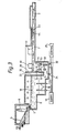
- the glass melting tank comprises a melting chamber 1, a refining chamber 2 and a conditioning chamber 3.
- a riser chamber 4 is located between the melting chamber 1 and the refining chamber 2.
- the tank is suitable for use in producing high quality flat glass such as float glass.
- solid batch material for producing glass is supplied through a system such as a hopper system to the top of the melting chamber 1 so that it falls into a pile having an elongate sloping surface 5 which is melted by flame 6 before flowing through drain hole 7 into primary homogenising chamber 8.
- Heat is supplied to the primary homogenising chamber 8 by flames 9 and by an array of electrodes 17 which are mounted on the base 18 of the primary homogenising chamber and project vertically upwards so as to be immersed in molten glass 16.
- An electrical supply 19 is connected to the electrodes and controlled by a control unit 20.
- Molten glass flows out of the primary homogenising chamber 8 through a centrally located exit 21 in the base 18 of the primary homogenising chamber adjacent a downstream wall 22 of the primary homogenising chamber.
- the exit 21 leads to a submerged throat 23 leading centrally into the lower part of the riser chamber 4.
- a thermocouple 24 is mounted in the base of the throat 23 so as to detect the temperature of molten glass in the throat 23.
- the thermocouple 24 is connected to the control unit 20.
- the riser chamber 4 is provided with an array of electrodes 25 which extend between the side walls 26 of the riser chamber so as to be immersed in the molten glass in the riser chamber.
- the electrodes 25 are arranged to increase the temperature of forward flowing glass so that on leaving the riser 4 the forward flowing glass is at a suitable refining temperature higher than the temperature of the glass entering through the throat 23.
- the electrodes 25 supply heat to a central zone of the riser chamber 4 and are insulated by means of shrouds 30,31 to prevent heating near side walls 26.
- the electrodes 25 are also spaced from upstream wall 28 and downstream wall 29 of the riser chamber. In this way no heat is supplied to the molten glass in the riser chamber in the region of any of the walls of the chamber.
- the electrodes 25 are connected to the power supply 19 and, like the electrodes 17, are arranged to heat the molten glass by the Joule effect.
- a thermocouple 32 is mounted in the base 33 of the riser chamber close to the downstream wall 29 opposite the throat 23 so as to detect the temperature of molten glass at the bottom of the riser chamber in the region close to the downstream wall 29.
- the thermocouple 32 is coupled to the control unit 20 so as to control the power supplied to the electrodes 25 in dependence on the temperature detected by the thermocouples 24 and 32.
- the control 20 provides control of the power supplied to the electrode 25 in the riser chamber 4 independently of the control of the power supplied to the electrode 17 in the molten glass 16.
- each chamber in the melting tank are formed of refractory material so as to withstand the molten glass in the tank.
- the arrangement in the riser chamber 4 is however arranged to minimise corrosion effects from glass passing through the riser chamber from the primary homogenising chamber 8 to the refining chamber 12.
- the upstream wall 28 of the riser chamber is spaced from wall 22 of the primary homogenising chamber so as to provide an air space 35 which acts as a cooling means for the upstream wall 28 of the riser chamber.
- the downstream wall 29 of the riser chamber is separated by an air space 36 from the upstream wall 37 of the refining chamber 12. This air space 36 acts as a cooling means to cool the downstream wall 29 of the riser chamber.
- the two side walls 26 of the riser chamber are not facing heated chambers such as the melting and refining chambers and thereby permit sufficient cooling of the sides of the riser chamber.
- glass entering the riser chamber through the throat 23 may rise in the central flow together with recirculated glass which has descended adjacent the walls of the riser chamber and then ascends in the central upward flow path.
- the glass which rises in the central region is then divided so that some passes into the refining chamber 2 whereas the remainder is recirculated within the riser chamber in the toroidal pattern.
- thermocouples 24 and 32 are operable to control the heat input from the electrodes 25 so as to ensure that there is no build-up of cold glass at the bottom of the riser chamber, particularly starting adjacent the downstream wall 29. Any such build-up of colder glass could gradually restrict the throat 23 causing the forward flowing glass to have a higher velocity on entering the riser chamber and thereby increasing the likelihood of corrosion at the foot of the wall 28 on entering the riser chamber.
- thermocouple 32 is used to ensure that the temperature of molten glass near the base of the riser 4 adjacent the downstream wall 29 and opposite the throat 23 is always higher than the temperature of the glass passing the thermocouple 24 in the throat 23.
- the electrodes 25 are arranged to input heat in the lower part of the riser chamber 4.
- the electrodes are arranged with the bottom electrode of the pair located below the centreline of the throat and the upper electrode located about half way up the riser. By virtue of this, heat release is biassed towards the colder glass around the lower electrode and this provides sufficient heat input at this point to prevent build-up of cold glass at the bottom of the riser 4.
- the water cooled shrouds 30,31 extend horizontally to a distance approximately equal to half the height of the riser 4. If it is desired to use multiple pairs of electrodes then they should be spaced to lie in the middle 80% of the length of the riser 4. The vertical spacing of pairs desirably decreases as they are placed further from upstream wall 28 and closer to downstream wall 29.
- the lower electrodes may be electrically common and the upper electrodes separately controlled to permit power input to be varied easily.
- the shrouds could be made to be air cooled.
- the ratio of the volume V of glass in the riser chamber 14 to the glass load L passing through the tank is preferably in the range 1.25 to 2.5 m3hr/tonne.
- the electrical power required in the riser chamber 14 is typically in the range 40 to 60 kw/m3.
- the power density for the molybdenum electrodes 25 is typically in the range 20 to 40 kw/dm3 of immersed molybdenum electrodes.
- the molten glass After passing into the refining chamber the molten glass is further heated so as to reduce contamination from impurities and also to release bubbles. Additional heat is applied above the molten glass in the riser chamber 4 and refining chamber 2 by gas burners operating through ports such as those marked at 40 and 41.
- the glass melting tank is formed with a tapered waist 43 adjacent the junction between the refining chamber 2 and conditioning chamber 3.
- a barrier in the form of a transverse water-cooled pipe 44 extends across the waist and is submerged in the the molten glass.
- the pipe is water-cooled so as to reduce the temperature of glass entering the thermal conditioning zone 3 and reduces the rate of flow of hot surface glass out of the refining chamber 2 thereby ensuring satisfactory refining.
- An array of stirrers 45 which may also be water-cooled are located adjacent the water pipe 44 on the downstream side of the pipe.
- the pipe 44 and stirrers 45 may improve the temperature and homogeneity of the glass entering the conditioning zone 3.
- the zone 3 is not normally heated and the temperature of the glass is gradually reduced on flowing through the conditioning zone 3 towards an outlet 48 leading to a glass forming process.
- the riser chamber 4 in this example is used to raise the temperature of forward flowing glass and is not used for controlled cooling.
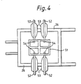
- the riser 4 is heated by rectangular molybdenum grillages 50 and 51 which are each mounted on four horizontal electrodes 52 which pass through side walls 26 and are shrouded by water cooled shrouds 53.
- the electrodes have upturned extremities 54 which engage and retain the grillage 50,51.
- the refining and conditioning zones of the unit may be designed to operate with various flow regimes in the molten glass.
- molten glass could be fed to the riser chamber through a plurality of throats, for example from a plurality of melting chambers. Such throats may be through different walls of the riser chamber which need not be of rectangular form and could have a number of walls other than four.
- a plurality of riser chambers 4 may be provided each supplied by a respective throat.
- a plurality of risers may be used and may be connected to a common conditioning chamber.
Landscapes
- Chemical & Material Sciences (AREA)
- Engineering & Computer Science (AREA)
- Materials Engineering (AREA)
- Organic Chemistry (AREA)
- Chemical Kinetics & Catalysis (AREA)
- Electrochemistry (AREA)
- Physics & Mathematics (AREA)
- Thermal Sciences (AREA)
- Glass Melting And Manufacturing (AREA)
- Vertical, Hearth, Or Arc Furnaces (AREA)
- Furnace Details (AREA)
- Processing Of Solid Wastes (AREA)
- Glass Compositions (AREA)
Applications Claiming Priority (2)
| Application Number | Priority Date | Filing Date | Title |
|---|---|---|---|
| GB8913539 | 1989-06-13 | ||
| GB898913539A GB8913539D0 (en) | 1989-06-13 | 1989-06-13 | Glass melting |
Publications (2)
| Publication Number | Publication Date |
|---|---|
| EP0403183A2 true EP0403183A2 (de) | 1990-12-19 |
| EP0403183A3 EP0403183A3 (de) | 1992-03-04 |
Family
ID=10658340
Family Applications (2)
| Application Number | Title | Priority Date | Filing Date |
|---|---|---|---|
| EP19900306287 Withdrawn EP0403183A3 (de) | 1989-06-13 | 1990-06-08 | Schmelzen von Glas |
| EP90306288A Expired - Lifetime EP0403184B1 (de) | 1989-06-13 | 1990-06-08 | Schmelzen von Glas |
Family Applications After (1)
| Application Number | Title | Priority Date | Filing Date |
|---|---|---|---|
| EP90306288A Expired - Lifetime EP0403184B1 (de) | 1989-06-13 | 1990-06-08 | Schmelzen von Glas |
Country Status (28)
| Country | Link |
|---|---|
| EP (2) | EP0403183A3 (de) |
| JP (1) | JPH07106913B2 (de) |
| KR (1) | KR0129770B1 (de) |
| CN (1) | CN1022905C (de) |
| AR (1) | AR243485A1 (de) |
| AT (1) | ATE120723T1 (de) |
| AU (1) | AU632331B2 (de) |
| BG (1) | BG60861B1 (de) |
| BR (1) | BR9002798A (de) |
| CA (1) | CA2018740C (de) |
| CZ (1) | CZ285223B6 (de) |
| DD (1) | DD298373A5 (de) |
| DE (1) | DE69018317T2 (de) |
| ES (1) | ES2073527T3 (de) |
| FI (1) | FI91520C (de) |
| GB (3) | GB8913539D0 (de) |
| HU (1) | HU215945B (de) |
| IE (1) | IE67772B1 (de) |
| IN (1) | IN175675B (de) |
| NO (1) | NO178658C (de) |
| NZ (1) | NZ234012A (de) |
| PL (1) | PL166463B1 (de) |
| PT (1) | PT94349B (de) |
| RO (1) | RO106124B1 (de) |
| RU (1) | RU1838253C (de) |
| TR (1) | TR27116A (de) |
| YU (1) | YU47355B (de) |
| ZA (1) | ZA904578B (de) |
Cited By (5)
| Publication number | Priority date | Publication date | Assignee | Title |
|---|---|---|---|---|
| DE4424951A1 (de) * | 1994-07-14 | 1996-01-18 | Flachglas Ag | Verfahren und Vorrichtung zum Verglasen von Reststoffen |
| FR2787784A1 (fr) * | 1998-12-23 | 2000-06-30 | Stein Heurtey | Perfectionnements apportes aux fours de fusion et d'affinage de verre |
| EP1055645A3 (de) * | 1999-05-28 | 2001-05-23 | Schott Glas | Glasschmelzwanne und Verfahren zum Schmelzen von Glas |
| EP4345069A1 (de) * | 2023-09-29 | 2024-04-03 | Schott Ag | Gefässsystem zur herstellung und läuterung einer glasschmelze und verfahren zur herstellung und läuterung einer glasschmelze |
| WO2025068384A1 (en) * | 2023-09-29 | 2025-04-03 | Schott Ag | A vessel system for producing and refining a glass melt, and method for producing and refining a glass melt |
Families Citing this family (19)
| Publication number | Priority date | Publication date | Assignee | Title |
|---|---|---|---|---|
| US6506792B1 (en) | 1997-03-04 | 2003-01-14 | Sterix Limited | Compounds that inhibit oestrone sulphatase and/or aromatase and methods for making and using |
| TR199902155T1 (xx) * | 1998-01-09 | 2000-04-21 | Saint-Gobain Vitrage | Cam haline gelebilen maddelerin ergitilmesi, rafinaj�na y�nelik metod. |
| KR20020046075A (ko) * | 2000-12-12 | 2002-06-20 | 곽영훈 | 유리 용융로 |
| KR20030005482A (ko) * | 2001-07-09 | 2003-01-23 | 김명식 | 유리 제조용 전기용해로 및 이 유리 제조용 전기용해로를이용한 유리제조방법 |
| CN100569680C (zh) * | 2003-10-20 | 2009-12-16 | 日本电气硝子株式会社 | 玻璃组合物及玻璃物品的制造方法 |
| CN1902045B (zh) * | 2003-11-28 | 2011-04-13 | 康宁股份有限公司 | 低翘曲平坦玻璃的制造方法 |
| US7854144B2 (en) * | 2005-07-28 | 2010-12-21 | Corning Incorporated | Method of reducing gaseous inclusions in a glass making process |
| US7454925B2 (en) * | 2005-12-29 | 2008-11-25 | Corning Incorporated | Method of forming a glass melt |
| CN101838098B (zh) * | 2010-03-30 | 2013-02-13 | 株洲旗滨集团股份有限公司 | 一种新型全氧燃烧玻璃熔窑 |
| JP5730806B2 (ja) * | 2012-04-05 | 2015-06-10 | AvanStrate株式会社 | ガラス基板の製造方法 |
| JP5719797B2 (ja) * | 2012-04-06 | 2015-05-20 | AvanStrate株式会社 | ガラス板の製造方法及びガラス板の製造装置 |
| JP5731437B2 (ja) * | 2012-04-06 | 2015-06-10 | AvanStrate株式会社 | ガラス板の製造方法 |
| WO2014116549A1 (en) * | 2013-01-24 | 2014-07-31 | Corning Incorporated | Process and apparatus for refining molten glass |
| JP6749123B2 (ja) * | 2016-03-31 | 2020-09-02 | AvanStrate株式会社 | ガラス基板の製造方法、及び、ガラス基板の製造装置 |
| EP3760595A1 (de) * | 2019-07-04 | 2021-01-06 | International Partners in Glass Research (IPGR) e.V. | Glasschmelzofen |
| KR102172552B1 (ko) * | 2020-06-26 | 2020-11-02 | 이준호 | 열교환 시스템을 이용한 직접 가열식 용융 장치 |
| JP7698237B2 (ja) * | 2020-12-02 | 2025-06-25 | 日本電気硝子株式会社 | ガラス溶融炉監視方法、及びガラス物品製造方法 |
| DE102022110617A1 (de) | 2022-05-02 | 2023-11-02 | Saint-Gobain SEKURIT Deutschland GmbH | Verfahren zur Herstellung von Wasserstoff bei einer mit Wasserstoff betriebenen Glasschmelzwanne |
| CN117164214B (zh) * | 2023-08-03 | 2024-08-13 | 中建材玻璃新材料研究院集团有限公司 | 一种高世代显示玻璃生产工艺 |
Family Cites Families (12)
| Publication number | Priority date | Publication date | Assignee | Title |
|---|---|---|---|---|
| BE390369A (de) * | 1932-05-05 | |||
| BE409868A (de) * | 1934-06-13 | |||
| GB822818A (en) * | 1956-05-14 | 1959-11-04 | Libbey Owens Ford Glass Co | Method and apparatus for melting glass |
| FR1502663A (fr) * | 1966-05-17 | 1967-11-24 | Saint Gobain | Procédé de fabrication du verre |
| DE2403476B2 (de) * | 1974-01-25 | 1977-11-24 | Sorg Gmbh & Co Kg, 8771 Pflochsbach | Verfahren zum faerben eines glasstromes und glasfaerbezelle zur durchfuehrung des verfahrens |
| US4424071A (en) * | 1982-09-27 | 1984-01-03 | Toledo Engineering Co., Inc. | Molten mass temperature conditioner |
| DD216710A1 (de) * | 1983-07-06 | 1984-12-19 | Inst Techn Glas Jena Veb | Glasschmelzwanne |
| FR2550523B1 (fr) * | 1983-08-09 | 1986-07-25 | Saint Gobain Vitrage | Procede et dispositif de fusion, d'affinage et d'homogeneisation de verre, et leurs applications |
| ATE31524T1 (de) * | 1983-09-29 | 1988-01-15 | Owens Corning Fiberglass Corp | Elektrisches schmelzen von erstarrtem glas in einer schmelzanlage. |
| FR2599734B1 (fr) * | 1986-06-06 | 1992-06-05 | Saint Gobain Rech | Technique de fusion electrique du verre |
| DE3718276A1 (de) * | 1987-05-30 | 1988-12-08 | Sorg Gmbh & Co Kg | Glasschmelzofen |
| FR2619560B1 (fr) * | 1987-08-18 | 1992-10-30 | Saint Gobain Vitrage | Procede et dispositif d'elaboration de verre fondu |
-
1989
- 1989-06-13 GB GB898913539A patent/GB8913539D0/en active Pending
-
1990
- 1990-06-06 IE IE203390A patent/IE67772B1/en not_active IP Right Cessation
- 1990-06-07 TR TR00555/90A patent/TR27116A/xx unknown
- 1990-06-08 EP EP19900306287 patent/EP0403183A3/de not_active Withdrawn
- 1990-06-08 AU AU57040/90A patent/AU632331B2/en not_active Ceased
- 1990-06-08 GB GB9012835A patent/GB2235445A/en not_active Withdrawn
- 1990-06-08 AT AT90306288T patent/ATE120723T1/de not_active IP Right Cessation
- 1990-06-08 EP EP90306288A patent/EP0403184B1/de not_active Expired - Lifetime
- 1990-06-08 DE DE69018317T patent/DE69018317T2/de not_active Expired - Fee Related
- 1990-06-08 GB GB9012836A patent/GB2232753A/en not_active Withdrawn
- 1990-06-08 ES ES90306288T patent/ES2073527T3/es not_active Expired - Lifetime
- 1990-06-11 NZ NZ234012A patent/NZ234012A/xx unknown
- 1990-06-11 NO NO902572A patent/NO178658C/no unknown
- 1990-06-11 CA CA002018740A patent/CA2018740C/en not_active Expired - Fee Related
- 1990-06-12 BG BG92205A patent/BG60861B1/bg unknown
- 1990-06-12 CN CN90104312A patent/CN1022905C/zh not_active Expired - Fee Related
- 1990-06-12 YU YU114090A patent/YU47355B/sh unknown
- 1990-06-12 PT PT94349A patent/PT94349B/pt not_active IP Right Cessation
- 1990-06-12 IN IN457MA1990 patent/IN175675B/en unknown
- 1990-06-12 DD DD90341562A patent/DD298373A5/de not_active IP Right Cessation
- 1990-06-12 AR AR90317076A patent/AR243485A1/es active
- 1990-06-12 KR KR1019900008580A patent/KR0129770B1/ko not_active Expired - Fee Related
- 1990-06-12 HU HU903819A patent/HU215945B/hu not_active IP Right Cessation
- 1990-06-12 RU SU904830236A patent/RU1838253C/ru active
- 1990-06-13 BR BR909002798A patent/BR9002798A/pt not_active IP Right Cessation
- 1990-06-13 ZA ZA904578A patent/ZA904578B/xx unknown
- 1990-06-13 FI FI902962A patent/FI91520C/fi not_active IP Right Cessation
- 1990-06-13 PL PL90285637A patent/PL166463B1/pl unknown
- 1990-06-13 RO RO145335A patent/RO106124B1/ro unknown
- 1990-06-13 CZ CS902939A patent/CZ285223B6/cs unknown
- 1990-06-13 JP JP2154986A patent/JPH07106913B2/ja not_active Expired - Lifetime
Cited By (5)
| Publication number | Priority date | Publication date | Assignee | Title |
|---|---|---|---|---|
| DE4424951A1 (de) * | 1994-07-14 | 1996-01-18 | Flachglas Ag | Verfahren und Vorrichtung zum Verglasen von Reststoffen |
| FR2787784A1 (fr) * | 1998-12-23 | 2000-06-30 | Stein Heurtey | Perfectionnements apportes aux fours de fusion et d'affinage de verre |
| EP1055645A3 (de) * | 1999-05-28 | 2001-05-23 | Schott Glas | Glasschmelzwanne und Verfahren zum Schmelzen von Glas |
| EP4345069A1 (de) * | 2023-09-29 | 2024-04-03 | Schott Ag | Gefässsystem zur herstellung und läuterung einer glasschmelze und verfahren zur herstellung und läuterung einer glasschmelze |
| WO2025068384A1 (en) * | 2023-09-29 | 2025-04-03 | Schott Ag | A vessel system for producing and refining a glass melt, and method for producing and refining a glass melt |
Also Published As
Similar Documents
| Publication | Publication Date | Title |
|---|---|---|
| EP0403183A2 (de) | Schmelzen von Glas | |
| US5194081A (en) | Glass melting process | |
| CA1060655A (en) | Manufacture of glass | |
| US6085551A (en) | Method and apparatus for manufacturing high melting point glasses with volatile components | |
| US7454925B2 (en) | Method of forming a glass melt | |
| KR100434212B1 (ko) | 유리질재료를용융하기위한장치 | |
| EP0186972B1 (de) | Glasschmelzwannenöfen und darin benutzte feuerfeste Materialien | |
| US4818265A (en) | Barrier apparatus and method of use for melting and refining glass or the like | |
| KR100590694B1 (ko) | 무기화합물, 특히 유리 및 유리 세라믹의 연속 용융 및 정련을 위한 장치 및 그 조작방법 | |
| US5370723A (en) | Glass melting furnace with control of the glass flow in the riser | |
| US4906272A (en) | Furnace for fining molten glass | |
| US4200448A (en) | Glass manufacture | |
| US4317669A (en) | Glass melting furnace having a submerged weir | |
| FI83760C (fi) | Foerfarande och anordning foer framstaellning av glas eller liknande. | |
| FI59578B (fi) | Foerfarande foer konditionerande av smaelt glasmassa och en glassmaeltningsugn | |
| KR800000199B1 (ko) | 유리 제조장치 | |
| HRP920861A2 (en) | Glass melting |
Legal Events
| Date | Code | Title | Description |
|---|---|---|---|
| PUAI | Public reference made under article 153(3) epc to a published international application that has entered the european phase |
Free format text: ORIGINAL CODE: 0009012 |
|
| AK | Designated contracting states |
Kind code of ref document: A2 Designated state(s): AT BE CH DE DK ES FR GB GR IT LI LU NL SE |
|
| RIN1 | Information on inventor provided before grant (corrected) |
Inventor name: MARTLEW, DAVID Inventor name: WHITFIELD, PETER JAMES |
|
| RIN1 | Information on inventor provided before grant (corrected) |
Inventor name: WHITFIELD, PETER JAMES Inventor name: MARTLEW, DAVID |
|
| PUAL | Search report despatched |
Free format text: ORIGINAL CODE: 0009013 |
|
| AK | Designated contracting states |
Kind code of ref document: A3 Designated state(s): AT BE CH DE DK ES FR GB GR IT LI LU NL SE |
|
| 17P | Request for examination filed |
Effective date: 19920725 |
|
| 17Q | First examination report despatched |
Effective date: 19930524 |
|
| STAA | Information on the status of an ep patent application or granted ep patent |
Free format text: STATUS: THE APPLICATION IS DEEMED TO BE WITHDRAWN |
|
| 18D | Application deemed to be withdrawn |
Effective date: 19931004 |