EP0401878B1 - Tintenband für Sublimierungsübertragung auf Papier - Google Patents
Tintenband für Sublimierungsübertragung auf Papier Download PDFInfo
- Publication number
- EP0401878B1 EP0401878B1 EP90114883A EP90114883A EP0401878B1 EP 0401878 B1 EP0401878 B1 EP 0401878B1 EP 90114883 A EP90114883 A EP 90114883A EP 90114883 A EP90114883 A EP 90114883A EP 0401878 B1 EP0401878 B1 EP 0401878B1
- Authority
- EP
- European Patent Office
- Prior art keywords
- ink ribbon
- layer
- film
- resin
- hard copy
- Prior art date
- Legal status (The legal status is an assumption and is not a legal conclusion. Google has not performed a legal analysis and makes no representation as to the accuracy of the status listed.)
- Expired - Lifetime
Links
Images


Classifications
-
- B—PERFORMING OPERATIONS; TRANSPORTING
- B41—PRINTING; LINING MACHINES; TYPEWRITERS; STAMPS
- B41M—PRINTING, DUPLICATING, MARKING, OR COPYING PROCESSES; COLOUR PRINTING
- B41M5/00—Duplicating or marking methods; Sheet materials for use therein
- B41M5/26—Thermography ; Marking by high energetic means, e.g. laser otherwise than by burning, and characterised by the material used
- B41M5/40—Thermography ; Marking by high energetic means, e.g. laser otherwise than by burning, and characterised by the material used characterised by the base backcoat, intermediate, or covering layers, e.g. for thermal transfer dye-donor or dye-receiver sheets; Heat, radiation filtering or absorbing means or layers; combined with other image registration layers or compositions; Special originals for reproduction by thermography
- B41M5/42—Intermediate, backcoat, or covering layers
- B41M5/44—Intermediate, backcoat, or covering layers characterised by the macromolecular compounds
Definitions
- the present invention relates to an ink ribbon for a sublimation transfer type hard copy used to produce a hard copy of a still picture image such as a picture image taken by a video camera or a television picture image.
- Fig. 1 shows an example of a prior art printer for a sublimation transfer type hard copy.
- This printer comprises a platen 2 having wound therearound a printing paper 1 and which is rotatable in the direction shown by an arrow a and a thermal print head 4 which is urged against the platen across an ink ribbon 3 for use in thermal transfer recording.
- the ink ribbon 3 for use in thermal transfer recording tightly pressed between the thermal print head 4 and the printing paper 1 is formed of a film base 9 on which, for example, an yellow ink layer Y, a magenta ink layer M, a cyan ink layer C and a black ink layer B each having a configuration corresponding to a configuration of a picture screen of a television picture image are repeatedly arranged in turn.
- ink portion position detecting marks 5Y, 5M, 5C and 5B are respectively formed on one side edge of the film base at the positions of the corresponding color ink portions so as to detect the positions of the ink portions and a block position detecting mark 6 is formed on the other side edge of the film base so as to detect each combination group of four colors of Y, M, C and B.
- each head element 4a of the thermal print head 4 is heated with a pattern corresponding to the picture elements of one scanning line to thereby thermally transfer the yellow sublimation dye contained in the yellow ink layer Y to the printing paper 1 in accordance with the heated pattern.
- the platen 2 is intermittently rotated in the direction shown by the arrow a to thereby carry out the thermal transfer of information of each line. When the platen 2 is rotated one turn, the yellow color of one picture screen amount is transferred.
- detecting means are provided to detect the marks 5 (5Y, 5M, 5C and 5B) and 6 in the ink layers Y, M, C and B of respective colors for the purpose of supplying the signals corresponding to the respective color signals to the head elements 4a of the thermal print head 4.
- This detecting means includes, for example, a light source 7 for emitting a light ray for use in detection, for example, an infrared ray emitting diode and a detecting element 8 for detecting the infrared ray in which case, both of them are disposed in opposing relation to each other at both sides of the ink ribbon 3 for use in thermal transfer recording at which the marks 5 and 6 are provided.
- the detecting element 8 produces a detected signal dependent on the presence or absence of the marks 5 and 6 whereby to detect the positional relation of the ink ribbon 3 for use in thermal transfer recording relative to the thermal print head 4.
- the ink ribbon for such sublimation transfer type hard copy there is used in the art such one that is formed such that on a film base 9 made of a paper such as a condenser paper, which is thin, uniform and dense, there is formed a coating layer made of an ink in which a sublimation dye is dissolved and dispersed into resin and solvent.
- a film base 9 made of a paper such as a condenser paper, which is thin, uniform and dense
- a coating layer made of an ink in which a sublimation dye is dissolved and dispersed into resin and solvent.
- the amount of water component contained in the paper is very small, the water is boiled up momentarily by the thermal print head 4 heated around 400°C, producing a bubble spot in the film base 9.
- the fact that the heat is absorbed by the water upon boiling decreases sublimation amount of dye in the ink ribbon 3 and causes the bubble spot in the picture image as a density spot, thus lowering the picture quality considerably.
- a protecting layer On the other hand, on the surface of the printing paper 1 which is the transferred paper, after the sublimation dye is transferred thereto, there is provided a protecting layer.
- This protecting layer is to avoid such defects that when the protecting layer is not provided, the dye which is not diffused into the coating composition layer formed on the printing paper 1 but adhering to its surface is rubbed to be dropped in color and that if this dye is left as it is, the dye is transferred to pollute other materials. Further, since the dye coagulated on the coating composition layer can not produce the color inherent to the dye if the dye is left as it is, it is necessary that the coagulated dye is diffused sufficiently into the protecting layer to complete the coloring inherent to the dye.
- the present applicant has previously proposed a method for forming a cover film by a laminator or a method for forming a protecting layer in which without using the laminator, the cover film layer formed on the ink ribbon is pressed by the same thermal print head so as to produce the protecting layer.
- the protecting layer can be formed on the printing paper 1 very easily.
- the film base of the ink ribbon on which the cover film layer is formed is made of condenser paper similarly to the prior art, there are the following problems.
- the releasing treatment when a resin layer which becomes the cover film layer is formed on the surface of the condenser paper, the releasing treatment must be carried out so as to prevent the resin layer and the condenser paper from being melt bonded.
- the dye coating layer must be bonded well to the condenser paper so that it is difficult to carry out the releasing treatment available only to the necessary portion and to carry out the complete releasing treatment in a manufacturing standpoint.
- the releasing treatment is carried out, to the surface of the protecting layer the form of concavity and convexity peculiar to the condenser paper is transferred and hence the protecting layer having the smooth surface is not formed, thus the protecting layer being made insufficient in external appearance.
- DE-A-2 022 704 discloses a print ribbon, where in order to allow high thermal head temperatures and eliminate sticking, the base of a thermal transfer print ribbon is formed by a heat-resistant plastic or by placing a heat-resistant layer between an ordinary plastic base and a thermal head.
- the problem underlaying this invention is to provide an ink ribbon for sublimation transfer type hard copy which is free of shrinkage of the film base, does not form bubble spots in the film base by heat generated upon transfer so that an excellent picture quality can be obtained.
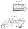
- This invention relates to an ink ribbon for sublimation transfer type hard copy, in which such ink ribbon containing a dye and a printing paper are in contact with each other and a picture image is formed on said printing paper by a selective heat treatment, which is characterized in that said ink ribbon includes a plastic film of polyethylene terephthalate substantially free of water content, an ink layer formed on the surface of said plastic film, said ink layer comprising a dye sublimable upon heating, a heat-resistant treating layer formed on another surface of said plastic film, and a lubricating layer on said heat-resistant treating layer.
- Fig. 2 shows an embodiment of this invention comprising a plastic film base 16 with a plastic film 14 of polyethylene terephthalate substantially free of water content, on the surface of which is formed a heat-resistant treating layer 15 which does not have a melting point and, on the surface of the plastic film on which the heat-resistant treating layer 15 is not formed, there is formed a sublimation dye coating layer 13.
- a lubricant layer 35 is formed on the heat-resistant treating layer 15 of the ink ribbon 11. This lubricant layer ensures that the ink ribbon can slide on the thermal print head smoothly.
- This lubricant layer can be formed by coating on the layer a releasing agent such a silicone resin.
- the heat-resistant treating layer 15 made of a substance which does not have a melting point is formed such that a resin such as nitrocellulose and polyimide lacquer which begin to be carbonized or decomposed before being melted by heat or a heat curable heat-resistant resin such as melamine resin, aminoalkyd resin, epoxy resin, silicone denatured epoxy resin or unsaturared polyester and unsaturated oligomer such as epoxy acrylate is mixed with a curing agent, coated and then cured.
- the heat-resistant treating layer may be made of coating layer containing a denatured silicone resin denatured by a resin such as alkyd resin, epoxy resin, acrylic resin or urethane resin.
- the denatured silicone resin is mixed with melamine resin or imidasol, coated and then cured to thereby form the heat-resistant treating layer.
- the thickness of the treating layer 15 is not limited particularly,but preferably selected in a range from 1 ⁇ m to 10 ⁇ m.
- a coating material in which a heat-resistant powder is dispersed into the resin available for forming the heat-resistant treating layer may be used to form the heat-resistant treating layer 15 of this ink ribbon 11.
- the heat-resistant powder may be inorganic powder such as silica, calcium carbonate, titanium oxide, carbon or graphite, heat-resistant organic powder such as teflon, silicone or cellulose powder.
- the heat-resistant treating layer 15 contains the heat-resistant powder, the friction coefficient between the ink ribbon 11 and the thermal print head can be lowered to thereby enable the ink ribbon to smoothly slide on the thermal print head.
- the heat-resistant treating layer 15 is formed on the surface of the plastic film, if the ink ribbon is exposed in a high temperature of about 400°C for a long time, the treating layer 15 and the plastic film 14 are both melted. However, the heating by the thermal print head lasts for a very short time of period ranging from several tens microseconds to several tens milliseconds so that the plastic film 14 is not melted and thus the heat-resistant property of the treating layer 15 can prevent the ink ribbon 11 from being melt bonded and deformed.
- the plastic film base of the ink ribbon for sublimation transfer type hard copy As described above, as the plastic film base of the ink ribbon for sublimation transfer type hard copy, the plastic film base having formed thereon the heat-resistant treating layer is used so that such film base contains no water component, thus the picture image becomes free of the bubble spot completely. Further, contrary to the condenser paper, the plastic film is swollen a little by the heating so that the ink ribbon in contact with the printing paper is not wrinkled. Accordingly, it is possible to increase the quality of the transferred picture image considerably.
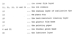
- Fig. 3 illustrates another embodiment of the present invention which utilizes the fundamental structure of the above-described present invention.
- the present invention is applied to an ink ribbon for a color picture image in which after the picture image is formed, the protecting layer can be formed successively.
- the coating layers 13 mainly made of the sublimation dye are formed sequentially as in the order of yellow Y, magenta M, cyan C and black B (this can be provided as required). Between the adjacent combinations of the ink layers 13 (Y, M, C and B) of 4 colors, there is formed a protecting layer or a cover film layer 10 to thereby form an ink ribbon 31 for a color picture image.
- This cover film layer 10 is made of a transparent resin layer which can not be bonded to the plastic film base 16 but can easily be melt bonded to the surface of the printing paper.
- the thickness of the cover film layer 10 is in a range from 1 to 10 ⁇ m.
- the material of this cover film layer may be polyester resin, epoxy resin, cellulose acetate resin, nylon resin or polyvinylpyrrolidone resin, each having a melt bonding property.
- the releasing treatment can be carried out between the base film 16 and the cover film layer 10.
- the cover film layer 10 may contain an ultraviolet absorbent or phosphor whitener, if necessary.
- Reference numeral 22 designates a sensor mark for use in determining the position.
- Fig. 4 illustrates a state of a transfer treatment which uses such an ink ribbon 31.
- Reference numeral 17 designates a printing paper in which a dye diffusing layer 19 is formed on the surface of a base 18.
- Reference numeral 23 designates a platen which moves the printing paper 17 and
- reference numeral 21 designates a thermal print head which is provided at its point with heat generating elements whose number is corresponding to the number of the picture elements in one scanning line of the picture image.
- the ink ribbon 31 is tightly pressed against the printing paper 17 by the thermal print head 21. In this ink ribbon 31, in like manner described in connection with Fig.
- each heat generating element of the thermal print head 21 is supplied with the electric power in accordance with the video signal so as to sequentially sublimate and transfer the dyes of yellow Y, magenta M, cyan C and black B in response to the heated amount, thus forming a color picture image on the printing paper 17.
- the ink ribbon 31 is heated at its portion of the cover film layer 10 by the thermal print head 21 to thereby melt bond the cover film layer 10 to the printing paper 17.
- a dye coagulated material 24 of picture image transferred from the ink ribbon 31 is diffused into the cover film layer 10 and the dye diffusing layer 19 of the printing paper 17.
- Reference numeral 25 designates the dye that is diffused as mentioned above.
- the cover film layer is formed.
- the heat-resistant plastic film base 16 so that the bubble spot caused by the evaporation of water component and the wrinkles will not appear and in addition, the protecting layer having the smooth surface can be formed.
- the releasing treatment may be carried out over the portion of the protecting layer and further, a primer treatment may be carried out over the portion in which each color coating layer is formed.
- An ink ribbon 32 for a black and white picture image is formed such that as shown in Fig. 5, the coating layer B of black color ink and the cover film layer 10 are sequentially formed.
- a base material 14 was made by a polyester film having a thickness of 8 ⁇ m. On one surface of this base material 14, there was coated a resin liquid having the following composition by a pipe coater such that the heat-resistant treating layer 15 might have a thickness of 3 ⁇ m after being dried. Thereafter, at a temperature of 130°C, it was heated and then cured for an hour.
- the heat-resistant treating layer 15 was made by the resin liquid having the above-described composition, on the surface opposing to the surface in contact with the thermal print head 4, there was coated a resin liquid having the following composition to thereby form the ink layer 13 of thermal transfer property, thus an ink ribbon for sublimation transfer recording being formed.
- the ink ribbon 11 for sublimation transfer recording which was formed in the above-described Reference Example was manufactured. Then, on the upper surface of the heat-resistant treating layer 15, there was coated a resin liquid having the following composition available for the purpose of lowering the friction coefficient upon transportation by using a gravure coater through a printing plate having a depth of 20 ⁇ m and 200 lines 2.54 cm (inch). This product was placed at a temperature of 130°C for 5 minutes and then cured to form the lubricant layer 35 (see Fig. 2), thus an ink ribbon for sublimation transfer recording of this example being produced.
- Fig. 6 illustrates a further embodiment of this invention.
- the coloring inherent to the dye can be developed and a coagulated material 24 of dye deposited on the printing paper 17 can be diffused well into the dye diffusing layer 19.
- the heat amount of the thermal print head 21 for such re-heating of the picture image is free from the restriction put by the signal that forms the picture image and becomes an electric power required by the whole of the resistor elements of the thermal print head 21 to diffuse the dye well.
- Such re-heating can be carried out a plurality of times by using the same portion 26 in which no coating layer is formed and this ensures that the dye can be fixed more completely. Further, as shown in Fig.
- the thin film 27 which is hard to be diffused with the dye can be obtained by coating casein, coating and curing a curable heat-resistant resin such as polyimide resin, silicone resin or melamine resin, metal plating, and metal thin film treatment.
- the picture image can be fixed without using the protecting layer. Since the protecting layer is not used, the printing paper can be protected from the deformation such as curl.
- Fig. 8 illustrates an embodiment in which the above-described structure is applied to an ink ribbon 34 for a black and white picture image.
- the black color coating layer B next to the black color coating layer B, there is formed the portion 26 having no coating layer.
- the film base of the ink ribbon for sublimation transfer type hard copy there is used a plastic film of polyethylene terephthalate having formed thereon a heat-resistant treating layer and a lubricating layer. Consequently, such film base contains no water component and produces no bubble unlike the prior art so that the bubble spot is removed from the picture image completely. Further, unlike the prior art condenser paper, the film base can be prevented from being shrunk largely by the heating and the film base is rather swollen a little so that no wrinkle is produced between the film base and the printing paper. Thus, the quality of the transferred picture image can be improved.
Claims (8)
- Tintenband für Papier vom Sublimationsübertragungstyp, wobei ein solches einen Farbstoff enthaltendes Tintenband und ein Druckpapier miteinander in Berührung stehen und auf dem Druckpapier durch eine selektive Wärmebehandlung ein Bild erzeugt wird, dadurch gekennzeich net, daß das Tintenband eine im wesentlichen wasserfreie Kunststoffolie aus Polyethylenterephthalat, eine auf der Oberfläche der Kunststoffolie gebildete Tintenschicht, wobei die Tintenschicht einen durch Erwärmung sublimierbaren Farbstoff umfaßt, eine auf einer anderen Oberfläche der Kunststoffolie gebildete wärmebeständige Behandlungsschicht und eine Gleitmittelschicht auf der wärmebeständigen Behandlungsschicht beinhaltet.
- Tintenband für Papier vom Sublimationsübertragungstyp nach Anspruch 1, dadurch gekennzeichnet, daß eine aus einer transparenten Harzschicht hergestellte Deckfolienschicht, welche auf ein bedrucktes Druckpapier schmelzgebunden und zu übertragen ist, weiterhin auf der Foliengrundlage ausgebildet ist.
- Tintenband für Papier vom Sublimationsübertragungstyp nach Anspruch 1, dadurch gekennzeichnet, daß Beschichtungsbereiche aus Gelb-, Magenta- und Blaugrün-Farbstoffen auf der Kunststoffolie der Reihe nach in Längsrichtung der Folie ausgebildet sind.
- Tintenband für Papier vom Sublimationsübertragungstyp nach Anspruch 3, dadurch gekennzeichnet, daß Farbstoffbeschichtungsbereiche aus gelb, magenta, blaugrün und schwarz auf der Folie der Reihe nach in Längsrichtung der Folie ausgebildet sind.
- Tintenband für Papier vom Sublimationsübertragungstyp nach Anspruch 3, dadurch gekennzeichnet, daß Farbstoffbeschichtungsbereiche aus gelb, magenta und blaugrün und ein Deckfolienbereich auf der Folie der Reihe nach in Längsrichtung der Folie ausgebildet sind.
- Tintenband für Papier vom sublimationsübertragungstyp nach Anspruch 3, dadurch gekennzeichnet, daß Farbstoffbeschichtungsbereiche aus gelb, magenta, blaugrün und schwarz sowie ein Deckfolienbereich auf der Folie der Reihe nach in Längsrichtung der Folie ausgebildet sind.
- Tintenband für Papier vom Sublimationsübertragungstyp nach Anspruch 1, dadurch gekennzeichnet, daß die wärmebeständige Behandlungsschicht aus einem Harz hergestellt ist, welches keinen Schmelzpunkt besitzt.
- Tintenband für Papier vom sublimationsübertragungstyp nach Anspruch 7, dadurch gekennzeichnet, daß die wärmebeständige Behandlungsschicht durch Härten eines denaturierten Silikonharzes, welches durch ein aus Alkydharz, Urethanharz, Epoxyharz oderAcrylharz gewähltes Harz denaturiert ist, gebildet ist.
Applications Claiming Priority (4)
| Application Number | Priority Date | Filing Date | Title |
|---|---|---|---|
| JP58192959A JPH0632974B2 (ja) | 1983-10-15 | 1983-10-15 | 昇華転写式ハードコピー用インクリボン |
| JP192959/83 | 1983-10-15 | ||
| JP82251/84 | 1984-04-24 | ||
| JP59082251A JPS60225777A (ja) | 1984-04-24 | 1984-04-24 | 感熱転写記録用インクリボン |
Related Parent Applications (3)
| Application Number | Title | Priority Date | Filing Date |
|---|---|---|---|
| EP84903765.0 Division | 1984-10-15 | ||
| EP84903765A Division-Into EP0160098B1 (de) | 1983-10-15 | 1984-10-15 | Tintenband für sublimierungsübertragung auf papier |
| EP84903765A Division EP0160098B1 (de) | 1983-10-15 | 1984-10-15 | Tintenband für sublimierungsübertragung auf papier |
Publications (2)
| Publication Number | Publication Date |
|---|---|
| EP0401878A1 EP0401878A1 (de) | 1990-12-12 |
| EP0401878B1 true EP0401878B1 (de) | 1994-01-26 |
Family
ID=26423269
Family Applications (2)
| Application Number | Title | Priority Date | Filing Date |
|---|---|---|---|
| EP90114883A Expired - Lifetime EP0401878B1 (de) | 1983-10-15 | 1984-10-15 | Tintenband für Sublimierungsübertragung auf Papier |
| EP84903765A Expired EP0160098B1 (de) | 1983-10-15 | 1984-10-15 | Tintenband für sublimierungsübertragung auf papier |
Family Applications After (1)
| Application Number | Title | Priority Date | Filing Date |
|---|---|---|---|
| EP84903765A Expired EP0160098B1 (de) | 1983-10-15 | 1984-10-15 | Tintenband für sublimierungsübertragung auf papier |
Country Status (4)
| Country | Link |
|---|---|
| US (1) | US4666320A (de) |
| EP (2) | EP0401878B1 (de) |
| DE (2) | DE3486270T2 (de) |
| WO (1) | WO1985001698A1 (de) |
Families Citing this family (46)
| Publication number | Priority date | Publication date | Assignee | Title |
|---|---|---|---|---|
| JPS62202786A (ja) * | 1986-03-04 | 1987-09-07 | Dainichi Color & Chem Mfg Co Ltd | 感熱記録材料 |
| JP2533520B2 (ja) * | 1986-03-18 | 1996-09-11 | 大日本印刷株式会社 | 感熱転写リボン |
| DE3769889D1 (de) * | 1986-08-27 | 1991-06-13 | Hitachi Ltd | Waermetransferverfahren und waermetransferfarbbogen fuer die verwendung in diesem verfahren. |
| JPS6356692U (de) * | 1986-09-30 | 1988-04-15 | ||
| JPS6356693U (de) * | 1986-09-30 | 1988-04-15 | ||
| US4925324A (en) * | 1987-10-02 | 1990-05-15 | Alps Electric Co., Ltd. | Color ink ribbon for thermal printer |
| JP2504507B2 (ja) * | 1988-02-17 | 1996-06-05 | 三菱化学株式会社 | 熱転写記録用シ―ト |
| US5087137A (en) * | 1988-07-19 | 1992-02-11 | Datamax Corporation | Ribbon assembly including indicia to identify operating parameters and ribbon depletion |
| US6186207B1 (en) | 1988-09-06 | 2001-02-13 | Donald C. Berghauser | Press for transferring video prints to ceramic mugs and other surfaces |
| CA1335329C (en) * | 1988-09-06 | 1995-04-25 | Donald C. Berghauser | Color sublimation dye transfer from color video prints to ceramic mugs and the like |
| US5244234A (en) * | 1988-09-12 | 1993-09-14 | Dai Nippon Insatsu Kabushiki Kaisha | Image receiving medium |
| GB8826455D0 (en) * | 1988-11-11 | 1988-12-14 | Ici Plc | Dyesheet |
| US5179391A (en) * | 1989-03-03 | 1993-01-12 | Fuji Photo Film Co., Ltd. | Thermal printer and thermal printing method |
| JPH02249657A (ja) * | 1989-03-24 | 1990-10-05 | Fuji Photo Film Co Ltd | ビデオプリンタおよびその後処理方法 |
| US5302223A (en) * | 1990-07-09 | 1994-04-12 | Sawgrass Systems, Inc. | Permanent heat sensitive transfer printing process |
| US5575877A (en) * | 1990-07-09 | 1996-11-19 | Sawgrass Systems, Inc. | Printing method of applying a polymer surface preparation material to a substrate |
| US5493409A (en) * | 1990-11-29 | 1996-02-20 | Minolta Camera Kabushiki Kaisha | Still video camera having a printer capable of printing a photographed image in a plurality of printing modes |
| JP3049792B2 (ja) * | 1991-02-27 | 2000-06-05 | 三菱化学株式会社 | 熱転写記録用シート |
| US5921687A (en) * | 1991-05-24 | 1999-07-13 | Mitsubishi Denki Kabushiki Kaisha | Printing apparatus |
| US5474394A (en) * | 1991-05-24 | 1995-12-12 | Mitsubishi Denki Kabushiki Kaisha | Printing apparatus |
| DE69218313T2 (de) * | 1991-07-17 | 1997-10-23 | Sony Corp | Farbstoffenthaltende Schicht für Thermoübertragungsdruck |
| DE69221602T2 (de) * | 1992-01-28 | 1998-02-26 | Agfa Gevaert Nv | Farbstoffgebendes Element für thermische Farbstoffübertragung durch Sublimation |
| US5547739A (en) * | 1992-07-14 | 1996-08-20 | Sony Corporation | Recording medium for heat sensitive transfer printing |
| US5266970A (en) * | 1992-08-05 | 1993-11-30 | Eastman Kodak Company | Hot bar fuser |
| JPH0699671A (ja) * | 1992-09-22 | 1994-04-12 | Sony Corp | 感熱転写記録材料 |
| US5445463A (en) * | 1993-03-30 | 1995-08-29 | Paranjpe; Suresh C. | Combination ink or dye ribbon for nonimpact printing |
| US5698490A (en) * | 1993-07-22 | 1997-12-16 | Sony Corporation | Thermal transfer ink ribbons using the same |
| US5656759A (en) * | 1993-07-22 | 1997-08-12 | Sony Corporation | Hydrophobic cationic dye compounds |
| US5387573A (en) * | 1993-12-07 | 1995-02-07 | Eastman Kodak Company | Thermal dye transfer dye-donor element with transferable protection overcoat containing particles |
| US5332713A (en) * | 1993-12-07 | 1994-07-26 | Eastman Kodak Company | Thermal dye transfer dye-donor element containing transferable protection overcoat |
| JPH07237362A (ja) * | 1994-02-28 | 1995-09-12 | Brother Ind Ltd | テープユニット |
| JPH07237307A (ja) * | 1994-02-28 | 1995-09-12 | Shinko Electric Co Ltd | 昇華式熱転写プリンタ |
| DE69405975T2 (de) * | 1994-04-29 | 1998-04-09 | Agfa Gevaert Nv | Drucksachenherstellungsverfahren mittels eines thermo-druckers |
| JPH111064A (ja) * | 1996-11-07 | 1999-01-06 | Ricoh Co Ltd | 昇華型熱転写記録方法及び昇華転写用受像シート |
| DE69802022T2 (de) * | 1997-01-29 | 2002-03-14 | Alps Electric Co Ltd | Wärmübertragungsdrucker |
| JP2002205453A (ja) * | 2001-01-11 | 2002-07-23 | Seiko Epson Corp | 偽造防止用の画像形成方法および画像形成装置 |
| JP5151496B2 (ja) * | 2008-01-17 | 2013-02-27 | ソニー株式会社 | 画像形成装置及びそれに用いる改質シートカートリッジ |
| JP5169407B2 (ja) * | 2008-04-10 | 2013-03-27 | ソニー株式会社 | 画像形成装置、表面性改質シートおよび画像形成方法 |
| US9141157B2 (en) * | 2011-10-13 | 2015-09-22 | Texas Instruments Incorporated | Molded power supply system having a thermally insulated component |
| CN103085510B (zh) * | 2013-02-08 | 2014-12-17 | 国家电网公司 | 一种用于线缆护套表面的环保型印字色带 |
| CN104476932B (zh) * | 2013-02-08 | 2016-11-30 | 国网山东省电力公司菏泽供电公司 | 用于线缆护套表面的环保型印字色带 |
| CN104476931B (zh) * | 2013-02-08 | 2017-02-08 | 国网山东省电力公司蒙阴县供电公司 | 环保型用于线缆护套表面的印字色带 |
| CN104527240B (zh) * | 2013-02-08 | 2016-09-14 | 国家电网公司 | 用于线缆护套表面的印字色带 |
| TWI560077B (en) * | 2013-10-30 | 2016-12-01 | Hiti Digital Inc | Sublimation printer |
| CN104924794A (zh) | 2014-03-17 | 2015-09-23 | 诚研科技股份有限公司 | 热升华透明介质列印方法及其制品 |
| EP3351394B1 (de) * | 2015-09-18 | 2020-10-21 | Dai Nippon Printing Co., Ltd. | Bild- und schutzschichtformungsverfahren und -vorrichtung |
Family Cites Families (18)
| Publication number | Priority date | Publication date | Assignee | Title |
|---|---|---|---|---|
| US3596055A (en) * | 1969-05-08 | 1971-07-27 | Texas Instruments Inc | Method and apparatus for producing displays utilizing an electronic display system |
| JPS5284296A (en) * | 1976-01-01 | 1977-07-13 | Riken Keikinzoku Kogyo Kk | Denatured silicone and its producing method |
| US4309117A (en) * | 1979-12-26 | 1982-01-05 | International Business Machines Corporation | Ribbon configuration for resistive ribbon thermal transfer printing |
| JPS5698190A (en) * | 1980-01-07 | 1981-08-07 | Fuji Kagakushi Kogyo Co Ltd | Ribbon for color thermotranscription |
| JPS56105994A (en) * | 1980-01-28 | 1981-08-22 | Canon Inc | Ink carrier for heat transcription |
| US4269892A (en) * | 1980-02-04 | 1981-05-26 | International Business Machines Corporation | Polyester ribbon for non-impact printing |
| JPS5743889A (en) * | 1980-08-29 | 1982-03-12 | Fuji Xerox Co Ltd | Heat transfer recording medium |
| US4427985A (en) * | 1980-08-29 | 1984-01-24 | Fuji Xerox Co., Ltd. | Thermorecording medium, means and process for producing and utilizing same |
| DE3218732A1 (de) * | 1981-05-20 | 1982-12-09 | Ricoh Co., Ltd., Tokyo | Farbband fuer die elektrothermische schlaglose aufzeichnung |
| JPS57189883A (en) * | 1981-05-20 | 1982-11-22 | Ricoh Co Ltd | Heat-sensitive diazo recording material |
| JPS57201686A (en) * | 1981-06-05 | 1982-12-10 | Sony Corp | Color printer |
| JPS5824477A (ja) * | 1981-08-06 | 1983-02-14 | Canon Inc | インクリボン |
| IT1145104B (it) * | 1981-09-21 | 1986-11-05 | Olivetti & Co Spa | Elemento inchiostrato termosensibile per stampanti senza impatto di tipo termico |
| JPS58138685A (ja) * | 1982-02-13 | 1983-08-17 | Fuji Kagakushi Kogyo Co Ltd | カラ−熱転写用記録媒体 |
| JPS58188690A (ja) * | 1982-04-30 | 1983-11-04 | Nippon Telegr & Teleph Corp <Ntt> | 多数回カラ−熱転写用リボン |
| US4453839A (en) * | 1982-06-15 | 1984-06-12 | International Business Machines Corporation | Laminated thermal transfer medium for lift-off correction and embodiment with resistive layer composition including lubricating contact graphite coating |
| JPS5995194A (ja) * | 1982-11-22 | 1984-06-01 | Victor Co Of Japan Ltd | 感熱転写印刷法 |
| JPS59138494A (ja) * | 1983-01-28 | 1984-08-08 | General Kk | 感熱転写材及びその製造方法 |
-
1984
- 1984-10-15 EP EP90114883A patent/EP0401878B1/de not_active Expired - Lifetime
- 1984-10-15 EP EP84903765A patent/EP0160098B1/de not_active Expired
- 1984-10-15 DE DE3486270T patent/DE3486270T2/de not_active Expired - Lifetime
- 1984-10-15 US US06/749,624 patent/US4666320A/en not_active Expired - Lifetime
- 1984-10-15 DE DE8484903765T patent/DE3484798D1/de not_active Expired - Lifetime
- 1984-10-15 WO PCT/JP1984/000488 patent/WO1985001698A1/ja active IP Right Grant
Also Published As
| Publication number | Publication date |
|---|---|
| EP0160098B1 (de) | 1991-07-10 |
| DE3486270D1 (de) | 1994-03-10 |
| EP0160098A4 (de) | 1987-12-09 |
| DE3484798D1 (de) | 1991-08-14 |
| US4666320A (en) | 1987-05-19 |
| EP0401878A1 (de) | 1990-12-12 |
| EP0160098A1 (de) | 1985-11-06 |
| WO1985001698A1 (en) | 1985-04-25 |
| DE3486270T2 (de) | 1994-09-01 |
Similar Documents
| Publication | Publication Date | Title |
|---|---|---|
| EP0401878B1 (de) | Tintenband für Sublimierungsübertragung auf Papier | |
| USRE37726E1 (en) | Method for transferring hot melt ink to a recording medium | |
| JPS59224392A (ja) | 感熱転写材 | |
| EP0721848B1 (de) | Verfahren zur bildübertragung | |
| JPS60225777A (ja) | 感熱転写記録用インクリボン | |
| US4518645A (en) | Transfer type heat sensitive recording medium | |
| EP0409598B1 (de) | Thermische Farbbildübertragungsempfangsschicht | |
| EP0389635B1 (de) | Wärmeübertragungsverfahren und -blatt | |
| JPS62297184A (ja) | 昇華転写式インクリボン | |
| EP0148276B1 (de) | Druckvorrichtung | |
| JPH0632974B2 (ja) | 昇華転写式ハードコピー用インクリボン | |
| JPS62214990A (ja) | 熱昇華プリントの退色防止方法 | |
| JPH0752552A (ja) | 熱染料転写画像用質量転写ドナーリボン | |
| KR20000000656A (ko) | 열전사 필름 | |
| US5300351A (en) | Heat-sensitive hot-melt image transfer sheet | |
| RU2146200C1 (ru) | Способ лазерной маркировки | |
| EP0117407A2 (de) | Wärmeübertragungsdruckverfahren | |
| WO2003000501A1 (fr) | Feuille de transfert thermique | |
| JPS6369691A (ja) | 金属光沢感熱転写記録体及びそれを使用した感熱転写記録方法 | |
| JPS63176186A (ja) | 感熱転写紙 | |
| JPH0229388A (ja) | 昇華型転写記録用転写体 | |
| JP2003266957A (ja) | 熱転写記録方法、熱転写記録媒体、および画像印画体 | |
| JPH0566273B2 (de) | ||
| JPH04347691A (ja) | カラー記録媒体および記録方法 | |
| JPS62128791A (ja) | 感熱転写シ−トおよびその使用方法 |
Legal Events
| Date | Code | Title | Description |
|---|---|---|---|
| PUAI | Public reference made under article 153(3) epc to a published international application that has entered the european phase |
Free format text: ORIGINAL CODE: 0009012 |
|
| AC | Divisional application: reference to earlier application |
Ref document number: 160098 Country of ref document: EP |
|
| AK | Designated contracting states |
Kind code of ref document: A1 Designated state(s): DE FR GB NL |
|
| 17P | Request for examination filed |
Effective date: 19901220 |
|
| 17Q | First examination report despatched |
Effective date: 19921014 |
|
| GRAA | (expected) grant |
Free format text: ORIGINAL CODE: 0009210 |
|
| AC | Divisional application: reference to earlier application |
Ref document number: 160098 Country of ref document: EP |
|
| AK | Designated contracting states |
Kind code of ref document: B1 Designated state(s): DE FR GB NL |
|
| REF | Corresponds to: |
Ref document number: 3486270 Country of ref document: DE Date of ref document: 19940310 |
|
| ET | Fr: translation filed | ||
| PLBE | No opposition filed within time limit |
Free format text: ORIGINAL CODE: 0009261 |
|
| STAA | Information on the status of an ep patent application or granted ep patent |
Free format text: STATUS: NO OPPOSITION FILED WITHIN TIME LIMIT |
|
| 26N | No opposition filed | ||
| REG | Reference to a national code |
Ref country code: GB Ref legal event code: IF02 |
|
| PGFP | Annual fee paid to national office [announced via postgrant information from national office to epo] |
Ref country code: FR Payment date: 20031003 Year of fee payment: 20 |
|
| PGFP | Annual fee paid to national office [announced via postgrant information from national office to epo] |
Ref country code: NL Payment date: 20031008 Year of fee payment: 20 |
|
| PGFP | Annual fee paid to national office [announced via postgrant information from national office to epo] |
Ref country code: GB Payment date: 20031016 Year of fee payment: 20 |
|
| PGFP | Annual fee paid to national office [announced via postgrant information from national office to epo] |
Ref country code: DE Payment date: 20031023 Year of fee payment: 20 |
|
| PG25 | Lapsed in a contracting state [announced via postgrant information from national office to epo] |
Ref country code: GB Free format text: LAPSE BECAUSE OF EXPIRATION OF PROTECTION Effective date: 20041014 |
|
| PG25 | Lapsed in a contracting state [announced via postgrant information from national office to epo] |
Ref country code: NL Free format text: LAPSE BECAUSE OF EXPIRATION OF PROTECTION Effective date: 20041015 |
|
| REG | Reference to a national code |
Ref country code: GB Ref legal event code: PE20 |
|
| NLV7 | Nl: ceased due to reaching the maximum lifetime of a patent |
Effective date: 20041015 |