EP0401835B1 - Matériel magnétique - Google Patents
Matériel magnétique Download PDFInfo
- Publication number
- EP0401835B1 EP0401835B1 EP19900110828 EP90110828A EP0401835B1 EP 0401835 B1 EP0401835 B1 EP 0401835B1 EP 19900110828 EP19900110828 EP 19900110828 EP 90110828 A EP90110828 A EP 90110828A EP 0401835 B1 EP0401835 B1 EP 0401835B1
- Authority
- EP
- European Patent Office
- Prior art keywords
- grains
- magnetic
- substance
- magnetic material
- coating film
- Prior art date
- Legal status (The legal status is an assumption and is not a legal conclusion. Google has not performed a legal analysis and makes no representation as to the accuracy of the status listed.)
- Expired - Lifetime
Links
- 239000000696 magnetic material Substances 0.000 title claims description 72
- 239000000126 substance Substances 0.000 claims description 67
- 229910045601 alloy Inorganic materials 0.000 claims description 52
- 239000000956 alloy Substances 0.000 claims description 52
- 238000000034 method Methods 0.000 claims description 40
- 239000011248 coating agent Substances 0.000 claims description 31
- 238000000576 coating method Methods 0.000 claims description 31
- 230000008569 process Effects 0.000 claims description 26
- XEEYBQQBJWHFJM-UHFFFAOYSA-N iron Substances [Fe] XEEYBQQBJWHFJM-UHFFFAOYSA-N 0.000 claims description 15
- 230000005415 magnetization Effects 0.000 claims description 13
- 239000007789 gas Substances 0.000 claims description 12
- 238000007731 hot pressing Methods 0.000 claims description 12
- 239000002245 particle Substances 0.000 claims description 10
- 230000015572 biosynthetic process Effects 0.000 claims description 8
- IJGRMHOSHXDMSA-UHFFFAOYSA-N Atomic nitrogen Chemical compound N#N IJGRMHOSHXDMSA-UHFFFAOYSA-N 0.000 claims description 6
- 229910017052 cobalt Inorganic materials 0.000 claims description 6
- 239000010941 cobalt Substances 0.000 claims description 6
- GUTLYIVDDKVIGB-UHFFFAOYSA-N cobalt atom Chemical compound [Co] GUTLYIVDDKVIGB-UHFFFAOYSA-N 0.000 claims description 6
- 238000010438 heat treatment Methods 0.000 claims description 6
- MYMOFIZGZYHOMD-UHFFFAOYSA-N Dioxygen Chemical compound O=O MYMOFIZGZYHOMD-UHFFFAOYSA-N 0.000 claims description 5
- 229910001882 dioxygen Inorganic materials 0.000 claims description 5
- 238000004544 sputter deposition Methods 0.000 claims description 5
- 229910001873 dinitrogen Inorganic materials 0.000 claims description 4
- 229910052742 iron Inorganic materials 0.000 claims description 4
- 229910052782 aluminium Inorganic materials 0.000 claims description 3
- 230000005381 magnetic domain Effects 0.000 claims description 3
- 229910044991 metal oxide Inorganic materials 0.000 claims description 3
- 150000004706 metal oxides Chemical class 0.000 claims description 3
- 238000005551 mechanical alloying Methods 0.000 claims description 2
- 229910052759 nickel Inorganic materials 0.000 claims description 2
- 229910052710 silicon Inorganic materials 0.000 claims description 2
- 150000004767 nitrides Chemical class 0.000 claims 2
- 239000000843 powder Substances 0.000 description 72
- 239000002131 composite material Substances 0.000 description 41
- 229910052751 metal Inorganic materials 0.000 description 37
- 239000002184 metal Substances 0.000 description 37
- 239000010408 film Substances 0.000 description 33
- 239000008187 granular material Substances 0.000 description 19
- VYPSYNLAJGMNEJ-UHFFFAOYSA-N Silicium dioxide Chemical compound O=[Si]=O VYPSYNLAJGMNEJ-UHFFFAOYSA-N 0.000 description 17
- 230000004907 flux Effects 0.000 description 17
- 230000035699 permeability Effects 0.000 description 17
- 150000002739 metals Chemical class 0.000 description 14
- 229910003271 Ni-Fe Inorganic materials 0.000 description 12
- 239000011162 core material Substances 0.000 description 11
- 239000000463 material Substances 0.000 description 11
- 239000000203 mixture Substances 0.000 description 11
- 238000000465 moulding Methods 0.000 description 11
- 238000007906 compression Methods 0.000 description 10
- 239000002002 slurry Substances 0.000 description 10
- 230000006835 compression Effects 0.000 description 9
- 230000003647 oxidation Effects 0.000 description 9
- 238000007254 oxidation reaction Methods 0.000 description 9
- 239000011230 binding agent Substances 0.000 description 8
- 239000000377 silicon dioxide Substances 0.000 description 8
- 229960001866 silicon dioxide Drugs 0.000 description 8
- 235000012239 silicon dioxide Nutrition 0.000 description 8
- 229910008389 Si—Al—Fe Inorganic materials 0.000 description 7
- 239000012298 atmosphere Substances 0.000 description 7
- 238000000280 densification Methods 0.000 description 7
- 229910000859 α-Fe Inorganic materials 0.000 description 7
- LYCAIKOWRPUZTN-UHFFFAOYSA-N Ethylene glycol Chemical compound OCCO LYCAIKOWRPUZTN-UHFFFAOYSA-N 0.000 description 6
- 238000003825 pressing Methods 0.000 description 6
- 229920006395 saturated elastomer Polymers 0.000 description 6
- 239000012212 insulator Substances 0.000 description 5
- XKRFYHLGVUSROY-UHFFFAOYSA-N Argon Chemical compound [Ar] XKRFYHLGVUSROY-UHFFFAOYSA-N 0.000 description 4
- 229910000531 Co alloy Inorganic materials 0.000 description 4
- PEDCQBHIVMGVHV-UHFFFAOYSA-N Glycerine Chemical compound OCC(O)CO PEDCQBHIVMGVHV-UHFFFAOYSA-N 0.000 description 4
- TWNQGVIAIRXVLR-UHFFFAOYSA-N oxo(oxoalumanyloxy)alumane Chemical compound O=[Al]O[Al]=O TWNQGVIAIRXVLR-UHFFFAOYSA-N 0.000 description 4
- 239000010409 thin film Substances 0.000 description 4
- 229910000967 As alloy Inorganic materials 0.000 description 3
- PXHVJJICTQNCMI-UHFFFAOYSA-N Nickel Chemical compound [Ni] PXHVJJICTQNCMI-UHFFFAOYSA-N 0.000 description 3
- -1 for example Substances 0.000 description 3
- 230000001788 irregular Effects 0.000 description 3
- 239000006247 magnetic powder Substances 0.000 description 3
- 238000004519 manufacturing process Methods 0.000 description 3
- 230000001590 oxidative effect Effects 0.000 description 3
- 238000000682 scanning probe acoustic microscopy Methods 0.000 description 3
- 238000005245 sintering Methods 0.000 description 3
- 229910000640 Fe alloy Inorganic materials 0.000 description 2
- 229910001030 Iron–nickel alloy Inorganic materials 0.000 description 2
- 238000005481 NMR spectroscopy Methods 0.000 description 2
- 229910008421 Si—Al—Ni Inorganic materials 0.000 description 2
- QVYYOKWPCQYKEY-UHFFFAOYSA-N [Fe].[Co] Chemical compound [Fe].[Co] QVYYOKWPCQYKEY-UHFFFAOYSA-N 0.000 description 2
- 229910052786 argon Inorganic materials 0.000 description 2
- 230000000052 comparative effect Effects 0.000 description 2
- 238000000748 compression moulding Methods 0.000 description 2
- 239000000470 constituent Substances 0.000 description 2
- 230000007812 deficiency Effects 0.000 description 2
- 235000011187 glycerol Nutrition 0.000 description 2
- 238000007373 indentation Methods 0.000 description 2
- 230000006698 induction Effects 0.000 description 2
- 239000011261 inert gas Substances 0.000 description 2
- 239000002648 laminated material Substances 0.000 description 2
- 238000003754 machining Methods 0.000 description 2
- 229910001004 magnetic alloy Inorganic materials 0.000 description 2
- 238000005259 measurement Methods 0.000 description 2
- 239000002609 medium Substances 0.000 description 2
- 238000002156 mixing Methods 0.000 description 2
- 239000012299 nitrogen atmosphere Substances 0.000 description 2
- 229910000889 permalloy Inorganic materials 0.000 description 2
- 239000004033 plastic Substances 0.000 description 2
- 239000011148 porous material Substances 0.000 description 2
- 239000002994 raw material Substances 0.000 description 2
- 238000004626 scanning electron microscopy Methods 0.000 description 2
- 229910000838 Al alloy Inorganic materials 0.000 description 1
- 229910018125 Al-Si Inorganic materials 0.000 description 1
- 229910018520 Al—Si Inorganic materials 0.000 description 1
- 229910017061 Fe Co Inorganic materials 0.000 description 1
- 229910017082 Fe-Si Inorganic materials 0.000 description 1
- 229910017133 Fe—Si Inorganic materials 0.000 description 1
- 229910001289 Manganese-zinc ferrite Inorganic materials 0.000 description 1
- 229910000676 Si alloy Inorganic materials 0.000 description 1
- 229910002796 Si–Al Inorganic materials 0.000 description 1
- 241000656145 Thyrsites atun Species 0.000 description 1
- JIYIUPFAJUGHNL-UHFFFAOYSA-N [O--].[O--].[O--].[O--].[O--].[O--].[O--].[O--].[O--].[O--].[O--].[O--].[O--].[O--].[O--].[O--].[O--].[O--].[O--].[O--].[Mn++].[Mn++].[Mn++].[Fe+3].[Fe+3].[Fe+3].[Fe+3].[Fe+3].[Fe+3].[Fe+3].[Fe+3].[Fe+3].[Fe+3].[Zn++].[Zn++] Chemical compound [O--].[O--].[O--].[O--].[O--].[O--].[O--].[O--].[O--].[O--].[O--].[O--].[O--].[O--].[O--].[O--].[O--].[O--].[O--].[O--].[Mn++].[Mn++].[Mn++].[Fe+3].[Fe+3].[Fe+3].[Fe+3].[Fe+3].[Fe+3].[Fe+3].[Fe+3].[Fe+3].[Fe+3].[Zn++].[Zn++] JIYIUPFAJUGHNL-UHFFFAOYSA-N 0.000 description 1
- 238000005299 abrasion Methods 0.000 description 1
- 230000002411 adverse Effects 0.000 description 1
- 238000004458 analytical method Methods 0.000 description 1
- 239000011449 brick Substances 0.000 description 1
- 239000012159 carrier gas Substances 0.000 description 1
- 239000000919 ceramic Substances 0.000 description 1
- 239000007931 coated granule Substances 0.000 description 1
- 239000011365 complex material Substances 0.000 description 1
- 238000001816 cooling Methods 0.000 description 1
- PMHQVHHXPFUNSP-UHFFFAOYSA-M copper(1+);methylsulfanylmethane;bromide Chemical compound Br[Cu].CSC PMHQVHHXPFUNSP-UHFFFAOYSA-M 0.000 description 1
- 230000000875 corresponding effect Effects 0.000 description 1
- 238000005520 cutting process Methods 0.000 description 1
- 230000003247 decreasing effect Effects 0.000 description 1
- 230000005347 demagnetization Effects 0.000 description 1
- 238000000151 deposition Methods 0.000 description 1
- 230000008021 deposition Effects 0.000 description 1
- 229910003460 diamond Inorganic materials 0.000 description 1
- 239000010432 diamond Substances 0.000 description 1
- 239000002612 dispersion medium Substances 0.000 description 1
- 238000009826 distribution Methods 0.000 description 1
- 238000007606 doctor blade method Methods 0.000 description 1
- 239000003814 drug Substances 0.000 description 1
- 238000001035 drying Methods 0.000 description 1
- 238000003384 imaging method Methods 0.000 description 1
- 238000003475 lamination Methods 0.000 description 1
- 239000000395 magnesium oxide Substances 0.000 description 1
- CPLXHLVBOLITMK-UHFFFAOYSA-N magnesium oxide Inorganic materials [Mg]=O CPLXHLVBOLITMK-UHFFFAOYSA-N 0.000 description 1
- AXZKOIWUVFPNLO-UHFFFAOYSA-N magnesium;oxygen(2-) Chemical compound [O-2].[Mg+2] AXZKOIWUVFPNLO-UHFFFAOYSA-N 0.000 description 1
- WJZHMLNIAZSFDO-UHFFFAOYSA-N manganese zinc Chemical compound [Mn].[Zn] WJZHMLNIAZSFDO-UHFFFAOYSA-N 0.000 description 1
- 238000012986 modification Methods 0.000 description 1
- 230000004048 modification Effects 0.000 description 1
- 229910001172 neodymium magnet Inorganic materials 0.000 description 1
- QELJHCBNGDEXLD-UHFFFAOYSA-N nickel zinc Chemical compound [Ni].[Zn] QELJHCBNGDEXLD-UHFFFAOYSA-N 0.000 description 1
- 229910052757 nitrogen Inorganic materials 0.000 description 1
- 239000000615 nonconductor Substances 0.000 description 1
- 230000000149 penetrating effect Effects 0.000 description 1
- 238000005498 polishing Methods 0.000 description 1
- 238000002360 preparation method Methods 0.000 description 1
- 238000010298 pulverizing process Methods 0.000 description 1
- 229910052814 silicon oxide Inorganic materials 0.000 description 1
- 239000002904 solvent Substances 0.000 description 1
- 238000003756 stirring Methods 0.000 description 1
- 238000010301 surface-oxidation reaction Methods 0.000 description 1
- 239000011885 synergistic combination Substances 0.000 description 1
- 238000005979 thermal decomposition reaction Methods 0.000 description 1
- 229910006297 γ-Fe2O3 Inorganic materials 0.000 description 1
Images


Classifications
-
- G—PHYSICS
- G11—INFORMATION STORAGE
- G11B—INFORMATION STORAGE BASED ON RELATIVE MOVEMENT BETWEEN RECORD CARRIER AND TRANSDUCER
- G11B5/00—Recording by magnetisation or demagnetisation of a record carrier; Reproducing by magnetic means; Record carriers therefor
- G11B5/127—Structure or manufacture of heads, e.g. inductive
- G11B5/133—Structure or manufacture of heads, e.g. inductive with cores composed of particles, e.g. with dust cores, with ferrite cores with cores composed of isolated magnetic particles
-
- H—ELECTRICITY
- H01—ELECTRIC ELEMENTS
- H01F—MAGNETS; INDUCTANCES; TRANSFORMERS; SELECTION OF MATERIALS FOR THEIR MAGNETIC PROPERTIES
- H01F1/00—Magnets or magnetic bodies characterised by the magnetic materials therefor; Selection of materials for their magnetic properties
- H01F1/01—Magnets or magnetic bodies characterised by the magnetic materials therefor; Selection of materials for their magnetic properties of inorganic materials
- H01F1/03—Magnets or magnetic bodies characterised by the magnetic materials therefor; Selection of materials for their magnetic properties of inorganic materials characterised by their coercivity
- H01F1/032—Magnets or magnetic bodies characterised by the magnetic materials therefor; Selection of materials for their magnetic properties of inorganic materials characterised by their coercivity of hard-magnetic materials
- H01F1/09—Magnets or magnetic bodies characterised by the magnetic materials therefor; Selection of materials for their magnetic properties of inorganic materials characterised by their coercivity of hard-magnetic materials mixtures of metallic and non-metallic particles; metallic particles having oxide skin
-
- G—PHYSICS
- G11—INFORMATION STORAGE
- G11B—INFORMATION STORAGE BASED ON RELATIVE MOVEMENT BETWEEN RECORD CARRIER AND TRANSDUCER
- G11B5/00—Recording by magnetisation or demagnetisation of a record carrier; Reproducing by magnetic means; Record carriers therefor
- G11B5/127—Structure or manufacture of heads, e.g. inductive
- G11B5/187—Structure or manufacture of the surface of the head in physical contact with, or immediately adjacent to the recording medium; Pole pieces; Gap features
- G11B5/193—Structure or manufacture of the surface of the head in physical contact with, or immediately adjacent to the recording medium; Pole pieces; Gap features the pole pieces being ferrite or other magnetic particles
-
- H—ELECTRICITY
- H01—ELECTRIC ELEMENTS
- H01F—MAGNETS; INDUCTANCES; TRANSFORMERS; SELECTION OF MATERIALS FOR THEIR MAGNETIC PROPERTIES
- H01F1/00—Magnets or magnetic bodies characterised by the magnetic materials therefor; Selection of materials for their magnetic properties
- H01F1/01—Magnets or magnetic bodies characterised by the magnetic materials therefor; Selection of materials for their magnetic properties of inorganic materials
- H01F1/03—Magnets or magnetic bodies characterised by the magnetic materials therefor; Selection of materials for their magnetic properties of inorganic materials characterised by their coercivity
- H01F1/032—Magnets or magnetic bodies characterised by the magnetic materials therefor; Selection of materials for their magnetic properties of inorganic materials characterised by their coercivity of hard-magnetic materials
- H01F1/04—Magnets or magnetic bodies characterised by the magnetic materials therefor; Selection of materials for their magnetic properties of inorganic materials characterised by their coercivity of hard-magnetic materials metals or alloys
- H01F1/06—Magnets or magnetic bodies characterised by the magnetic materials therefor; Selection of materials for their magnetic properties of inorganic materials characterised by their coercivity of hard-magnetic materials metals or alloys in the form of particles, e.g. powder
- H01F1/08—Magnets or magnetic bodies characterised by the magnetic materials therefor; Selection of materials for their magnetic properties of inorganic materials characterised by their coercivity of hard-magnetic materials metals or alloys in the form of particles, e.g. powder pressed, sintered, or bound together
- H01F1/083—Magnets or magnetic bodies characterised by the magnetic materials therefor; Selection of materials for their magnetic properties of inorganic materials characterised by their coercivity of hard-magnetic materials metals or alloys in the form of particles, e.g. powder pressed, sintered, or bound together in a bonding agent
-
- H—ELECTRICITY
- H01—ELECTRIC ELEMENTS
- H01F—MAGNETS; INDUCTANCES; TRANSFORMERS; SELECTION OF MATERIALS FOR THEIR MAGNETIC PROPERTIES
- H01F1/00—Magnets or magnetic bodies characterised by the magnetic materials therefor; Selection of materials for their magnetic properties
- H01F1/01—Magnets or magnetic bodies characterised by the magnetic materials therefor; Selection of materials for their magnetic properties of inorganic materials
- H01F1/03—Magnets or magnetic bodies characterised by the magnetic materials therefor; Selection of materials for their magnetic properties of inorganic materials characterised by their coercivity
- H01F1/12—Magnets or magnetic bodies characterised by the magnetic materials therefor; Selection of materials for their magnetic properties of inorganic materials characterised by their coercivity of soft-magnetic materials
- H01F1/14—Magnets or magnetic bodies characterised by the magnetic materials therefor; Selection of materials for their magnetic properties of inorganic materials characterised by their coercivity of soft-magnetic materials metals or alloys
- H01F1/20—Magnets or magnetic bodies characterised by the magnetic materials therefor; Selection of materials for their magnetic properties of inorganic materials characterised by their coercivity of soft-magnetic materials metals or alloys in the form of particles, e.g. powder
- H01F1/22—Magnets or magnetic bodies characterised by the magnetic materials therefor; Selection of materials for their magnetic properties of inorganic materials characterised by their coercivity of soft-magnetic materials metals or alloys in the form of particles, e.g. powder pressed, sintered, or bound together
- H01F1/24—Magnets or magnetic bodies characterised by the magnetic materials therefor; Selection of materials for their magnetic properties of inorganic materials characterised by their coercivity of soft-magnetic materials metals or alloys in the form of particles, e.g. powder pressed, sintered, or bound together the particles being insulated
-
- Y—GENERAL TAGGING OF NEW TECHNOLOGICAL DEVELOPMENTS; GENERAL TAGGING OF CROSS-SECTIONAL TECHNOLOGIES SPANNING OVER SEVERAL SECTIONS OF THE IPC; TECHNICAL SUBJECTS COVERED BY FORMER USPC CROSS-REFERENCE ART COLLECTIONS [XRACs] AND DIGESTS
- Y10—TECHNICAL SUBJECTS COVERED BY FORMER USPC
- Y10S—TECHNICAL SUBJECTS COVERED BY FORMER USPC CROSS-REFERENCE ART COLLECTIONS [XRACs] AND DIGESTS
- Y10S428/00—Stock material or miscellaneous articles
- Y10S428/90—Magnetic feature
-
- Y—GENERAL TAGGING OF NEW TECHNOLOGICAL DEVELOPMENTS; GENERAL TAGGING OF CROSS-SECTIONAL TECHNOLOGIES SPANNING OVER SEVERAL SECTIONS OF THE IPC; TECHNICAL SUBJECTS COVERED BY FORMER USPC CROSS-REFERENCE ART COLLECTIONS [XRACs] AND DIGESTS
- Y10—TECHNICAL SUBJECTS COVERED BY FORMER USPC
- Y10T—TECHNICAL SUBJECTS COVERED BY FORMER US CLASSIFICATION
- Y10T428/00—Stock material or miscellaneous articles
- Y10T428/11—Magnetic recording head
- Y10T428/115—Magnetic layer composition
-
- Y—GENERAL TAGGING OF NEW TECHNOLOGICAL DEVELOPMENTS; GENERAL TAGGING OF CROSS-SECTIONAL TECHNOLOGIES SPANNING OVER SEVERAL SECTIONS OF THE IPC; TECHNICAL SUBJECTS COVERED BY FORMER USPC CROSS-REFERENCE ART COLLECTIONS [XRACs] AND DIGESTS
- Y10—TECHNICAL SUBJECTS COVERED BY FORMER USPC
- Y10T—TECHNICAL SUBJECTS COVERED BY FORMER US CLASSIFICATION
- Y10T428/00—Stock material or miscellaneous articles
- Y10T428/249921—Web or sheet containing structurally defined element or component
- Y10T428/249953—Composite having voids in a component [e.g., porous, cellular, etc.]
- Y10T428/249955—Void-containing component partially impregnated with adjacent component
- Y10T428/249956—Void-containing component is inorganic
-
- Y—GENERAL TAGGING OF NEW TECHNOLOGICAL DEVELOPMENTS; GENERAL TAGGING OF CROSS-SECTIONAL TECHNOLOGIES SPANNING OVER SEVERAL SECTIONS OF THE IPC; TECHNICAL SUBJECTS COVERED BY FORMER USPC CROSS-REFERENCE ART COLLECTIONS [XRACs] AND DIGESTS
- Y10—TECHNICAL SUBJECTS COVERED BY FORMER USPC
- Y10T—TECHNICAL SUBJECTS COVERED BY FORMER US CLASSIFICATION
- Y10T428/00—Stock material or miscellaneous articles
- Y10T428/29—Coated or structually defined flake, particle, cell, strand, strand portion, rod, filament, macroscopic fiber or mass thereof
- Y10T428/2982—Particulate matter [e.g., sphere, flake, etc.]
- Y10T428/2991—Coated
Definitions
- the present invention relates to a magnetic material which is suitable for use in magnetic cores for electronic equipment such as transformer cores or magnetic heads, as well as permanent magnets.
- magnetic metals are used as magnetic materials for electronic components, electronic equipment and other products.
- magnetic metals cannot be used in the high frequency regions, and therefore, in place of the magnetic metals that is a low electrical resistance material, high electrical resistance ferrites are used.
- ferrites are metal oxides having magnetic properties with electrical resistivities more then 10,000 times greater than those of magnetic metals, and are therefore vastly superior to magnetic metals insofar as their eddy current losses are far lower.
- a shortcoming of ferrites consists in the fact that their saturation magnetization flux density is about 1/2 or less that of magnetic metals, which renders ferrites unsuitable for use in electronic components or equipment requiring particularly high saturation magnetization flux density.
- Certain composites of magnetic metals and electrical insulators have been developed as magnetic materials with high electrical resistivity and low eddy current losses even in high frequency regions.
- Such composites are prepared, for example, from a magnetic metal powder and a ceramic powder by mixing, molding and sintering.
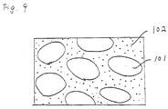
- the composites so obtained comprise magnetic metal granules 101 dispersed in an insulating phase 102, and the said granules are mutually separated by distances varying from several ⁇ m to several tens of ⁇ m. Therefore, the magnetic flux penetrating the interior of this composite material is blocked by the insulating substance, and consequently the magnetic permeability is markedly reduced.
- the magnetic material of this invention which overcomes the above-discussed and numerous other disadvantages and deficiencies of the prior art is as described in the claims. It comprises a discrete phase including grains made of a first substance which comprises a magnetic metal; and a continuous phase including a thin coating film made of a second substance which comprises a dielectric or insulating substance, the thin coating film being formed on the surface of the grains and having a mean thickness smaller than the mean particle size of the grains, wherein the grains are separated substantially from each other by the thin coating film.
- the above-mentioned magnetic material has a porosity of 5% or less, and more preferably 0.5% or less.
- the above-mentioned grains made of the first substance have a platelet shape.
- the above-mentioned grains made of the first substance have a needle-like shape.
- the above-mentioned magnetic material has a porosity of 0.1% or less.
- the above-mentioned magnetic material has a microstructure in which the grains made of the first substance are oriented.
- the above-mentioned platelet grains have an axis of easy magnetization along their major axes.
- the above-mentioned first substance contains at least one of iron and cobalt
- the grains made of the first substance have a mean particle size ensuring the formation of a single magnetic domain structure, and the axes of easy magnetization of the grains coincide with each other.
- the magnetic head of this invention which overcomes the above-discussed and numerous other disadvantages and deficiencies of the prior art, comprises a magnetic core which is made of the above-mentioned magnetic material, wherein the grains oriented in the magnetic core have their flat surface perpendicular to the running direction of the magnetic media.
- the platelet grains have an axis of easy magnetization along their major axes.
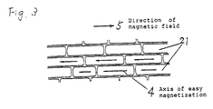
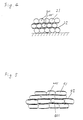
- Figures 1, 2, 3, 4 and 5 are enlarged partial sectional views of the magnetic materials of the present invention.
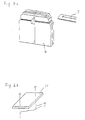
- Figure 6a is a perspective view of the magnetic head of the present invention.
- Figure 6b is an illustration showing the relation between a platelet grain that is contained in the magnetic head and the running direction of magnetic media.
- Figure 7 is an illustration of a wet magnetic pressing apparatus in magnetic field used for the preparation of the magnetic material showing in Figure 3.
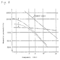
- Figure 8 is a graph showing the characteristics of the magnetic material of the present invention.
- Figure 9 is an enlarged sectional view of the conventional magnetic materials.
- a magnetic material of this invention comprises a discrete phase including grains 1 made of a first substance which comprises a magnetic metal; and a continuous phase 2 including a thin coating film made of a second substance which comprises a dielectric or insulating substance, said thin coating film being formed on the surface of said grains and having a mean thickness smaller than the mean particle size of said grains.
- the above-mentioned grains are separated substantially from each other by the thin coating film.
- Magnetic metals applicable for use as the aforementioned first substance include iron, nickel, cobalt, and alloys containing at least one of these elements.
- the appropriate alloys which can be used are Fe-Al, Fe-Si, Fe-Ni, Fe-Al-Si, Mo-Ni-Fe, Fe-Si-Al-Ni, and Si-Al-Fe-Co alloys.
- Dielectric or insulating substances applicable for use as the aforementioned second substance include aluminum oxide, aluminum nitride, silicon dioxide, magnesium oxide, manganese-zinc ferrites and nickel-zinc ferrites.
- the production of the magnetic materials comprises preparing coated grains by forming a thin coating film of the second substance on the surfaces of grains made of the first substance; compacting these coated grains into a green body; and densifying the green body. Any of the well known methods can be used to form the thin coating film made of the second substance.
- the layer of the second substance should have a mean thickness smaller than the mean particle size of the grains made of the first substance; the appropriate sizes of the grains and thin coating film will vary according to the particular purpose and type of composite material, but ordinarily the range of mean particle sizes is 0.1 - 100 ⁇ m, while the mean thickness of the thin coating film is 5-50 nm.
- the formation of the thin coating film include the formation of metal oxide films on the surfaces of metal grains by oxidation treatment, as well as the deposition onto the surfaces of metal grains, of some different metal by sputtering, etc.
- densification can be achieved by high-temperature and/or high-pressure treatment.
- densification is accomplished by treatment at a temperature of 300°C or higher under a pressure of 100 kg/cm 2 or higher.
- a portion of the thin coating films on the grains may in some cases be broken by the operations of compression, etc., thereby exposing the grain surfaces made of the first substance. Therefore, densification is ordinarily performed in such a manner that a thin coating film is again formed by the second substance or some third substance. For example, if the densification is performed in an atmosphere of an active gas, the first substance on the exposed surfaces reacts with the active gas, thereby forming an additional thin coating film.
- the active gas oxygen gas, nitrogen gas, or the mixtures thereof, for example, may be used.
- the magnetic materials formed in this manner are, for example, shown in Figure 1, wherein the grains 1 composed of the first substance are dispersed in a continuous phase 2 composed of thin films of the second substance.
- This type of magnetic material possess a synergistic combination of the properties of the magnetic metal which is the first substance and the dielectric or insulator which is the second substance.
- the proportion of the magnetic metal (i.e., first substance) in the present type of magnetic material is high, and therefore attainment of high magnetic flux density can be obtained.
- the electrical resistance is high, eddy current losses are small and magnetic permeability is high even in the high frequency regions (e.g., 2 MHz or higher).
- the surface of the magnetic material possesses electrically insulating characteristics. Furthermore, in a cross-section of this type of magnetic material, the area occupied by triangular regions (i.e., regions bounded by three or more grains) 3 is small as compared with conventional types of magnetic materials, and therefore the wear resistance of the present type of magnetic material is high.
- the porosity of the magnetic materials of the present invention should ordinarily be 5% or less (i.e., the density thereof being 95% or more), and preferably 3% or less. For applications to devices such as magnetic heads, the porosity should preferably be about 0.5%, or still more preferably about 0.1%.
- the existing pores will be closed, and the interior of the magnetic material structure will not communicate with the exterior. Moreover, the pores in the magnetic material will not communicate with each other. Therefore, the magnetic material will exhibit high mechanical strength and wear resistance as well as superior weather and chemical resistance.
- magnetic materials with the morphology shown in Figure 2 are obtained.
- platelet or platelet grains 11 with the forms of disks, oblong disks, ellipsoids of revolution or needles, are separated by a continuous phase 12 of the second substance.
- Such magnetic materials can also be prepared by using platelet or needle-like grains ab initio .
- This type of magnetic material is characterized by high hardness in the longitudinal direction of the granules and excellent wear resistance.
- This type of magnetic material can be prepared in the form shown in Figure 3, wherein platelet grains 21 possessing an axis of easy magnetization 4 are aligned so that their flat surfaces and longitudinal axes are oriented along a specified direction.
- Such magnetic materials are magnetically anisotropic.
- the magnetic permeability of such magnetic materials in the direction perpendicular to the flat surfaces (i.e., hard direction of magnetization) of the platelet grains 21 assumes a high value, exceeding the Snoeks' limit.
- the length ratio of the short axis (thickness) to the long axis (major axis) of these platelet grains should be from about 1/3 to 1/10, and the desirable length of the short axis (thickness) is 3-5 ⁇ m.
- the long axis should preferably be 5 to 10 times as large as the thickness, and the short axis is 3 to 5 times as large as the thickness.
- Magnetic anisotropy into magnetic metals include the addition of elements such as cobalt to Fe-Si-Al or other appropriate alloys, the formation of cobalt ferrites on the granule surfaces of a magnetic metal powder, varying the proportions of metallic components within the platelet grains of a magnetic metal powder so as to impart a composition gradient in the longitudinal direction of the granules, etc.
- Fe-Si-Al-Ni alloys are particularly suitable for the formation of the aforementioned platelet grains. For example, if a magnetic material containing platelet grains is to be prepared using spherical granules, then these granules are easily flattened by plastic deformation if this type of material is used.
- the magnetic material shown in the Figure 4 or 5 comprises multiple layers 301 or 401 made of grains 31 or 41 composed of the first substance, that are separated by thin film layers 32 or 42 made of the second substance. Grains 31 or 41 situated within the same layer are in mutual contact.
- the electrical resistance in a prescribed direction i. e., the direction perpendicular to the planes of the thin films
- the electrical resistance in the direction of contact between adjoining grains is extremely low. Consequently, if the direction of contact between the grains is aligned in parallel with a flux direction in a magnetic circuit, then the flux in this direction is not affected by the thin films (insulating layers), and therefore the permeability is high.
- magnetic materials with platelet grains as shown in Figure 5 still greater magnetic permeability can be attained if the direction of the flux is aligned with the longitudinal direction of the granules.
- Magnetic materials of the present invention can be used as hard or soft magnetic materials for various applications.
- magnetic materials formed from magnetic grains containing at least one of the elements of iron and cobalt and having a single magnetic domain structure, with the axes of easy magnetization aligned in a single direction can be used as permanent magnets.
- Such magnets exhibit high values of the maximum energy product (BH) max and good electrical insulating properties, and are therefore appropriate for use as magnets for motors or speakers, or for generation of magnetic fields in nuclear magnetic resonance (NMR) imaging, an important analytical technique in medicine.
- magnetic materials of the present invention are highly suitable for use as magnetic core materials for transformers and magnetic heads. In all such applications, owing to the low eddy current losses mentioned above, these magnetic materials are effective in the high frequency regions.
- the porosity of the magnetic materials should be 0.5% or less, or preferably 0.1% or less.
- Magnetic heads employing magnetic materials containing platelet grains as magnetic cores, and such that the flat surfaces of the said grains are oriented perpendicularly to the running direction of the magnetic medium, are particularly suitable.
- the platelet grain 11 shown in Figure 6b is present in the magnetic material composing the magnetic head 6 shown in Figure 6a.
- the relation between the running direction 7 of the magnetic medium and the platelet grain is shown in Figure 6b. If this type of magnetic head is used, then high output can be obtained in the high frequency regions, particularly in the 40 - 100 MHz region.
- the magnetic heads of the present invention possess excellent wear resistance.
- the sintered body so obtained possessed the cross-sectional microstructure shown in Figure 1, with the first substance 1 almost uniformly covered by the second substance 2.
- This sintered body was of high density, with a porosity of 5% or less.
- detailed examination of the polished surfaces of this sintered body revealed that the proportion of the area occupied by triangular regions (i.e., regions bounded by three or more grains) was 2.5% or less.
- the electrical resistance of the composite material so obtained was 20 Mohm or more, and the hardness of this material was 25% higher than that of a sintered body obtained by sintering the same Fe-2% Si alloy without oxidation. Furthermore, in the cutting process with a diamond blade, whereas the machining of conventional magnetic materials requires frequent dressing, machining of the composite sintered body of the present invention required dressing with only about 1/2 this frequency. Thus, the mechanical workability of this type of magnetic material is greatly improved as compared with conventional types.
- a composite sintered body was prepared by the same procedure as of Example 1, except that pressure was applied along only a single direction during the hot pressing process.
- the sintered body so obtained possessed the cross-sectional microstructure illustrated in Figure 2, with grains 11 of the first substance, originally almost spherical, deformed into flattened shapes and with the surfaces of these flattened grains covered by the second substance 12.
- This type of sintered body is anisotropic with respect to hardness, wear resistance and magnetic characteristics, the values of all of the aforementioned characteristics being 20-50% higher in the direction perpendicular to the flat surfaces of the grains as compared with directions parallel to these flat surfaces.
- transformers were fabricated with the aforementioned composite material as magnetic cores, the transformers so obtained had excellent magnetic characteristics. Moreover, since the porosity of the composite material was low, the required core volume was decreased and hence losses were reduced.
- the composite sintered body so obtained was of high density, with a porosity of 0.5% or less. Moreover, detailed examination of the polished surfaces of this sintered body revealed that the proportion of the area occupied by triangular regions was 0.3% or less.
- the electrical resistance of the composite sintered body so obtained was 20 Mohm or more, and the hardness of this sintered body was 25% higher than that of a sintered body obtained by sintering the same Fe-5% Al alloy without oxidation.
- the hot pressing was performed at a temperature of 800°C, the porosity of the sintered body so obtained was 0.1%, and the thickness of the oxide film was approximately 0.2 ⁇ m.
- the saturated magnetic flux density of this composite material was 0.15 T (1500 G) or more. Therefore, the aforementioned composite material is applicable for use as magnetic heads for audio equipment.
- a composite sintered body was prepared by the same procedure as in Example 3, except that pressure was applied along only a single direction during the hot pressing process.
- the grains of the first substance originally almost spherical, were deformed into flattened shapes (platelet shapes).
- the aspect ratio of these platelet grains was about 2. This aspect ratio can be varied by appropriately adjusting the pressure and direction of compression when hot pressing is performed, and in fact even grains with an aspect ratio of approximately 10 could be obtained in this manner.
- This type of sintered body is anisotropic with respect to hardness, wear resistance and magnetic characteristics, the values of all of the aforementioned characteristics being 20-50% higher in the direction perpendicular to the flat surfaces of the grains as compared with directions parallel to these flat surfaces.
- magnetic characteristics were also improved as compared with heads fabricated from conventional magnetic materials, for example, the magnetic permeability was approximately 10% higher and the magnetic reluctance approximately 20% lower.
- wear resistance was also approximately 15% higher.
- the flat surfaces of the grains are parallel the plane of the tape running over the magnetic head, then the magnetic head output in the frequency range of 10-30 MHz is improved by 1-1.5 dB, and demagnetization is reduced.
- the magnetic head output in the range of 40-100 MHz is vastly improved.
- This type of magnetic head is not only suitable for audio equipment but is also particularly appropriate for use in high-definition video tape recorders and computers.
- a powder consisting of grains made of Si-Al-Ni-Fe (first substance) with composition of Si:Al:Ni:Fe 6:4:3:87 (weight ratio), was prepared by the following procedure. First, the aforementioned components were mixed and melted by high frequency induction heating, the ingots so obtained were crushed with a hammer mill, and grains of 61 ⁇ m (#250 mesh) or smaller and a mean particle size of approximately 20 ⁇ m were classified from the crushed ingot material.
- This powder was heated at a temperature of 1200-1300°C in an inert gas atmosphere and the grains were flattened by allowing the hot powder to impinge upon a cooling plate at a high velocity.
- the shapes of the grains flattened in the aforementioned manner were investigated with a scanning electron microscope or a specific surface measuring device (BET specific surface gauge), etc., and the aspect ratio was determined. These observations revealed that the powder was composed of platelet grains of a diameter of approximately 40 ⁇ m and a thickness of 3-4 ⁇ m, thus, the aspect ratio of the grains was approximately 10-15.
- the specific surface of the original grains was 0.04-0.05 m 2 /g in each case, and after the flattening process, the specific surface of the grains of the Si-Al-Ni-Fe alloy was approximately 0.1 m 2 /g, while that of the Si-Al-Fe alloy was approximately 0.2 m 2 /g.
- the specific surface area of the Si-Al-Fe alloy grains was of the same order as that of the grains of Si-Al-Ni-Fe alloy. This is attributed to the fact, verified by scanning electron microscopy, that the powder prepared from the former alloy contained a large number of comparatively small grains, and, moreover, numerous indentations and irregularities were present on the grain surfaces. This was due to the greater hardness and brittleness of the Si-Al-Fe alloy, which caused breakage of grains during the flattening process.
- the saturated magnetic flux density of the aforementioned Si-Al-Fe alloy is approximately 1 T (10,000 G), while that of the aforementioned Si-Al-Ni-Fe alloy is approximately 1.5 T (15,000 G), and the wear resistance of both alloys is about 2-10 times that of the Permalloy.
- another mold was prepared by the same process using Si-Al-Ni-Fe alloy powder with platelet grains but without formation of an insulating coating film.
- the aforementioned three varieties of moldings were subjected to hot pressing for 3 hours in an inert gas atmosphere at a temperature in the range of 1200-1300°C under a pressure of 30 MPa.
- the direction of compression in this process was the same as that of the initial molding process.
- the sintered bodies so obtained were of high density, with porosity of 1% or less. Examination of cross-sections of these sintered bodies with a scanning electron microscope revealed that the sintered body prepared from the platelet grains of Si-Al-Ni-Fe alloy upon which an oxide insulating layer had been formed possessed a microstructure consisting of magnetic metal grains coated with an aluminum oxide insulating layer of a thickness of 10-30 nm, arranged in the manner of stacked bricks, sintered to a high density, and forming magnetic layers composed of magnetic metal grains of thickness of 3-5 ⁇ m.
- the sintered body prepared from the grains of Si-Al-Fe alloy which had undergone oxidation treatment after the flattening process possessed a microstructure characterized by sporadic severing of the oxide insulating film with mutual interpenetration of metal grains and the insulating film.
- the sintered body prepared from the platelet grains of Si-Al-Ni-Fe alloy upon which no oxide insulating coating film had been formed displayed a microstructure characterized by oriented plate-shaped metal grains.
- the electrical resistances of the sintered bodies obtained in the aforementioned manner were measured.
- the sintered body (thickness of approximately 5 mm, length of approximately 30 mm) prepared from the platelet grains of Si-Al-Ni-Fe alloy upon which an oxide insulating layer had been formed exhibited a high resistance of approximately 1 Mohm in directions both perpendicular and parallel to the flat faces of the grains.
- the electrical resistance of the insulating layer itself was in the order of several tens of megohms. However, for the other two varieties of sintered bodies, the electrical resistances were no greater than the order of several hundred microhms, or the same order as that of ordinary magnetic metals.
- the magnetic characteristics of these sintered bodies were measured.
- the magnetic permeability in the frequency range of 10 kHz - 5 MHz was approximately 100-300 in the direction perpendicular to the flat surfaces of the grains and 1000-1500 in directions parallel to the flat surfaces; the saturated magnetic flux density of the sintered body was 1.5 T (15,000 G), i.e., of the same order as that of the magnetic metal used as original raw material.
- the other two varieties of sintered bodies exhibited magnetic permeabilities of several hundred to 0.1 T (1,000 G) in the low frequency region from 10 Hz to 1 kHz, whereas at frequencies beyond 1 kHz the magnetic permeabilities of these sintered bodies dropped to the order of several tens or less.
- alloy powder A and B Two varieties of alloy powder A and B were prepared as follows using the same Si-Al-Ni-Fe alloy as used in Example 5. First, ingots prepared in the same manner as in Example 5 were cut into blocks of appropriate size, then these blocks were melted by high frequency induction heating, and so-called nitrogen-atomized globular powder was prepared by using high-pressure argon gas to blow the molten alloy into a nitrogen gas atmosphere. This nitrogen-atomized globular powder was classified, the fine powder of mesh #250 or less was collected, and this was designated as alloy powder A.
- the other variety of powder was prepared by rough crushing of blocks from the same type of ingot in a hammer mill, followed by fine pulverization of this material in a jet mill, using nitrogen as the carrier gas, after which the powder so obtained was classified and the fine powder of 61 ⁇ m (mesh #250) or less was collected; this variety was designated as alloy powder B.
- alloy powder A was composed of globular grains of fairly uniform size, with a mean grain diameter of approximately 15-16 ⁇ m; on the other hand, alloy powder B was composed of block-shaped grains of irregularly assorted forms with various grain sizes, ranging from fine to coarse grains.
- alloy powders A and B were separately subjected to flattening treatment in a ball mill for 50 hours.
- the shape, aspect ratio and other features of the platelet powder grains so obtained was evaluated by means of a scanning electron microscope and a specific surface area measuring device.
- the results revealed that the platelet granular powder prepared by using alloy powder A was composed almost entirely of oblong disks approximately 3-5 ⁇ m in thickness, and approximately 30 ⁇ m in long axis (major axis); the distribution of grain diameters was narrow, extending over a range of 20-40 ⁇ m, and the aspect ratio was approximately 10.
- the platelet granular powder prepared by using alloy powder B was also composed of oval grains with flat surfaces, but the size of of these granules was very irregular, the diameters being distributed over the wide range of 3-60 ⁇ m and the thicknesses ranging from 0.5 to 20 ⁇ m, while the surfaces of the granules was irregular.
- the powders so obtained were then subjected to wet molding by the same method as in Example 5, thereby orienting the platelet grains, and the moldod samples so obtained were placed in a hot-pressing mold and hot-pressed for three hours at 1200-1300°C under a pressure of 300 kg/cm 2 , thus obtaining two varieties of composite sintered bodies.
- a magnetic powder with globular grains bearing insulating films was prepared from a globular powder with the same composition as alloy powder A and a grain size of about 20 ⁇ m by surface oxidation treatment. Then, sintered compacts were obtained from this powder in the same manner as described above. Then, magnetic heads of the above-described form were fabricated from these sintered bodies, and the performance characteristics of these heads were evaluated. The results showed that this magnetic head provided 3-5 dB higher output at the same frequency as compared with the magnetic heads prepared from the above-mentioned alloy powder B without oxidation treatment, but exhibited lower output than the magnetic heads fabricated with the platelet grain powder obtained from alloy powder A.
- the thickness of the oxide film so formed was estimated to be approximately 10-20 nm on the basis of calculations from the weight increase and specific surface area of the powder as well as Auger electron spectroscopy.
- the aforementioned powder with grains covered by an oxide film was added to a glycerin solution and stirred into a slurry. Then, rectangular parallelopipedal moldings were obtained from this slurry using the wet magnetic pressing apparatus schematically illustrated in Figure 7. That is, the slurry containing the platelet granular powder 11 was poured into the space between a pair of wet molds 9, 90 and a pressure of 1000 kg/cm 2 was applied from above and below, expelling only the solvent 8 of the slurry from the minute holes of the molds, and a magnetic field of 796,000 A/m (10,000 Oe), perpendicular to the direction of compression, was simultaneously applied with a magnet 10.
- the resulting molding has the form shown in Figure 3, wherein the flat surfaces of the flattened grains 21 are oriented perpendicularly to the direction of compression, while owing to the impressed magnetic field, the direction of the axes of easy magnetization 4 are aligned with the direction of the impressed magnetic field 5.
- the sintered density and porosity of the material were measured. The results showed that the relative density of these sintered bodies was 99.5% or more, and the porosity was 0.5%.
- the electrical resistance of this composite material was 20 Mohm or more, and the saturated magnetic flux density was 1 T (10,000 G) or more.
- the magnetic permeability of this composite material was measured, i. e., the magnetic permeabilities in directions parallel and perpendicular to the flat surfaces of the powder grains were measured separately, with the results shown in Figure 8.
- the magnetic permeability B in the direction parallel to the flat surfaces of the powder granules i. e., the direction of the axes of easy magnetization 4
- the magnetic permeability A in the direction perpendicular to the flat surfaces of the powder grains was 1300 at 10 MHz and 1200 at 20 MHz.
- magnetic permeabilities well above 1000 were obtained throughout this frequency range.
- Magnetic heads for video devices were fabricated using the aforementioned composite material as magnetic cores.
- Three varieties of such magnetic heads were fabricated, i. e., one variety with the running direction of the magnetic tape parallel to the flat surfaces of the powder grains designated as magnetic head A, a second variety with the running direction of the magnetic tape perpendicular to the flat surfaces of the powder grains, designated as magnetic head B, and a third variety with the running direction of the magnetic tape inclined at an angle of nearly 45° to the flat surfaces of the powder grains, designated as magnetic head C.
- a silicon-aluminum-iron alloy (first substance), with composition Si:Al:Fe 10:6:84 (weight ratio) in the form of a globular powder [61 ⁇ m (mesh #250 or less, mean grain size 30 ⁇ m)] was mixed with an organic binder and blended into a slurry. Then, using the doctor blade method, sheets 40 ⁇ m in thickness were prepared from this slurry. After drying, these sheets were heated in a non-oxidizing atmosphere at a temperature in the range of 500-600°C, thereby effecting thermal decomposition of the binder and removing the said binder from the sheets. Each of these sheets was composed of a dense one-granule layer of globular alloy grains.
- a 30 nm-thick film of silicon dioxide (the second substance) was formed on the surfaces of these sheets by sputtering. Then, above each of these silicon-dioxide coated alloy powder layers, another layer of alloy powder was formed by the aforementioned procedure, and after removal of the binder still another silicon dioxide film was deposited on this sandwich.
- This process was performed three times, thereby creating laminates of magnetic metal powder and an insulator, made of silicon dioxide. Next, these laminates were hot-pressed for two hours at 1000°C in a non-oxidizing atmosphere, using a pressure of 100 kg/cm 2 applied in the direction perpendicular to the sheet surfaces, and thereby obtaining high-density composite sintered bodies.
- the electrical resistance of these composites in the direction perpendicular to the magnetic layers was 1 Mohm, a large value comparable with that of ordinary insulators.
- the electrical resistance in directions parallel to the magnetic layers was several tens of microhms (i.e., of the order of the electrical resistance values exhibited by ordinary metals) along the magnetic layers, and several tens of megohms along the insulating layers.
- the magnetic characteristics of these composites were measured.
- the magnetic permeability at the frequency of 10 kHz was 50 in the direction perpendicular to the magnetic metal layers, and 1500 in directions parallel to the magnetic metal layers.
- the saturated magnetic flux density of these composites was 1.1 T (11,000 G), nearly the same as that of the magnetic metal which constituted the original powdered raw material.
- the thickness of the silicon dioxide film was 5-20 nm.
- the aforementioned coated powder was added to a glycerin solution and the mixture was stirred into a slurry. Then, rectangular parallelopipedal specimens were molded from this slurry using the same wet magnetic pressing apparatus as was used in Example 7.
- the wet magnetic pressing process oriented the long axes of the needle granules of the acicular powder along the direction of the applied magnetic field, thus, molded compacts with a desired orientation were obtained.
- composite B composite permanent magnets
- the magnetic characteristics of two varieties of composites obtained in the aforementioned manner were measured.
- the maximum energy product (BH)max of composite A was 50-60 MGOe; this value is even greater than the previously reported values of (BH)max for sintered Nd-Fe-B magnets (approximately 3.18x10 9 A/m (40 MGOe)).
- the value of (BH)max for composite B was 5.17 x 10 8 A/m (6.5 MGOe).
- This composite A exhibited not only a large value of (BH)max but also high electrical resistivities of the order of 10 8 to 10 9 ohm-cm, of the same magnitude as ordinary insulators.
Claims (11)
- Matière magnétique comprenant une phase discrète et une phase continue,dans laquelle la phase discrète comprend des grains faits d'une première substance qui est principalement composée de Fe et qui contient au moins un des éléments suivants Al, Si, Ni, Mo et Co ; la phase continue comprend un film de revêtement mince diélectrique et un film de revêtement mince diélectrique supplémentaire qui sont formés sur la surface des grains ; les grains sont séparés sensiblement les uns des autres par la phase continue, et l'épaisseur du film de revêtement mince diélectrique et du film de revêtement mince diélectrique supplémentaire est plus petite que la taille moyenne de particule des grains,dans laquelle le film de revêtement mince diélectrique est fait d'un oxyde métallique ou de nitrure ou d'un alliage de ces derniers formé sur la surface des grains faits de la première substance, ledit film de revêtement étant formé en chauffant les grains dans un gaz actif, par un processus de pulvérisation cathodique, ou par un processus d'alliage mécanique, le gaz actif étant au moins un gaz sélectionné dans le groupe formé du gaz d'oxygène et du gaz d'azote,dans laquelle le film de revêtement mince diélectrique supplémentaire est fait d'un oxyde ou d'un nitrure de la première substance, etdans laquelle la matière magnétique est formée par un pressage à chaud des grains dans un gaz actif, le gaz actif étant au moins un gaz sélectionné dans le groupe formé du gaz d'oxygène et du gaz d'azote, de sorte que le film de revêtement mince diélectrique supplémentaire est formé sur une surface exposée de la surface des grains par la réaction avec le gaz actif, la surface exposée étant créée par rupture du film de revêtement mince diélectrique sur les grains pendant le pressage à chaud.
- Matière magnétique selon la revendication 1, ayant une porosité de 5 % ou moins.
- Matière magnétique selon la revendication 1, dans laquelle lesdits grains sont des grains anisotropes.
- Matière magnétique selon la revendication 3, dans laquelle lesdits grains anisotropes sont formés par le pressage à chaud qui est effectué de façon uniaxiale.
- Matière magnétique selon la revendication 3, dans laquelle les grains sont prétraités avant la formation du film de revêtement mince pour obtenir leur forme anisotrope.
- Matière magnétique selon la revendication 1, dans laquelle lesdits grains faits de la première substance ont une forme de plaquette.
- Matière magnétique selon la revendication 1, dans laquelle lesdits grains faits de la première substance ont une forme d'aiguille.
- Matière magnétique selon la revendication 1, dans laquelle ladite première substance contient du fer et du cobalt, lesdits grains faits de la première substance ont une taille moyenne de particule assurant la formation d'une structure unique de domaine magnétique, et les axes de magnétisation privilégiée desdits grains sont parallèles les uns aux autres.
- Matière magnétique selon la revendication 5, ayant une microstructure dans laquelle lesdits grains faits de la première substance sont orientés.
- Tête magnétique comprenant un noyau magnétique qui est fait d'une matière magnétique selon l'une des revendications 3 à 6, dans laquelle la surface plate desdits grains orientés dans le noyau magnétique est perpendiculaire à la direction d'avance du support magnétique.
- Tête magnétique selon la revendication 10, dans laquelle lesdits grains en plaquettes ont un axe de magnétisation privilégiée le long de leurs axes principaux.
Applications Claiming Priority (10)
| Application Number | Priority Date | Filing Date | Title |
|---|---|---|---|
| JP147906/89 | 1989-06-09 | ||
| JP14790689 | 1989-06-09 | ||
| JP18642389 | 1989-07-19 | ||
| JP186423/89 | 1989-07-19 | ||
| JP28055389 | 1989-10-26 | ||
| JP280553/89 | 1989-10-26 | ||
| JP288357/89 | 1989-11-06 | ||
| JP28835789 | 1989-11-06 | ||
| JP63154/90 | 1990-03-14 | ||
| JP6315490 | 1990-03-14 |
Publications (2)
| Publication Number | Publication Date |
|---|---|
| EP0401835A1 EP0401835A1 (fr) | 1990-12-12 |
| EP0401835B1 true EP0401835B1 (fr) | 1997-08-13 |
Family
ID=27523758
Family Applications (1)
| Application Number | Title | Priority Date | Filing Date |
|---|---|---|---|
| EP19900110828 Expired - Lifetime EP0401835B1 (fr) | 1989-06-09 | 1990-06-07 | Matériel magnétique |
Country Status (4)
| Country | Link |
|---|---|
| US (2) | US5238507A (fr) |
| EP (1) | EP0401835B1 (fr) |
| KR (1) | KR910001820A (fr) |
| DE (1) | DE69031250T2 (fr) |
Families Citing this family (47)
| Publication number | Priority date | Publication date | Assignee | Title |
|---|---|---|---|---|
| DE69031250T2 (de) * | 1989-06-09 | 1997-12-04 | Matsushita Electric Ind Co Ltd | Magnetisches Material |
| JPH05109520A (ja) * | 1991-08-19 | 1993-04-30 | Tdk Corp | 複合軟磁性材料 |
| EP0541887B1 (fr) * | 1991-08-19 | 1996-05-22 | TDK Corporation | Procédé de preperation d'un matériau composite magnétiquement doux et matériau composite magnétiquement doux |
| WO1993011531A1 (fr) * | 1991-12-02 | 1993-06-10 | Nikko Kyodo Company, Limited | Tete magnetique a film mince |
| US5798176A (en) * | 1993-09-13 | 1998-08-25 | Kao Corporation | Magnetic recording medium |
| JP2961034B2 (ja) * | 1993-09-16 | 1999-10-12 | アルプス電気株式会社 | 磁気ヘッド |
| GB9506909D0 (en) * | 1995-04-04 | 1995-05-24 | Scient Generics Ltd | Spatial magnetic interrogation system |
| US7370797B1 (en) * | 1996-05-31 | 2008-05-13 | Scott Lindsay Sullivan | Pill printing and identification |
| JPH118111A (ja) * | 1997-06-17 | 1999-01-12 | Tdk Corp | バルントランス用コア材料、バルントランス用コアおよびバルントランス |
| US6051324A (en) * | 1997-09-15 | 2000-04-18 | Lockheed Martin Energy Research Corporation | Composite of ceramic-coated magnetic alloy particles |
| US6188549B1 (en) | 1997-12-10 | 2001-02-13 | Read-Rite Corporation | Magnetoresistive read/write head with high-performance gap layers |
| JP4457425B2 (ja) * | 1998-09-08 | 2010-04-28 | アイシン精機株式会社 | モータの電機子コアとその電機子コアを用いたブラシ付直流モータ |
| AU8016600A (en) * | 1999-10-12 | 2001-04-23 | Precise Power Corporation | Method and apparatus for preparation of magnetic material |
| DE19960095A1 (de) * | 1999-12-14 | 2001-07-05 | Bosch Gmbh Robert | Gesinterter weichmagnetischer Verbundwerkstoff und Verfahren zu dessen Herstellung |
| JP4684461B2 (ja) | 2000-04-28 | 2011-05-18 | パナソニック株式会社 | 磁性素子の製造方法 |
| JP4422953B2 (ja) * | 2002-08-22 | 2010-03-03 | 株式会社日立製作所 | 永久磁石の製造方法 |
| CA2418497A1 (fr) * | 2003-02-05 | 2004-08-05 | Patrick Lemieux | Pieces magnetiques a aimantation temporaire a haute performance fabriquees a l'aide de la technologie de la metallurgie des poudres pour applications c.a. |
| JP4265358B2 (ja) * | 2003-10-03 | 2009-05-20 | パナソニック株式会社 | 複合焼結磁性材の製造方法 |
| WO2006011949A2 (fr) * | 2004-06-24 | 2006-02-02 | University Of Delaware | Nanocomposites faiblement ferromagnetiques haute frequence |
| US20070036669A1 (en) * | 2004-09-03 | 2007-02-15 | Haruhisa Toyoda | Soft magnetic material and method for producing the same |
| JP4650073B2 (ja) * | 2005-04-15 | 2011-03-16 | 住友電気工業株式会社 | 軟磁性材料の製造方法、軟磁性材料および圧粉磁心 |
| JP4693732B2 (ja) * | 2005-10-11 | 2011-06-01 | キヤノン電子株式会社 | 複合型金属成形体およびその製造方法 |
| JP4665751B2 (ja) * | 2005-12-22 | 2011-04-06 | 株式会社日立製作所 | 高抵抗磁石を用いたmri装置 |
| WO2009025787A2 (fr) * | 2007-08-20 | 2009-02-26 | Diemat, Inc. | Adhésifs ayant une conductivité thermique améliorée par des charges mélangées d'argent |
| KR101105595B1 (ko) * | 2008-08-13 | 2012-01-18 | 주식회사 이엠따블유 | 페라이트 제조방법 |
| US20100061877A1 (en) * | 2008-09-11 | 2010-03-11 | Mariam Sadaka | Magnetic materials, and methods of formation |
| EP2589450B1 (fr) * | 2010-06-30 | 2019-08-28 | Panasonic Intellectual Property Management Co., Ltd. | Matériau magnétique composite et processus de production de celui-ci |
| US8480815B2 (en) | 2011-01-14 | 2013-07-09 | GM Global Technology Operations LLC | Method of making Nd-Fe-B sintered magnets with Dy or Tb |
| US8362866B2 (en) * | 2011-01-20 | 2013-01-29 | Taiyo Yuden Co., Ltd. | Coil component |
| US10022789B2 (en) * | 2011-06-30 | 2018-07-17 | Persimmon Technologies Corporation | System and method for making a structured magnetic material with integrated particle insulation |
| US9364895B2 (en) * | 2011-06-30 | 2016-06-14 | Persimmon Technologies Corporation | System and method for making a structured magnetic material via layered particle deposition |
| JP5082002B1 (ja) * | 2011-08-26 | 2012-11-28 | 太陽誘電株式会社 | 磁性材料およびコイル部品 |
| KR101287355B1 (ko) * | 2011-09-07 | 2013-07-18 | (주)창성 | 연자성 금속 분말을 이용한 코어 제조용 엘립스 형태의 단위블록 및 이를 이용하여 제조된 분말 자성코어 |
| US10476324B2 (en) | 2012-07-06 | 2019-11-12 | Persimmon Technologies Corporation | Hybrid field electric motor |
| JP6115057B2 (ja) * | 2012-09-18 | 2017-04-19 | Tdk株式会社 | コイル部品 |
| DE102013205280A1 (de) * | 2013-03-26 | 2014-10-02 | Siemens Aktiengesellschaft | Permanentmagnet und Verfahren zur Herstellung des Permanentmagneten |
| KR102402075B1 (ko) * | 2013-09-30 | 2022-05-25 | 퍼시몬 테크놀로지스 코포레이션 | 구조화된 자성 재료를 사용하는 구조체 및 이의 제조 방법 |
| US10570494B2 (en) | 2013-09-30 | 2020-02-25 | Persimmon Technologies Corporation | Structures utilizing a structured magnetic material and methods for making |
| KR102198528B1 (ko) * | 2015-05-19 | 2021-01-06 | 삼성전기주식회사 | 코일 전자부품 및 그 제조방법 |
| KR102525078B1 (ko) * | 2016-04-11 | 2023-04-25 | 퍼시몬 테크놀로지스 코포레이션 | 재료, 고정자 코어, 고정자 권선 코어 |
| US9803139B1 (en) * | 2016-06-24 | 2017-10-31 | General Electric Company | Process for removing aluminum-silicon coatings from metallic structures, and related processes for preparing magnetic components |
| JP2019161183A (ja) | 2018-03-16 | 2019-09-19 | 株式会社東芝 | 複数の扁平磁性金属粒子、圧粉材料及び回転電機 |
| US11127524B2 (en) | 2018-12-14 | 2021-09-21 | Hong Kong Applied Science and Technology Research Institute Company Limited | Power converter |
| FR3095285B1 (fr) | 2019-04-19 | 2022-11-11 | Linxens Holding | Module de capteur biométrique pour carte à puce et procédé de fabrication d’un tel module |
| US11926880B2 (en) | 2021-04-21 | 2024-03-12 | General Electric Company | Fabrication method for a component having magnetic and non-magnetic dual phases |
| US11661646B2 (en) | 2021-04-21 | 2023-05-30 | General Electric Comapny | Dual phase magnetic material component and method of its formation |
| WO2023287429A1 (fr) * | 2021-07-16 | 2023-01-19 | Ferric Inc. | Matériau composite à base de polymère ferromagnétique et structures le comprenant |
Citations (3)
| Publication number | Priority date | Publication date | Assignee | Title |
|---|---|---|---|---|
| DE360361C (de) * | 1922-10-02 | Ludwig Bauer & Co | Form zur Herstellung von mit Stirnfalz und Nut versehenen Zementroehren mit flacher Sohle | |
| EP0088992A2 (fr) * | 1982-03-17 | 1983-09-21 | Asea Ab | Procédé de fabrication d'un objet en matériau magnétique doux par agglomération d'une masse de poudre |
| EP0177276A2 (fr) * | 1984-09-29 | 1986-04-09 | Kabushiki Kaisha Toshiba | Noyau de poudre magnétique comprimé |
Family Cites Families (24)
| Publication number | Priority date | Publication date | Assignee | Title |
|---|---|---|---|---|
| US3255052A (en) * | 1963-12-09 | 1966-06-07 | Magnetics Inc | Flake magnetic core and method of making same |
| US3999216A (en) * | 1970-07-30 | 1976-12-21 | Eastman Kodak Company | Material for magnetic transducer heads |
| US3739445A (en) * | 1970-12-29 | 1973-06-19 | Chromalloy American Corp | Powder metal magnetic pole piece |
| US3814598A (en) * | 1970-12-29 | 1974-06-04 | Chromalloy American Corp | Wear resistant powder metal magnetic pole piece made from oxide coated fe-al-si powders |
| US3933536A (en) * | 1972-11-03 | 1976-01-20 | General Electric Company | Method of making magnets by polymer-coating magnetic powder |
| US3892600A (en) * | 1973-06-22 | 1975-07-01 | Gen Electric | Annealed coated air-stable cobalt-rare earth alloy particles |
| US3948690A (en) * | 1973-09-11 | 1976-04-06 | Westinghouse Electric Corporation | Molded magnetic cores utilizing cut steel particles |
| US4133677A (en) * | 1976-04-05 | 1979-01-09 | Toda Kogyo Corp. | Process for producing acicular magnetic metallic particle powder |
| US4177089A (en) * | 1976-04-27 | 1979-12-04 | The Arnold Engineering Company | Magnetic particles and compacts thereof |
| JPS5913732B2 (ja) * | 1977-07-05 | 1984-03-31 | コニカ株式会社 | 鉄粉現像担体及びその製造方法並びに現像剤と画像形成方法 |
| JPS55152155A (en) * | 1979-05-16 | 1980-11-27 | Sumitomo Special Metals Co Ltd | Fine crystalline strip material for high permeability magnetic material, preparation and product thereof |
| JPS55156029A (en) * | 1979-05-25 | 1980-12-04 | Matsushita Electric Ind Co Ltd | Manufacture of resin dispersive film laminate |
| JPS5832767B2 (ja) * | 1980-01-24 | 1983-07-15 | ヤマハ株式会社 | 硬質磁性材料の製法 |
| US4323395A (en) * | 1980-05-08 | 1982-04-06 | Li Chou H | Powder metallurgy process and product |
| JPS57143729A (en) * | 1981-02-27 | 1982-09-06 | Fuji Photo Film Co Ltd | Magnetic recording medium |
| JPS57150130A (en) * | 1981-03-12 | 1982-09-16 | Fuji Photo Film Co Ltd | Magnetic recording medium |
| US4543208A (en) * | 1982-12-27 | 1985-09-24 | Tokyo Shibaura Denki Kabushiki Kaisha | Magnetic core and method of producing the same |
| JPS59182972A (ja) * | 1983-04-04 | 1984-10-17 | Kawasaki Steel Corp | 鉄損特性の優れた一方向性けい素鋼板の製造方法 |
| US4601753A (en) * | 1983-05-05 | 1986-07-22 | General Electric Company | Powdered iron core magnetic devices |
| JPS60152656A (ja) * | 1984-01-19 | 1985-08-10 | Namiki Precision Jewel Co Ltd | 高性能磁性材料及びその製造方法 |
| JPH0618059B2 (ja) * | 1984-04-11 | 1994-03-09 | 株式会社日立製作所 | 垂直磁気記録媒体 |
| JPS60261031A (ja) * | 1984-06-07 | 1985-12-24 | Tdk Corp | 磁気記録媒体 |
| DE3603061A1 (de) * | 1985-03-01 | 1986-09-04 | Bbc Brown Boveri Ag, Baden, Aargau | Verfahren zur herstellung eines weichmagnetischen verbundwerkstoffes mit geringen wirbelstromverlusten auf der basis eines weichmagnetischen, metallischen werkstoffs und danach hergestellter verbundwerkstoff |
| DE69031250T2 (de) * | 1989-06-09 | 1997-12-04 | Matsushita Electric Ind Co Ltd | Magnetisches Material |
-
1990
- 1990-06-07 DE DE1990631250 patent/DE69031250T2/de not_active Expired - Fee Related
- 1990-06-07 EP EP19900110828 patent/EP0401835B1/fr not_active Expired - Lifetime
- 1990-06-08 US US07/535,082 patent/US5238507A/en not_active Expired - Fee Related
- 1990-06-09 KR KR1019900008474A patent/KR910001820A/ko not_active Application Discontinuation
-
1992
- 1992-11-19 US US07/978,564 patent/US5350628A/en not_active Expired - Lifetime
Patent Citations (3)
| Publication number | Priority date | Publication date | Assignee | Title |
|---|---|---|---|---|
| DE360361C (de) * | 1922-10-02 | Ludwig Bauer & Co | Form zur Herstellung von mit Stirnfalz und Nut versehenen Zementroehren mit flacher Sohle | |
| EP0088992A2 (fr) * | 1982-03-17 | 1983-09-21 | Asea Ab | Procédé de fabrication d'un objet en matériau magnétique doux par agglomération d'une masse de poudre |
| EP0177276A2 (fr) * | 1984-09-29 | 1986-04-09 | Kabushiki Kaisha Toshiba | Noyau de poudre magnétique comprimé |
Non-Patent Citations (1)
| Title |
|---|
| Kirk-Othmer, Encyclopedia of Chmeical Technology, 3rd edition, volume 12, pages 410-412 * |
Also Published As
| Publication number | Publication date |
|---|---|
| KR910001820A (ko) | 1991-01-31 |
| DE69031250D1 (de) | 1997-09-18 |
| DE69031250T2 (de) | 1997-12-04 |
| US5350628A (en) | 1994-09-27 |
| EP0401835A1 (fr) | 1990-12-12 |
| US5238507A (en) | 1993-08-24 |
Similar Documents
| Publication | Publication Date | Title |
|---|---|---|
| EP0401835B1 (fr) | Matériel magnétique | |
| US5183631A (en) | Composite material and a method for producing the same | |
| KR20120115490A (ko) | 자석용 분말 | |
| US5227235A (en) | Composite soft magnetic material and coated particles therefor | |
| JPH05109520A (ja) | 複合軟磁性材料 | |
| KR101345496B1 (ko) | 자석용 분말, 분말 성형체, 희토류-철-붕소계 합금재, 자석용 분말의 제조 방법, 및 희토류-철-붕소계 합금재의 제조 방법 | |
| WO2020026949A1 (fr) | Poudre magnétique à aimantation douce, poudre d'alliage nanocristallin à base de fer, composant magnétique et noyau à poudre | |
| JPH044387B2 (fr) | ||
| JP2009185312A (ja) | 複合軟磁性材料、それを用いた圧粉磁心、およびそれらの製造方法 | |
| JP4968519B2 (ja) | 永久磁石およびその製造方法 | |
| Ding et al. | Magnetic properties of Ba-and Sr-hexaferrite prepared by mechanical alloying | |
| EA014583B1 (ru) | Композиция для получения спеченного постоянного магнита, спеченный постоянный магнит и способ его получения | |
| JPH06267723A (ja) | 複合軟磁性材料 | |
| US4379003A (en) | Magnetic devices by selective reduction of oxides | |
| JPH07135106A (ja) | 磁 心 | |
| Raybould et al. | Factors affecting the magnetic properties of consolidated amorphous powder cores | |
| JPH0547541A (ja) | 磁性コアの製造方法 | |
| JPS5916306A (ja) | 電磁気装置用粉末コア−の製法 | |
| JPH03150810A (ja) | ラインフィルタ | |
| JP2022168543A (ja) | 磁性金属/フェライトコンポジット及びその製造方法 | |
| JPH03278407A (ja) | 複合磁性材料 | |
| Maki et al. | Microstructures and magnetic properties of Sm-Fe-N thick films produced by the aerosol deposition method | |
| JP2014207341A (ja) | 炭化鉄材、炭化鉄材の製造方法、及び磁石 | |
| WO2022201964A1 (fr) | Poudre magnétique douce, noyau à poudre de fer la contenant, et procédé de production de poudre magnétique douce | |
| JPH05267036A (ja) | 複合磁性材料 |
Legal Events
| Date | Code | Title | Description |
|---|---|---|---|
| PUAI | Public reference made under article 153(3) epc to a published international application that has entered the european phase |
Free format text: ORIGINAL CODE: 0009012 |
|
| AK | Designated contracting states |
Kind code of ref document: A1 Designated state(s): DE FR GB |
|
| 17P | Request for examination filed |
Effective date: 19910215 |
|
| 17Q | First examination report despatched |
Effective date: 19930306 |
|
| GRAG | Despatch of communication of intention to grant |
Free format text: ORIGINAL CODE: EPIDOS AGRA |
|
| GRAH | Despatch of communication of intention to grant a patent |
Free format text: ORIGINAL CODE: EPIDOS IGRA |
|
| GRAH | Despatch of communication of intention to grant a patent |
Free format text: ORIGINAL CODE: EPIDOS IGRA |
|
| GRAA | (expected) grant |
Free format text: ORIGINAL CODE: 0009210 |
|
| AK | Designated contracting states |
Kind code of ref document: B1 Designated state(s): DE FR GB |
|
| REF | Corresponds to: |
Ref document number: 69031250 Country of ref document: DE Date of ref document: 19970918 |
|
| ET | Fr: translation filed | ||
| PLBE | No opposition filed within time limit |
Free format text: ORIGINAL CODE: 0009261 |
|
| STAA | Information on the status of an ep patent application or granted ep patent |
Free format text: STATUS: NO OPPOSITION FILED WITHIN TIME LIMIT |
|
| 26N | No opposition filed | ||
| REG | Reference to a national code |
Ref country code: GB Ref legal event code: IF02 |
|
| PGFP | Annual fee paid to national office [announced via postgrant information from national office to epo] |
Ref country code: DE Payment date: 20060601 Year of fee payment: 17 |
|
| PGFP | Annual fee paid to national office [announced via postgrant information from national office to epo] |
Ref country code: GB Payment date: 20060607 Year of fee payment: 17 |
|
| PGFP | Annual fee paid to national office [announced via postgrant information from national office to epo] |
Ref country code: FR Payment date: 20060608 Year of fee payment: 17 |
|
| GBPC | Gb: european patent ceased through non-payment of renewal fee |
Effective date: 20070607 |
|
| REG | Reference to a national code |
Ref country code: FR Ref legal event code: ST Effective date: 20080229 |
|
| PG25 | Lapsed in a contracting state [announced via postgrant information from national office to epo] |
Ref country code: DE Free format text: LAPSE BECAUSE OF NON-PAYMENT OF DUE FEES Effective date: 20080101 |
|
| PG25 | Lapsed in a contracting state [announced via postgrant information from national office to epo] |
Ref country code: GB Free format text: LAPSE BECAUSE OF NON-PAYMENT OF DUE FEES Effective date: 20070607 |
|
| PG25 | Lapsed in a contracting state [announced via postgrant information from national office to epo] |
Ref country code: FR Free format text: LAPSE BECAUSE OF NON-PAYMENT OF DUE FEES Effective date: 20070702 |