EP0399628A2 - Bloc de connexion avec protection contre la surtension - Google Patents
Bloc de connexion avec protection contre la surtension Download PDFInfo
- Publication number
- EP0399628A2 EP0399628A2 EP90250072A EP90250072A EP0399628A2 EP 0399628 A2 EP0399628 A2 EP 0399628A2 EP 90250072 A EP90250072 A EP 90250072A EP 90250072 A EP90250072 A EP 90250072A EP 0399628 A2 EP0399628 A2 EP 0399628A2
- Authority
- EP
- European Patent Office
- Prior art keywords
- terminal block
- insulation displacement
- displacement contacts
- contact
- block according
- Prior art date
- Legal status (The legal status is an assumption and is not a legal conclusion. Google has not performed a legal analysis and makes no representation as to the accuracy of the status listed.)
- Granted
Links
Images
Classifications
-
- H—ELECTRICITY
- H01—ELECTRIC ELEMENTS
- H01R—ELECTRICALLY-CONDUCTIVE CONNECTIONS; STRUCTURAL ASSOCIATIONS OF A PLURALITY OF MUTUALLY-INSULATED ELECTRICAL CONNECTING ELEMENTS; COUPLING DEVICES; CURRENT COLLECTORS
- H01R13/00—Details of coupling devices of the kinds covered by groups H01R12/70 or H01R24/00 - H01R33/00
- H01R13/66—Structural association with built-in electrical component
- H01R13/665—Structural association with built-in electrical component with built-in electronic circuit
- H01R13/6666—Structural association with built-in electrical component with built-in electronic circuit with built-in overvoltage protection
-
- H—ELECTRICITY
- H01—ELECTRIC ELEMENTS
- H01R—ELECTRICALLY-CONDUCTIVE CONNECTIONS; STRUCTURAL ASSOCIATIONS OF A PLURALITY OF MUTUALLY-INSULATED ELECTRICAL CONNECTING ELEMENTS; COUPLING DEVICES; CURRENT COLLECTORS
- H01R4/00—Electrically-conductive connections between two or more conductive members in direct contact, i.e. touching one another; Means for effecting or maintaining such contact; Electrically-conductive connections having two or more spaced connecting locations for conductors and using contact members penetrating insulation
- H01R4/24—Connections using contact members penetrating or cutting insulation or cable strands
- H01R4/2416—Connections using contact members penetrating or cutting insulation or cable strands the contact members having insulation-cutting edges, e.g. of tuning fork type
- H01R4/242—Connections using contact members penetrating or cutting insulation or cable strands the contact members having insulation-cutting edges, e.g. of tuning fork type the contact members being plates having a single slot
- H01R4/2425—Flat plates, e.g. multi-layered flat plates
- H01R4/2429—Flat plates, e.g. multi-layered flat plates mounted in an insulating base
Definitions
- the invention relates to a terminal block with two rows of insulation displacement contacts for connecting insulated cable wires according to the preamble of claim 1.
- a terminal block of this type is previously known from DE-PS 28 11 812.
- This terminal block has two parallel rows of insulation displacement contacts that are used to connect insulated cable wires.
- an overvoltage arrester magazine can be inserted into this terminal block from above.
- Contact tongues arranged on the surge arrester magazine are connected to the insulation displacement contacts.
- the contact tongues are connected to the surge arresters arranged in the housing of the overvoltage magazine.
- a disadvantage of this terminal block is that the insulation displacement contacts are completely covered by the surge arrester magazine and are therefore no longer accessible. Removing the connected cable wires or connecting free contact elements is only possible after pulling out the surge arrester magazine.
- functional tests of the connected cable cores using test plugs can only be carried out after pulling out the surge arrester magazine.
- Another disadvantage is that, due to its structural height, such an arrangement requires a correspondingly large housing for the installation of terminal strips equipped with surge arresters.
- the invention is therefore based on the object to provide a terminal block with overvoltage protection, which allows switching on and off and testing and testing the connected cable wires on the insulation displacement contacts even when overvoltage protection is used, the structural dimensions of the terminal block should be designed so that the terminal block can also be used in flat housing bodies.
- the terminal block is designed such that the two rows of insulation displacement contacts are arranged on different sides of the terminal block and that the surge arrester magazine laterally approximately in the middle between the two rows of cutting -Klemm contacts is arranged. This results in an advantageous, very space-saving arrangement.
- the insulation displacement contacts of both rows are freely accessible even after the surge arrester magazine has been plugged in, so that the cable wires connected there can be switched on and off. It is also possible to test and test the line connection using test equipment.
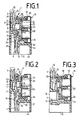
- the terminal block 1 shown in the figures consists of a strip body made of plastic, an upper part 28 and a lower part 29.
- a surge arrester magazine 10 which can be inserted from above is arranged on the side of the terminal block 1.
- insulation displacement contacts 4 are mounted, which are provided for connecting insulated cable wires, not shown, or paper-insulated cable wires.
- the insulation displacement contacts 4 consist in a known manner of a metallic material and are provided with a contact slot 30 into which an insulated cable core is pressed by means of a tool, not shown. When the cable core is pressed into the contact slot 30, the insulation of the cable core is cut through and a contact connection is established between the conductive core of the cable core and the insulation displacement contact.
- insulation displacement contacts 4 are arranged one behind the other in a first row 12.
- the side-by-side insulation displacement contacts 4 are separated from one another by clamping webs 31, as shown in FIG. 4.
- a second row 13 of insulation displacement contacts 4 is arranged on the opposite side.
- the first row 12 of insulation displacement contacts 4 is arranged on the upper side 14 and the second row 13 of insulation displacement contacts 4 on the underside 15 of the terminal strip 1.
- Each insulation displacement contact 4 of the first row 12 is connected to an insulation displacement contact 4 of the second row 13 via a connecting element 3, whereby the cable wires connected to these insulation displacement contacts 4 are also connected to one another.
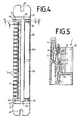
- the connecting element 3 is formed in two parts.
- the connecting element 3 here has two abutting contact springs 6, 7, which form a separation point 8.
- the terminal block 1 is thus designed as a partition bar 2.
- the contact spring 7 of the connecting element 3 is connected to the insulation displacement contact 4 of the second row, the contact end 32 of the contact spring 7 being inserted into a slot 9 in the terminal strip 1 and thus being held immovably.
- the contact spring 6 is formed with the insulation displacement contact 4 of the first row 12 as a one-piece U-shaped isolating contact 45, the contact spring 6 resiliently abutting the contact spring 7 and forming a disconnection point 8. Aligned with this separation point 8, an opening 33 is formed in the terminal block 1, through which an unillustrated plug can be inserted between the contact springs 6, 7 for testing or disconnection.
- the insulation displacement contact 4 of the second row 13 is bent to the front 16 of the terminal block 1 by 90 °, so that the wiring of the cable wires from the front 16 is possible.
- a connector 1 is used in particular where the connector 1 is attached to a flat surface or where the underside 15 of the connector 1 is not accessible.
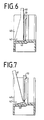
- a receiving chamber 35 for the surge arrester magazine 10 is formed on the side of a housing 34.
- This receiving chamber 35 is provided with a receiving groove 27, which runs parallel to the first row 12 of insulation displacement contacts 4 and into which the surge arrester magazine 10 is inserted.
- the surge arrester magazine 10 has two projections 36 which protrude from the front ends.
- the lower side 37 of the surge arrester magazine 10 lies on the housing bottom 38 of the receiving chambers 35.
- the surge arrester magazine 10 contains a plurality of surge arresters 20, which are arranged in two parallel rows. Each surge arrester 20 is assigned to a pair of insulation displacement contacts 4 on the top and bottom sides 14, 15. The electrical connection to the insulation displacement contacts 4 takes place via contact tongues 11, which are mounted in the surge arrester magazine 10 and are S-shaped. One end 22 of the S-shaped contact tongue 11 serves as a contact surface 19 for one pole side 24 of the surge arrester 20. The other end of the S-shaped contact tongue 11 protrudes from the housing 18 of the surge arrester magazine 10 and is between a clamping contact 5 and the connecting element 3 inserted. The clamping contact 5 is hook-shaped and formed with the connecting element 3 as a one-piece element.
- the earth plate 26, 26a is designed as a U-shaped metal bracket and, as is shown in particular in FIG. 4, consists of two partial plates which are pushed onto the surge arrester magazine 10 from the front side. Sheet flaps 39 are bent on the end faces of the earth plate 26, 26a and are connected to an earth connection (not shown). The side walls 44 of the earth plate 26, 26 a are bent, as a result of which the earth plate 26, 26 a is held on the housing 18 of the surge arrester magazine 10. In the span voltage case, the overvoltage, which flows through the contact tongue 11 through the surge arrester 20, is derived via the earth plate 26, 26a and the earth connection.
- the terminal block 1 can in particular be installed in a terminal block (not shown) or in an end closure.
- the terminal block 1 is fastened to a frame or on a mounting plate by screws which are received in the lateral slots 47 of the terminal block 1.
- Up to twenty connection strips 1 can be arranged within a terminal block.
Applications Claiming Priority (2)
| Application Number | Priority Date | Filing Date | Title |
|---|---|---|---|
| DE3917270 | 1989-05-23 | ||
| DE3917270A DE3917270C2 (de) | 1989-05-23 | 1989-05-23 | Anschlußleiste mit Überspannungsschutz |
Publications (3)
| Publication Number | Publication Date |
|---|---|
| EP0399628A2 true EP0399628A2 (fr) | 1990-11-28 |
| EP0399628A3 EP0399628A3 (fr) | 1992-12-23 |
| EP0399628B1 EP0399628B1 (fr) | 1995-06-07 |
Family
ID=6381501
Family Applications (1)
| Application Number | Title | Priority Date | Filing Date |
|---|---|---|---|
| EP90250072A Expired - Lifetime EP0399628B1 (fr) | 1989-05-23 | 1990-03-16 | Bloc de connexion avec protection contre la surtension |
Country Status (11)
| Country | Link |
|---|---|
| US (1) | US5086368A (fr) |
| EP (1) | EP0399628B1 (fr) |
| JP (1) | JPH0656776B2 (fr) |
| AT (1) | ATE123596T1 (fr) |
| AU (1) | AU630445B2 (fr) |
| CA (1) | CA2017173C (fr) |
| DE (2) | DE3917270C2 (fr) |
| DK (1) | DK0399628T3 (fr) |
| ES (1) | ES2072971T3 (fr) |
| TR (1) | TR25999A (fr) |
| ZA (1) | ZA903932B (fr) |
Cited By (7)
| Publication number | Priority date | Publication date | Assignee | Title |
|---|---|---|---|---|
| WO1992015129A1 (fr) * | 1991-02-25 | 1992-09-03 | N.V. Raychem S.A. | Connector avec protection electrique |
| DE9404393U1 (de) * | 1994-03-16 | 1994-05-11 | Felten & Guilleaume Energie | Überspannungsableiterstecker |
| EP0667650A2 (fr) * | 1994-02-15 | 1995-08-16 | KRONE Aktiengesellschaft | Système de connexion modulaire |
| EP0852827A1 (fr) * | 1995-09-29 | 1998-07-15 | Reltec Corporation | Ensemble bloc de connexion modulaire |
| EP1588457A2 (fr) * | 2002-12-20 | 2005-10-26 | Porta Systems Corporation | Module connecteur |
| WO2012136322A1 (fr) * | 2011-04-05 | 2012-10-11 | Adc Gmbh | Module de répartition de connexions |
| US9780463B2 (en) | 2014-03-13 | 2017-10-03 | Dehn + Söhne Gmbh + Co. Kg | Surge protection device with at least one surge protection unit |
Families Citing this family (31)
| Publication number | Priority date | Publication date | Assignee | Title |
|---|---|---|---|---|
| ATE117132T1 (de) * | 1990-03-13 | 1995-01-15 | Krone Ag | Anschlussleiste für die fernmelde- und datentechnik. |
| US5557250A (en) * | 1991-10-11 | 1996-09-17 | Raychem Corporation | Telecommunications terminal block |
| US6302723B1 (en) | 1991-10-11 | 2001-10-16 | Tyco Electronics Corporation | Telecommunications terminal block |
| US5423694A (en) * | 1993-04-12 | 1995-06-13 | Raychem Corporation | Telecommunications terminal block |
| US5742223A (en) | 1995-12-07 | 1998-04-21 | Raychem Corporation | Laminar non-linear device with magnetically aligned particles |
| DE19608517C2 (de) * | 1996-03-05 | 2000-11-09 | Quante Ag | Anschlußmodul für die Telekommunikationstechnik |
| GB2320144B (en) * | 1996-12-05 | 2000-10-25 | Egerton A C Ltd | Telecommunications apparatus |
| DE19711128C1 (de) * | 1997-03-10 | 1998-07-30 | Krone Ag | Verteilerleiste für die Telekommunikations- und Datentechnik |
| DE19816678C1 (de) * | 1998-04-15 | 2000-01-20 | Quante Ag | Anschlußleiste der Telekommunikationstechnik |
| US6074257A (en) * | 1998-10-06 | 2000-06-13 | Porta Systems Corp. | Electrical connection strip with pivoting conductor guide |
| US6166894A (en) * | 1999-03-15 | 2000-12-26 | Lucent Technologies Inc. | PCB based protector cartridge |
| DE10029649C9 (de) | 2000-06-15 | 2008-02-07 | Adc Gmbh | Verteileranschlußmodul für die Telekommunikations- und Datentechnik |
| KR100482823B1 (ko) * | 2002-11-22 | 2005-04-14 | 오영석 | 발레 타이즈 |
| US6994582B1 (en) * | 2002-12-20 | 2006-02-07 | Porta Systems Corporation | Connector module |
| DE102004061681B4 (de) * | 2004-12-22 | 2006-10-26 | Adc Gmbh | Kabelsteckverbinder für Leiterplatten |
| US8064182B2 (en) | 2007-02-28 | 2011-11-22 | Adc Telecommunications, Inc. | Overvoltage protection plug |
| DE102007026102B3 (de) * | 2007-06-05 | 2008-11-13 | Adc Gmbh | Steckverbinder für Leiterplatten |
| DE102007026094B4 (de) * | 2007-06-05 | 2023-05-11 | Tyco Electronics Services Gmbh | Kontaktelement für einen Steckverbinder für Leiterplatten |
| DE102007026097B4 (de) * | 2007-06-05 | 2023-05-11 | Tyco Electronics Services Gmbh | Steckverbinder für Leiterplatten |
| DE102007026096A1 (de) | 2007-06-05 | 2008-12-11 | Adc Gmbh | Aderanschlussmodul |
| DE102007026095A1 (de) | 2007-06-05 | 2008-12-11 | Adc Gmbh | Erdkamm, insbesondere für einen Steckverbinder für Leiterplatten |
| DE102008013317B4 (de) * | 2008-03-10 | 2010-10-14 | Adc Gmbh | Verfahren zur Herstellung einer Aderanschlussleiste mit Gelfüllung |
| US8179655B2 (en) | 2008-03-28 | 2012-05-15 | Pulse Electronics, Inc. | Surge protection apparatus and methods |
| US7946863B2 (en) * | 2008-04-25 | 2011-05-24 | Adc Telecommunications, Inc. | Circuit protection block |
| US8411404B2 (en) * | 2008-05-27 | 2013-04-02 | Adc Telecommunications, Inc. | Overvoltage protection plug |
| DE102009024330A1 (de) * | 2009-06-09 | 2010-12-16 | Adc Gmbh | Anschlussleiste |
| US9069011B2 (en) * | 2009-09-11 | 2015-06-30 | Exelon Generation Company, Llc | Electrical terminal test point and methods of use |
| DE102011101201B4 (de) * | 2011-05-11 | 2019-12-05 | Tyco Electronics Services Gmbh | Verteileranschlussmodul und Verfahren zur Beschaltung eines Verteileranschlussmoduls |
| US11101633B2 (en) | 2015-10-16 | 2021-08-24 | Frederick M. Foster | Circuit protection system and method |
| CN108292836B (zh) | 2015-10-16 | 2020-11-17 | 弗雷德里克·M·福斯特 | 以太网供电PoE线缆介质通信电路保护系统和方法 |
| CN115424796B (zh) * | 2022-08-31 | 2024-01-30 | 国网新疆电力有限公司奎屯供电公司 | 低压电能计量装置更换绝缘隔离装置 |
Citations (5)
| Publication number | Priority date | Publication date | Assignee | Title |
|---|---|---|---|---|
| DE1487518A1 (de) * | 1966-07-22 | 1969-04-30 | Telefunken Patent | Loetanschlussleiste fuer Fernmelde-,insbesondere Fernsprechanlagen |
| DE1911483A1 (de) * | 1969-03-06 | 1970-09-24 | Krone Kg | Anschlussstreifen fuer Fernmeldeanlagen |
| DE2201504B1 (de) * | 1972-01-13 | 1973-02-15 | Krone Gmbh | Anschlussleiste mit UEberspannungsschutzvorrichtung |
| FR2529393A1 (fr) * | 1982-06-25 | 1983-12-30 | Carpano & Pons | Boitier de protection pour bloc de raccordement dans un repartiteur de telecommunication |
| US4741711A (en) * | 1985-06-03 | 1988-05-03 | Adc Telecommunications, Inc. | Modular distribution frame including protector modules adapted for break access testing |
Family Cites Families (11)
| Publication number | Priority date | Publication date | Assignee | Title |
|---|---|---|---|---|
| DE2811812C2 (de) * | 1978-03-16 | 1984-04-12 | Krone Gmbh, 1000 Berlin | Kabelendeinrichtung der Fernmeldelinientechnik |
| CA1086389A (fr) * | 1978-11-24 | 1980-09-23 | Northern Telecom Limited | Bloc d'interconnexion de deux ensembles de fils electriques |
| US4313147A (en) * | 1978-12-06 | 1982-01-26 | Kabushiki Kaisha Sankosah | Protective device for communication system |
| JPS58176392U (ja) * | 1982-05-20 | 1983-11-25 | 株式会社サンコ−シャ | アレスタ保持装置 |
| DK67084A (da) * | 1983-03-29 | 1984-09-30 | Siemens Ag | Fordelerliste med et antal dobbelttilslutningsklemmer, som tillader afisoleringsfri tilslutning af elektriske ledere |
| DE3412468A1 (de) * | 1984-04-03 | 1985-10-10 | Siemens AG, 1000 Berlin und 8000 München | Verteilerleiste mit einer mehrzahl von den abisolierfreien anschluss elektrischer leiter gestattenden doppelanschlussklemmen |
| DE3509523C3 (de) * | 1985-03-16 | 1996-07-04 | Quante Ag | Kabelabschlußeinheit |
| JPS62120278U (fr) * | 1986-01-21 | 1987-07-30 | ||
| JPS6328263U (fr) * | 1986-08-11 | 1988-02-24 | ||
| DE3726741C1 (de) * | 1987-08-07 | 1988-09-01 | Krone Ag | Anschlussleiste der Fernmeldetechnik |
| US4901190A (en) * | 1988-03-25 | 1990-02-13 | Siemens Aktiengesellschaft | Distribution arrangement for telecommunication apparatus |
-
1989
- 1989-05-23 DE DE3917270A patent/DE3917270C2/de not_active Expired - Fee Related
-
1990
- 1990-03-16 DK DK90250072.7T patent/DK0399628T3/da active
- 1990-03-16 DE DE59009198T patent/DE59009198D1/de not_active Expired - Fee Related
- 1990-03-16 EP EP90250072A patent/EP0399628B1/fr not_active Expired - Lifetime
- 1990-03-16 ES ES90250072T patent/ES2072971T3/es not_active Expired - Lifetime
- 1990-03-16 AT AT90250072T patent/ATE123596T1/de active
- 1990-04-02 JP JP2085068A patent/JPH0656776B2/ja not_active Expired - Lifetime
- 1990-04-23 US US07/512,808 patent/US5086368A/en not_active Expired - Fee Related
- 1990-05-04 TR TR90/0410A patent/TR25999A/xx unknown
- 1990-05-15 AU AU54984/90A patent/AU630445B2/en not_active Ceased
- 1990-05-18 CA CA002017173A patent/CA2017173C/fr not_active Expired - Fee Related
- 1990-05-22 ZA ZA903932A patent/ZA903932B/xx unknown
Patent Citations (6)
| Publication number | Priority date | Publication date | Assignee | Title |
|---|---|---|---|---|
| DE1487518A1 (de) * | 1966-07-22 | 1969-04-30 | Telefunken Patent | Loetanschlussleiste fuer Fernmelde-,insbesondere Fernsprechanlagen |
| DE1911483A1 (de) * | 1969-03-06 | 1970-09-24 | Krone Kg | Anschlussstreifen fuer Fernmeldeanlagen |
| DE2201504B1 (de) * | 1972-01-13 | 1973-02-15 | Krone Gmbh | Anschlussleiste mit UEberspannungsschutzvorrichtung |
| FR2529393A1 (fr) * | 1982-06-25 | 1983-12-30 | Carpano & Pons | Boitier de protection pour bloc de raccordement dans un repartiteur de telecommunication |
| US4741711A (en) * | 1985-06-03 | 1988-05-03 | Adc Telecommunications, Inc. | Modular distribution frame including protector modules adapted for break access testing |
| US4741711B1 (fr) * | 1985-06-03 | 1991-07-30 | Adc Telecommunications Inc |
Cited By (11)
| Publication number | Priority date | Publication date | Assignee | Title |
|---|---|---|---|---|
| WO1992015129A1 (fr) * | 1991-02-25 | 1992-09-03 | N.V. Raychem S.A. | Connector avec protection electrique |
| US5435747A (en) * | 1991-02-25 | 1995-07-25 | N.V. Raychem S.A. | Electrically-protected connector |
| EP0667650A2 (fr) * | 1994-02-15 | 1995-08-16 | KRONE Aktiengesellschaft | Système de connexion modulaire |
| EP0667650A3 (fr) * | 1994-02-15 | 1997-01-29 | Krone Ag | Système de connexion modulaire. |
| DE9404393U1 (de) * | 1994-03-16 | 1994-05-11 | Felten & Guilleaume Energie | Überspannungsableiterstecker |
| EP0852827A1 (fr) * | 1995-09-29 | 1998-07-15 | Reltec Corporation | Ensemble bloc de connexion modulaire |
| EP0852827A4 (fr) * | 1995-09-29 | 1998-12-02 | Reltec Corp | Ensemble bloc de connexion modulaire |
| EP1588457A2 (fr) * | 2002-12-20 | 2005-10-26 | Porta Systems Corporation | Module connecteur |
| EP1588457A4 (fr) * | 2002-12-20 | 2007-08-29 | Porta Systems Corp | Module connecteur |
| WO2012136322A1 (fr) * | 2011-04-05 | 2012-10-11 | Adc Gmbh | Module de répartition de connexions |
| US9780463B2 (en) | 2014-03-13 | 2017-10-03 | Dehn + Söhne Gmbh + Co. Kg | Surge protection device with at least one surge protection unit |
Also Published As
| Publication number | Publication date |
|---|---|
| DE59009198D1 (de) | 1995-07-13 |
| DE3917270A1 (de) | 1990-11-29 |
| AU5498490A (en) | 1990-11-29 |
| AU630445B2 (en) | 1992-10-29 |
| ZA903932B (en) | 1991-03-27 |
| JPH0317972A (ja) | 1991-01-25 |
| EP0399628A3 (fr) | 1992-12-23 |
| ATE123596T1 (de) | 1995-06-15 |
| CA2017173C (fr) | 1995-07-18 |
| DK0399628T3 (da) | 1995-08-14 |
| DE3917270C2 (de) | 1997-10-23 |
| US5086368A (en) | 1992-02-04 |
| CA2017173A1 (fr) | 1990-11-23 |
| EP0399628B1 (fr) | 1995-06-07 |
| ES2072971T3 (es) | 1995-08-01 |
| JPH0656776B2 (ja) | 1994-07-27 |
| TR25999A (tr) | 1993-11-01 |
Similar Documents
| Publication | Publication Date | Title |
|---|---|---|
| EP0399628B1 (fr) | Bloc de connexion avec protection contre la surtension | |
| EP0645841B1 (fr) | Bornes pour montage en ligne | |
| EP0446572B1 (fr) | Bloc de connexion pour technique des télécommunications et de l'informatique | |
| EP0302814B1 (fr) | Barrette de raccordement pour la technique des télécommunications | |
| DE3710896C2 (fr) | ||
| EP0272200B1 (fr) | Bloc de connexion pour les télécommunications | |
| DE3614592C1 (de) | Anschlussleiste fuer Kabeladern,insbesondere von Fernsprechkabeln | |
| DE2736664C2 (de) | Elektrische Anschluß- und/oder Verbindungsklemme, insbesondere Reihenklemme | |
| DE2645325A1 (de) | Eingangsverbinder fuer telefonvermittlungen | |
| EP0338187A2 (fr) | Fiche de protection pour boîters d'interuption ou de disjonction | |
| DE19617114C2 (de) | Erdungsmodul | |
| DE10003266C2 (de) | Stromkreisunterbrechereinrichtung | |
| EP0477664B1 (fr) | Insert de protection pour réglette à bornes installée dans un équipement de télécommunication, en particulier dans un poste annexe téléphonique | |
| EP0180000B1 (fr) | Dispositif à coupure comportant une pluralité de bornes à connexion sans dénudage de conducteurs électriques | |
| DE2712723C2 (de) | Elektrischer Verteiler | |
| DE2642779C2 (de) | Mehrpoliger Rangierstecker | |
| DE2720220A1 (de) | Sicherungsleiste zur halterung elektrischer sicherungen | |
| DE3407991C2 (fr) | ||
| DE2621101C3 (de) | Überspannungsableitervorrichtung für Kabelabschlußgeräte der Fernmeldelinientechnik | |
| EP0667650B1 (fr) | Système de connexion modulaire | |
| EP0960534A1 (fr) | Dispositif pour le reglage de la position de contact des points de contacts a fiches d'un composant d'un distributeur | |
| DE3625422C2 (fr) | ||
| DE10146503A1 (de) | Elektrische Installationsverteilung | |
| DD297285A5 (de) | Verteilerleiste fuer eine telekommunikationsanlage | |
| EP0413978A2 (fr) | Dispositif de protection pour un distributeur dans une installation de télécommunication |
Legal Events
| Date | Code | Title | Description |
|---|---|---|---|
| PUAI | Public reference made under article 153(3) epc to a published international application that has entered the european phase |
Free format text: ORIGINAL CODE: 0009012 |
|
| AK | Designated contracting states |
Kind code of ref document: A2 Designated state(s): AT BE CH DE DK ES FR GB GR IT LI LU NL SE |
|
| PUAL | Search report despatched |
Free format text: ORIGINAL CODE: 0009013 |
|
| AK | Designated contracting states |
Kind code of ref document: A3 Designated state(s): AT BE CH DE DK ES FR GB GR IT LI LU NL SE |
|
| 17P | Request for examination filed |
Effective date: 19921112 |
|
| 17Q | First examination report despatched |
Effective date: 19940704 |
|
| GRAA | (expected) grant |
Free format text: ORIGINAL CODE: 0009210 |
|
| AK | Designated contracting states |
Kind code of ref document: B1 Designated state(s): AT BE CH DE DK ES FR GB GR IT LI LU NL SE |
|
| REF | Corresponds to: |
Ref document number: 123596 Country of ref document: AT Date of ref document: 19950615 Kind code of ref document: T |
|
| ITF | It: translation for a ep patent filed |
Owner name: JACOBACCI & PERANI S.P.A. |
|
| ET | Fr: translation filed | ||
| GBT | Gb: translation of ep patent filed (gb section 77(6)(a)/1977) |
Effective date: 19950605 |
|
| REF | Corresponds to: |
Ref document number: 59009198 Country of ref document: DE Date of ref document: 19950713 |
|
| REG | Reference to a national code |
Ref country code: ES Ref legal event code: FG2A Ref document number: 2072971 Country of ref document: ES Kind code of ref document: T3 |
|
| REG | Reference to a national code |
Ref country code: DK Ref legal event code: T3 |
|
| REG | Reference to a national code |
Ref country code: GR Ref legal event code: FG4A Free format text: 3016392 |
|
| PG25 | Lapsed in a contracting state [announced via postgrant information from national office to epo] |
Ref country code: ES Free format text: LAPSE BECAUSE OF EXPIRATION OF PROTECTION Effective date: 19960318 |
|
| PLBE | No opposition filed within time limit |
Free format text: ORIGINAL CODE: 0009261 |
|
| STAA | Information on the status of an ep patent application or granted ep patent |
Free format text: STATUS: NO OPPOSITION FILED WITHIN TIME LIMIT |
|
| 26N | No opposition filed | ||
| PGFP | Annual fee paid to national office [announced via postgrant information from national office to epo] |
Ref country code: DE Payment date: 19990406 Year of fee payment: 10 |
|
| REG | Reference to a national code |
Ref country code: ES Ref legal event code: FD2A Effective date: 19990601 |
|
| PGFP | Annual fee paid to national office [announced via postgrant information from national office to epo] |
Ref country code: DK Payment date: 20000322 Year of fee payment: 11 |
|
| PG25 | Lapsed in a contracting state [announced via postgrant information from national office to epo] |
Ref country code: DK Free format text: LAPSE BECAUSE OF THE APPLICANT RENOUNCES Effective date: 20000502 |
|
| PG25 | Lapsed in a contracting state [announced via postgrant information from national office to epo] |
Ref country code: DE Free format text: LAPSE BECAUSE OF NON-PAYMENT OF DUE FEES Effective date: 20010103 |
|
| PGFP | Annual fee paid to national office [announced via postgrant information from national office to epo] |
Ref country code: GB Payment date: 20010301 Year of fee payment: 12 |
|
| PGFP | Annual fee paid to national office [announced via postgrant information from national office to epo] |
Ref country code: AT Payment date: 20010316 Year of fee payment: 12 |
|
| PGFP | Annual fee paid to national office [announced via postgrant information from national office to epo] |
Ref country code: SE Payment date: 20010321 Year of fee payment: 12 Ref country code: BE Payment date: 20010321 Year of fee payment: 12 |
|
| PGFP | Annual fee paid to national office [announced via postgrant information from national office to epo] |
Ref country code: NL Payment date: 20010322 Year of fee payment: 12 |
|
| PGFP | Annual fee paid to national office [announced via postgrant information from national office to epo] |
Ref country code: FR Payment date: 20010323 Year of fee payment: 12 Ref country code: CH Payment date: 20010323 Year of fee payment: 12 |
|
| PGFP | Annual fee paid to national office [announced via postgrant information from national office to epo] |
Ref country code: LU Payment date: 20010326 Year of fee payment: 12 |
|
| PGFP | Annual fee paid to national office [announced via postgrant information from national office to epo] |
Ref country code: GR Payment date: 20010329 Year of fee payment: 12 |
|
| NLS | Nl: assignments of ep-patents |
Owner name: KRONE GMBH |
|
| REG | Reference to a national code |
Ref country code: GB Ref legal event code: IF02 |
|
| PG25 | Lapsed in a contracting state [announced via postgrant information from national office to epo] |
Ref country code: LU Free format text: LAPSE BECAUSE OF NON-PAYMENT OF DUE FEES Effective date: 20020316 Ref country code: GB Free format text: LAPSE BECAUSE OF NON-PAYMENT OF DUE FEES Effective date: 20020316 Ref country code: AT Free format text: LAPSE BECAUSE OF NON-PAYMENT OF DUE FEES Effective date: 20020316 |
|
| PG25 | Lapsed in a contracting state [announced via postgrant information from national office to epo] |
Ref country code: SE Free format text: LAPSE BECAUSE OF NON-PAYMENT OF DUE FEES Effective date: 20020317 |
|
| PG25 | Lapsed in a contracting state [announced via postgrant information from national office to epo] |
Ref country code: LI Free format text: LAPSE BECAUSE OF NON-PAYMENT OF DUE FEES Effective date: 20020331 Ref country code: CH Free format text: LAPSE BECAUSE OF NON-PAYMENT OF DUE FEES Effective date: 20020331 Ref country code: BE Free format text: LAPSE BECAUSE OF NON-PAYMENT OF DUE FEES Effective date: 20020331 |
|
| BERE | Be: lapsed |
Owner name: *KRONE A.G. Effective date: 20020331 |
|
| PG25 | Lapsed in a contracting state [announced via postgrant information from national office to epo] |
Ref country code: NL Free format text: LAPSE BECAUSE OF NON-PAYMENT OF DUE FEES Effective date: 20021001 |
|
| PG25 | Lapsed in a contracting state [announced via postgrant information from national office to epo] |
Ref country code: GR Free format text: LAPSE BECAUSE OF NON-PAYMENT OF DUE FEES Effective date: 20021007 |
|
| EUG | Se: european patent has lapsed |
Ref document number: 90250072.7 |
|
| GBPC | Gb: european patent ceased through non-payment of renewal fee |
Effective date: 20020316 |
|
| REG | Reference to a national code |
Ref country code: CH Ref legal event code: PL |
|
| PG25 | Lapsed in a contracting state [announced via postgrant information from national office to epo] |
Ref country code: FR Free format text: LAPSE BECAUSE OF NON-PAYMENT OF DUE FEES Effective date: 20021129 |
|
| NLV4 | Nl: lapsed or anulled due to non-payment of the annual fee |
Effective date: 20021001 |
|
| REG | Reference to a national code |
Ref country code: FR Ref legal event code: ST |
|
| PG25 | Lapsed in a contracting state [announced via postgrant information from national office to epo] |
Ref country code: IT Free format text: LAPSE BECAUSE OF NON-PAYMENT OF DUE FEES Effective date: 20050316 |