EP0399628A2 - Terminal block with surcharge protection - Google Patents
Terminal block with surcharge protection Download PDFInfo
- Publication number
- EP0399628A2 EP0399628A2 EP90250072A EP90250072A EP0399628A2 EP 0399628 A2 EP0399628 A2 EP 0399628A2 EP 90250072 A EP90250072 A EP 90250072A EP 90250072 A EP90250072 A EP 90250072A EP 0399628 A2 EP0399628 A2 EP 0399628A2
- Authority
- EP
- European Patent Office
- Prior art keywords
- terminal block
- insulation displacement
- displacement contacts
- contact
- block according
- Prior art date
- Legal status (The legal status is an assumption and is not a legal conclusion. Google has not performed a legal analysis and makes no representation as to the accuracy of the status listed.)
- Granted
Links
- 238000009413 insulation Methods 0.000 claims abstract description 46
- 238000006073 displacement reaction Methods 0.000 claims abstract description 44
- 238000012360 testing method Methods 0.000 claims abstract description 9
- 210000002105 tongue Anatomy 0.000 claims description 12
- 238000000926 separation method Methods 0.000 claims description 4
- 238000005266 casting Methods 0.000 claims 1
- 239000004020 conductor Substances 0.000 abstract 2
- 238000013459 approach Methods 0.000 description 1
- 238000011990 functional testing Methods 0.000 description 1
- 238000009434 installation Methods 0.000 description 1
- 239000002184 metal Substances 0.000 description 1
- 239000007769 metal material Substances 0.000 description 1
- 238000005192 partition Methods 0.000 description 1
- 238000004382 potting Methods 0.000 description 1
Images
Classifications
-
- H—ELECTRICITY
- H01—ELECTRIC ELEMENTS
- H01R—ELECTRICALLY-CONDUCTIVE CONNECTIONS; STRUCTURAL ASSOCIATIONS OF A PLURALITY OF MUTUALLY-INSULATED ELECTRICAL CONNECTING ELEMENTS; COUPLING DEVICES; CURRENT COLLECTORS
- H01R13/00—Details of coupling devices of the kinds covered by groups H01R12/70 or H01R24/00 - H01R33/00
- H01R13/66—Structural association with built-in electrical component
- H01R13/665—Structural association with built-in electrical component with built-in electronic circuit
- H01R13/6666—Structural association with built-in electrical component with built-in electronic circuit with built-in overvoltage protection
-
- H—ELECTRICITY
- H01—ELECTRIC ELEMENTS
- H01R—ELECTRICALLY-CONDUCTIVE CONNECTIONS; STRUCTURAL ASSOCIATIONS OF A PLURALITY OF MUTUALLY-INSULATED ELECTRICAL CONNECTING ELEMENTS; COUPLING DEVICES; CURRENT COLLECTORS
- H01R4/00—Electrically-conductive connections between two or more conductive members in direct contact, i.e. touching one another; Means for effecting or maintaining such contact; Electrically-conductive connections having two or more spaced connecting locations for conductors and using contact members penetrating insulation
- H01R4/24—Connections using contact members penetrating or cutting insulation or cable strands
- H01R4/2416—Connections using contact members penetrating or cutting insulation or cable strands the contact members having insulation-cutting edges, e.g. of tuning fork type
- H01R4/242—Connections using contact members penetrating or cutting insulation or cable strands the contact members having insulation-cutting edges, e.g. of tuning fork type the contact members being plates having a single slot
- H01R4/2425—Flat plates, e.g. multi-layered flat plates
- H01R4/2429—Flat plates, e.g. multi-layered flat plates mounted in an insulating base
Definitions
- the invention relates to a terminal block with two rows of insulation displacement contacts for connecting insulated cable wires according to the preamble of claim 1.
- a terminal block of this type is previously known from DE-PS 28 11 812.
- This terminal block has two parallel rows of insulation displacement contacts that are used to connect insulated cable wires.
- an overvoltage arrester magazine can be inserted into this terminal block from above.
- Contact tongues arranged on the surge arrester magazine are connected to the insulation displacement contacts.
- the contact tongues are connected to the surge arresters arranged in the housing of the overvoltage magazine.
- a disadvantage of this terminal block is that the insulation displacement contacts are completely covered by the surge arrester magazine and are therefore no longer accessible. Removing the connected cable wires or connecting free contact elements is only possible after pulling out the surge arrester magazine.
- functional tests of the connected cable cores using test plugs can only be carried out after pulling out the surge arrester magazine.
- Another disadvantage is that, due to its structural height, such an arrangement requires a correspondingly large housing for the installation of terminal strips equipped with surge arresters.
- the invention is therefore based on the object to provide a terminal block with overvoltage protection, which allows switching on and off and testing and testing the connected cable wires on the insulation displacement contacts even when overvoltage protection is used, the structural dimensions of the terminal block should be designed so that the terminal block can also be used in flat housing bodies.
- the terminal block is designed such that the two rows of insulation displacement contacts are arranged on different sides of the terminal block and that the surge arrester magazine laterally approximately in the middle between the two rows of cutting -Klemm contacts is arranged. This results in an advantageous, very space-saving arrangement.
- the insulation displacement contacts of both rows are freely accessible even after the surge arrester magazine has been plugged in, so that the cable wires connected there can be switched on and off. It is also possible to test and test the line connection using test equipment.
- the terminal block 1 shown in the figures consists of a strip body made of plastic, an upper part 28 and a lower part 29.
- a surge arrester magazine 10 which can be inserted from above is arranged on the side of the terminal block 1.
- insulation displacement contacts 4 are mounted, which are provided for connecting insulated cable wires, not shown, or paper-insulated cable wires.
- the insulation displacement contacts 4 consist in a known manner of a metallic material and are provided with a contact slot 30 into which an insulated cable core is pressed by means of a tool, not shown. When the cable core is pressed into the contact slot 30, the insulation of the cable core is cut through and a contact connection is established between the conductive core of the cable core and the insulation displacement contact.
- insulation displacement contacts 4 are arranged one behind the other in a first row 12.
- the side-by-side insulation displacement contacts 4 are separated from one another by clamping webs 31, as shown in FIG. 4.
- a second row 13 of insulation displacement contacts 4 is arranged on the opposite side.
- the first row 12 of insulation displacement contacts 4 is arranged on the upper side 14 and the second row 13 of insulation displacement contacts 4 on the underside 15 of the terminal strip 1.
- Each insulation displacement contact 4 of the first row 12 is connected to an insulation displacement contact 4 of the second row 13 via a connecting element 3, whereby the cable wires connected to these insulation displacement contacts 4 are also connected to one another.
- the connecting element 3 is formed in two parts.
- the connecting element 3 here has two abutting contact springs 6, 7, which form a separation point 8.
- the terminal block 1 is thus designed as a partition bar 2.
- the contact spring 7 of the connecting element 3 is connected to the insulation displacement contact 4 of the second row, the contact end 32 of the contact spring 7 being inserted into a slot 9 in the terminal strip 1 and thus being held immovably.
- the contact spring 6 is formed with the insulation displacement contact 4 of the first row 12 as a one-piece U-shaped isolating contact 45, the contact spring 6 resiliently abutting the contact spring 7 and forming a disconnection point 8. Aligned with this separation point 8, an opening 33 is formed in the terminal block 1, through which an unillustrated plug can be inserted between the contact springs 6, 7 for testing or disconnection.
- the insulation displacement contact 4 of the second row 13 is bent to the front 16 of the terminal block 1 by 90 °, so that the wiring of the cable wires from the front 16 is possible.
- a connector 1 is used in particular where the connector 1 is attached to a flat surface or where the underside 15 of the connector 1 is not accessible.
- a receiving chamber 35 for the surge arrester magazine 10 is formed on the side of a housing 34.
- This receiving chamber 35 is provided with a receiving groove 27, which runs parallel to the first row 12 of insulation displacement contacts 4 and into which the surge arrester magazine 10 is inserted.
- the surge arrester magazine 10 has two projections 36 which protrude from the front ends.
- the lower side 37 of the surge arrester magazine 10 lies on the housing bottom 38 of the receiving chambers 35.
- the surge arrester magazine 10 contains a plurality of surge arresters 20, which are arranged in two parallel rows. Each surge arrester 20 is assigned to a pair of insulation displacement contacts 4 on the top and bottom sides 14, 15. The electrical connection to the insulation displacement contacts 4 takes place via contact tongues 11, which are mounted in the surge arrester magazine 10 and are S-shaped. One end 22 of the S-shaped contact tongue 11 serves as a contact surface 19 for one pole side 24 of the surge arrester 20. The other end of the S-shaped contact tongue 11 protrudes from the housing 18 of the surge arrester magazine 10 and is between a clamping contact 5 and the connecting element 3 inserted. The clamping contact 5 is hook-shaped and formed with the connecting element 3 as a one-piece element.
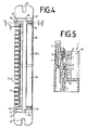
- the earth plate 26, 26a is designed as a U-shaped metal bracket and, as is shown in particular in FIG. 4, consists of two partial plates which are pushed onto the surge arrester magazine 10 from the front side. Sheet flaps 39 are bent on the end faces of the earth plate 26, 26a and are connected to an earth connection (not shown). The side walls 44 of the earth plate 26, 26 a are bent, as a result of which the earth plate 26, 26 a is held on the housing 18 of the surge arrester magazine 10. In the span voltage case, the overvoltage, which flows through the contact tongue 11 through the surge arrester 20, is derived via the earth plate 26, 26a and the earth connection.
- the terminal block 1 can in particular be installed in a terminal block (not shown) or in an end closure.
- the terminal block 1 is fastened to a frame or on a mounting plate by screws which are received in the lateral slots 47 of the terminal block 1.
- Up to twenty connection strips 1 can be arranged within a terminal block.
Landscapes
- Engineering & Computer Science (AREA)
- Microelectronics & Electronic Packaging (AREA)
- Connections Arranged To Contact A Plurality Of Conductors (AREA)
- Emergency Protection Circuit Devices (AREA)
- Details Of Connecting Devices For Male And Female Coupling (AREA)
- Coupling Device And Connection With Printed Circuit (AREA)
- Connections By Means Of Piercing Elements, Nuts, Or Screws (AREA)
- Installation Of Indoor Wiring (AREA)
Abstract
Description
Die Erfindung bezieht sich auf eine Anschlußleiste mit zwei Reihen von Schneid-Klemm-Kontakten zum Anschluß von isolierten Kabeladern gemäß dem Oberbegriff des Anspruches 1.The invention relates to a terminal block with two rows of insulation displacement contacts for connecting insulated cable wires according to the preamble of claim 1.
Eine Anschlußleiste dieser Art ist aus der DE-PS 28 11 812 vorbekannt. Bei dieser Anschlußleiste sind zwei parallele Reihen von Schneid-Klemm-Kontakten vorgesehen, die zum Anschluß von isolierten Kabeladern dienen. Zum Schutz vor Überspannungen dieser Kabeladern ist in diese Anschlußleiste ein Überspannungsableitermagazin von oben einsteckbar. Am Überspannungsableitermagazin angeordnete Kontaktzungen werden hierbei mit den Schneid-Klemm-Kontakten verbunden. Die Kontaktzungen sind mit den im Gehäuse des Überspannungsmagazins angeordneten Überspannungsableitern verbunden. Nachteilig bei dieser Anschlußleiste ist, daß die Schneid-Klemm-Kontakte vollständig durch das Überspannungsableitermagazin abgedeckt und somit nicht mehr zugänglich sind. Ein Entfernen der angeschlossenen Kabeladern bzw. ein Beschalten noch freier Kontaktelemente ist nur nach Ziehen des Überspannungsableitermagazins möglich. Darüber hinaus sind auch Funktionsprüfungen der angeschlossenen Kabeladern mittels Prüfstecker nur nach Ziehen des Überspannungsableitermagazins durchführbar. Ein weitere Nachteil besteht darin, daß eine derartige Anordnung aufgrund seiner baulichen Höhe ein entsprechend großes Gehäuse zum Einbau von mit Überspannungsableitern bestückten Anschlußleisten benötigt.A terminal block of this type is previously known from DE-PS 28 11 812. This terminal block has two parallel rows of insulation displacement contacts that are used to connect insulated cable wires. To protect against overvoltages of these cable cores, an overvoltage arrester magazine can be inserted into this terminal block from above. Contact tongues arranged on the surge arrester magazine are connected to the insulation displacement contacts. The contact tongues are connected to the surge arresters arranged in the housing of the overvoltage magazine. A disadvantage of this terminal block is that the insulation displacement contacts are completely covered by the surge arrester magazine and are therefore no longer accessible. Removing the connected cable wires or connecting free contact elements is only possible after pulling out the surge arrester magazine. In addition, functional tests of the connected cable cores using test plugs can only be carried out after pulling out the surge arrester magazine. Another disadvantage is that, due to its structural height, such an arrangement requires a correspondingly large housing for the installation of terminal strips equipped with surge arresters.
Aus der PS 35 09 523 ist eine weitere Anschlußleiste mit zwei Reihen von Schneid-Klemm-Kontakten und einem mit der Anschlußleiste verbindbaren Überspannungsableitermagazin bekannt. Auch hier wird eine Reihe von Schneid-Klemm-Kontakten vollständig von dem Magazin abgedeckt, so daß die dort angschlossenen Kabeladern nicht zugänglich sind.From
Der Erfindung liegt von daher die Aufgabe zugrunde, eine Anschlußleiste mit einem Überspannungsschutz zu schaffen, welche ein Be- und Entschalten und ein Prüfen und Testen der angeschlossenen Kabeladern an den Schneid-Klemm-Kontakten auch bei eingesetztem Überspannungsschutz zuläßt, wobei die baulichen Abmessungen der Anschlußleiste so ausgebildet sein sollen, daß die Anschlußleiste auch in flache Gehäusekörper einsetzbar ist.The invention is therefore based on the object to provide a terminal block with overvoltage protection, which allows switching on and off and testing and testing the connected cable wires on the insulation displacement contacts even when overvoltage protection is used, the structural dimensions of the terminal block should be designed so that the terminal block can also be used in flat housing bodies.
Die Lösung dieser Aufgabe ergibt sich aus den kennzeichnenden Merkmalen des Patentanspruches 1. Die Anschlußleiste ist derart ausgebildet, daß die beiden Reihen von Schneid-Klemm-Kontakten auf verschiedenen Seiten des Anschlußleiste angeordnet sind und daß das Überspannungsableitermagazin seitlich ungefähr mittig zwischen den beiden Reihen von Schneid-Klemm-Kontakten angeordnet ist. Hieraus ergibt sich eine vorteilhafte, sehr platzsparende Anordnung. Die Schneid-Klemm-Kontakte beider Reihen sind auch nach dem Stecken des Überspannungsableitermagazins frei zugänglich, so daß sowohl ein Be- als auch ein Entschalten der dort angeschlossenen Kabeladern möglich ist. Auch ein Prüfen und Testen der Leitungsverbindung mittels Prüfeinrichtungen ist möglich.The solution to this problem results from the characterizing features of claim 1. The terminal block is designed such that the two rows of insulation displacement contacts are arranged on different sides of the terminal block and that the surge arrester magazine laterally approximately in the middle between the two rows of cutting -Klemm contacts is arranged. This results in an advantageous, very space-saving arrangement. The insulation displacement contacts of both rows are freely accessible even after the surge arrester magazine has been plugged in, so that the cable wires connected there can be switched on and off. It is also possible to test and test the line connection using test equipment.
Weitere vorteilhafte Ausgestaltungen der Erfindung ergeben sich aus den Unteransprüchen. Hierbei wird ins besondere auf die vorteilhafte Anordnung der Kammer- gemäß Anspruch 11 hingewiesen, durch die ein Vergießen der an der unteren Reihe von Schneid-Klemm-Kontakten angeschlossenen Kabeladern möglich ist.Further advantageous embodiments of the invention result from the subclaims. Here is ins particularly pointed out to the advantageous arrangement of the chamber according to
Aus der DE-PS 29 43 578 ist zwar eine Anschlußleiste mit entgegengesetzten Reihen von Anschlußkontakten bekannt, jedoch ist hier kein Überspannungsschutz vorgesehen.From DE-PS 29 43 578 a terminal block with opposite rows of contacts is known, but no surge protection is provided here.
Die Erfindung ist nachfolgend anhand von drei Ausführungsbeispielen von Anschlußleisten näher erläutert.The invention is explained in more detail below using three exemplary embodiments of terminal strips.
Es zeigen:
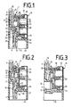
- Fig. 1 einen Querschnitt der Anschlußleiste in einem ersten Ausführungsbeispiel,
- Fig. 2 einen Querschnitt der Anschlußleiste mit einem Trennkontakt in einem zweiten Ausführungsbeispiel,
- Fig. 3 einen Querschnitt der Anschlußleiste in einem dritten Ausführungsbeispiel,
- Fig. 4 die Draufsicht auf die Anschlußleiste,
- Fig. 5 einen Querschnitt gemäß der Linie V-V in Fig. 4,
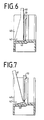
- Fig. 6 einen Schnitt gemäß der Linie VI-VI in Fig. 4 mit einem Schwenkhaken,
- Fig. 7 einen Schnitt gemäß der Linie VI-VI mit gedrehtem Schwenkhaken.
- 1 shows a cross section of the terminal block in a first embodiment,
- 2 shows a cross section of the terminal block with an isolating contact in a second exemplary embodiment,
- 3 shows a cross section of the terminal block in a third exemplary embodiment,
- 4 is a top view of the terminal block,
- 5 shows a cross section along the line VV in FIG. 4,
- 6 shows a section along the line VI-VI in FIG. 4 with a swivel hook,
- Fig. 7 is a section along the line VI-VI with a rotated swivel hook.
Die in den Figuren dargestellte Anschlußleiste 1 besteht aus einem aus Kunststoff hergestellten Leistenkörper, aus einem Oberteil 28 und einem Unterteil 29. Seitlich an der Anschlußleiste 1 ist ein von oben einsteckbares Überspannungsableitermagazin 10 angeordnet. In der Anschlußleiste 1 sind Schneid-Klemm-Kontakte 4 gelagert, die zum Anschluß von nicht dargestellten isolierten Kabeladern oder von papierisolierten Kabeladern vorgesehen sind. Die Schneid-Klemm-Kontakte 4 bestehen in bekannter Weise aus einem metallischem Werkstoff und sind mit einem Kontaktschlitz 30 versehen, in die eine isolierte Kabelader mittels eines nicht dargestellten Werkzeuges eingedrückt wird. Beim Eindrücken der Kabelader in den Kontaktschlitz 30 wird die Isolation der Kabelader durchschnitten und eine Kontaktverbindung zwischen dem leitenden Kern der Kabelader und dem Schneid-Klemm-Kontakt hergestellt. Mehrere Schneid-Klemm-Kontakte 4 sind hintereinander in einer ersten Reihe 12 angeordnet. Die nebeneinander angeordneten Schneid-Klemm-Kontakte 4 sind durch Klemmstege 31 voneinander getrennt, wie es in Fig. 4 dargestellt ist. Zu dieser ersten Reihe 12 von Schneid-Klemm-Kontakten 4 ist auf der entgegengesetzten Seite eine zweite Reihe 13 von Schneid-Klemm-Kontakten 4 angeordnet. Wie es in Fig. 1 dargestellt ist, ist die erste Reihe 12 von Schneid-Klemm-Kontakten 4 an der Oberseite 14 und die zweite Reihe 13 von Schneid-Klemm-Kontakten 4 an der Unterseite 15 der Anschlußleiste 1 angeordnet.The terminal block 1 shown in the figures consists of a strip body made of plastic, an
Jeder Schneid-Klemm-Kontakt 4 der ersten Reihe 12 ist mit einem Schneid-Klemm-Kontakt 4 der zweiten Reihe 13 über ein Verbindungselement 3 verbunden, wodurch auch die an diesen Schneid-Klemm-Kontakten 4 angeschlossenen Kabeladern miteinander verbunden sind.Each
In dem zweiten Ausführungsbeispiel, welches in Fig. 2 dargestellt ist, ist das Verbindungselement 3 zweiteilig ausgebildet. Das Verbindungselement 3 besitzt hier zwei aneinanderstoßende Kontaktfedern 6, 7, die eine Trennstelle 8 bilden. Die Anschlußleiste 1 wird somit als Trennleiste 2 ausgebildet. Die Kontaktfeder 7 des Verbindungselementes 3 ist mit dem Schneid-Klemm-Kontakt 4 der zweiten Reihe verbunden, wobei das Kontaktende 32 der Kontaktfeder 7 in einen Schlitz 9 der Anschlußleiste 1 eingesteckt ist und somit unbeweglich gehalten wird. Die Kontaktfeder 6 ist mit dem Schneid-Klemm-Kontakt 4 der ersten Reihe 12 als einteiliger U-förmiger Trennkontakt 45 ausgebildet, wobei die Kontaktfeder 6 federnd an der Kontaktfeder 7 anliegt und eine Trennstelle 8 bildet. Fluchtend zu dieser Trennstelle 8 ist eine Öffnung 33 in der Anschlußleiste 1 ausgebildet, durch die ein nicht dargestellter Stecker zum Prüfen oder Trennen zwischen die Kontaktfedern 6,7 einsteckbar ist.In the second embodiment, which is shown in Fig. 2, the connecting
In der dritten Ausführungsform ist der Schneid-Klemm-Kontakt 4 der zweiten Reihe 13 zur Vorderseite 16 der Anschlußleiste 1 um 90° abgebogen, so daß das Beschalten der Kabeladern von der Vorderseite 16 möglich ist. Eine derartige Anschlußleiste 1 wird insbesondere dort eingesetzt, wo eine Befestigung der Anschlußleiste 1 auf einer ebenen Unterlage erfolgt bzw. wo die Unterseite 15 der Anschlußleiste 1 nicht zugänglich ist.In the third embodiment, the
Bei den Anschlußleisten 1 aller drei Ausführungsbeispiele ist seitlich an einer Gehäuseseite 34 eine Aufnahmekammer 35 für das Überspannungsableitermagazin 10 ausgebildet. Diese Aufnahmekammer 35 ist mit einer parallel zu der ersten Reihe 12 von Schneid-Klemm-Kontakten 4 verlaufenden Aufnahmenut 27 versehen, in die das Überspannungsableitermagazin 10 eingesteckt ist.In the connection strips 1 of all three exemplary embodiments, a
Das Überspannungsableitermagazin 10 weist hierzu zwei über die stirnseitigen Enden herausstehenden Ansätze 36 auf. Die untere Seite 37 des Überspannungsableitermagazins 10 liegt auf dem Gehäuseboden 38 der Aufnahmekammern 35 auf.For this purpose, the
Das Überspannungsableitermagazin 10 beinhaltet mehrere Überspannungsableiter 20, die in zwei parallelen Reihen angeordnet sind. Jeder Überspannungsableiter 20 ist einem Schneid-Klemm-Kontaktpaar 4 der Ober- und Unterseite 14,15 zugeordnet. Die elektrische Verbindung zu den Schneid-Klemm-Kontakten 4 erfolgt über in dem Überspannungsableitermagazin 10 gelagerten Kontaktzungen 11, die S-förmig ausgebildet sind. Das eine Ende 22 der S-förmigen Kontaktzunge 11 dient als Kontaktfläche 19 für die eine Polseite 24 des Überspannungsableiters 20. Das andere Ende der S-förmigen Kontaktzunge 11 ragt aus dem Gehäuse 18 des Überspannungsableitermagazins 10 heraus und ist zwischen einem Klemmkontakt 5 und dem Verbindungselement 3 eingesteckt. Der Klemmkontakt 5 ist hakenförmig ausgebildet und mit dem Verbindungselement 3 als einteiliges Element ausgebildet. Zwischen der Kontaktfläche 19 der Kontaktzunge 11 und der ersten Polseite 24 des Überspannungsableiters 20 ist eine Klemmfeder 23 angeordnet, die den Überspannungsableiter 20 mit der zweiten Polseite 25 an ein Erdblech 26, 26a andrückt. Das Erdblech 26, 26a ist als U-förmiger Metallbügel ausgebildet und besteht, wie insbesondere in Fig. 4 dargestellt ist, aus zwei Teilblechen, die von der Stirnseite her auf das Überspannungsableitermagazin 10 aufgeschoben sind. An den Stirnseiten des Erdbleches 26, 26a sind Blechlappen 39 abgebogen, die mit einem nicht dargestellten Erdanschluß verbunden sind. Die Seitenwände 44 des Erdbleches 26,26a sind abgebogen, wodurch das Erdblech 26,26a am Gehäuse 18 des Überspannungsableitermagazins 10 festgehalten ist. Im Überspan nungsfall wird die Überspannung, die über die Kontaktzunge 11 durch den Überspannungsableiter 20 fließt, über das Erdblech 26, 26a und den Erdanschluß abgeleitet.The
Zum Herausziehen des Überspannungsableitermagazins 10 aus der Anschlußleiste 1 sind seitlich Aufnahmeschlitze 40 vorgesehen, in die ein insbesonders in den Figuren 6 und 7 dargestellter Hebel 41 aufgenommen ist. Dieser Hebel 41 besitzt einen Haken 43, der unter das Überspannungsableitermagazin 10 gesteckt ist. Durch Drehen des Hebels 41 um einen Drehpunkt 42 kann somit das Überspannungsableitermagazin 10 nach oben ausgeklinkt werden. Die Kontaktverbindung zwischen den Klemmkontakten 5 und den Kontaktzungen 11 wird dadurch gelöst.To pull out the
Die Anschlußleiste 1 ist insbesondere in einem nicht dargestellten Endverzweiger oder in einem Endverschluß einbaubar. Die Anschlußleiste 1 wird durch Schrauben, die in den seitlichen Schlitzen 47 der Anschlußleiste 1 aufgenommen sind, an einem Gestellrahmen oder auf einer Montageplatte befestigt. Innerhalb eines Endverzweigers können bis zu zwanzig Anschlußleisten 1 angeordnet werden.The terminal block 1 can in particular be installed in a terminal block (not shown) or in an end closure. The terminal block 1 is fastened to a frame or on a mounting plate by screws which are received in the
- 1 Anßchlußleiste1 connection strip
- 2 Trennleiste2 dividers
- 3 Verbindungselement3 connecting element
- 4 Schneid-Klemm-Kontakt4 insulation displacement contact
- 5 Klemmkontakt5 terminal contact
- 6,7 Kontaktfedern6.7 contact springs
- 8 Trennstelle8 separation point
- 9 Schlitz9 slot
- 10 Überspannungsableitermagazin10 surge arrester magazine
- 11 Kontaktzunge11 contact tongue
- 12 erste Reihe12 first row
- 13 zweite Reihe13 second row
- 14 Oberseite14 top
- 15 Unterseite15 bottom
- 16 Vorderseite16 front
- 17 Federkontakt17 spring contact
- 18 Gehäuse18 housing
- 19 Kontakfläche19 contact surface
- 20 Überspannungsableiter20 surge arresters
- 21 das eine Ende21 one end
- 22 das andere Ende22 the other end
- 23 Klemmfeder23 clamping spring
- 24,25 Polseite24.25 pole side
- 26,26a Erdblech26.26a earth sheet
- 27 Aufnahmenut27 slot
- 28 Oberteil28 top
- 29 Unterteil29 lower part
- 30 Kontaktschlitz30 contact slot
- 31 Klemmstege31 clamping bars
- 32 Kontaktende32 contact ends
- 33 Öffnung33 opening
- 34 Gehäuseseite34 housing side
- 35 Aufnahmekammer35 receiving chamber
- 36 Ansätze36 approaches
- 37 untere Seite37 lower side
- 38 Gehäuseboden38 case back
- 39 Blechlappen39 sheet rags
- 40 Aufnahmeschlitze40 slots
- 41 Hebel41 levers
- 42 Drehpunkt42 pivot point
- 43 Haken43 hooks
- 44 Seitenwände44 side walls
- 45 Trennkontakt45 isolating contact
- 46 Kammer46 chamber
- 47 Schlitze47 slots
Claims (11)
dadurch gekennzeichnet,
daß die beiden Reihen (12,13) von Schneid-Klemm-Kontakten (4) auf verschiedenen Seiten der Anschlußseite (1) angeordnet sind und daß das Überspannungsableitermagazin (10) seitlich ungefähr mittig zwischen den beiden Reihen (12,13) von Schneid-Klemm-Kontakten (4) angeordnet ist.1. Terminal strip with two rows of insulation displacement contacts for connecting insulated cable cores, in particular cables for telecommunications and data technology, with a surge arrester magazine that can be inserted into the terminal strip and with a connecting element between two insulation displacement contacts of two rows,
characterized by
that the two rows (12, 13) of insulation displacement contacts (4) are arranged on different sides of the connection side (1) and that the surge arrester magazine (10) laterally approximately centrally between the two rows (12, 13) of insulation Clamping contacts (4) is arranged.
dadurch gekennzeichnet,
daß jedes Verbindungselement (3) mit einem Klemmkontakt (5) versehen ist und daß in die Klemmkontakte (5) Kontaktzungen (11) des Überspannungsmagazines (10) einsteckbar sind, welches seitlich an der Anschlußleiste (1) gehalten ist.2. Terminal block according to claim 1,
characterized by
that each connecting element (3) is provided with a clamping contact (5) and that in the clamping contacts (5) contact tongues (11) of the overvoltage magazine (10) can be inserted, which is held on the side of the terminal block (1).
dadurch gekennzeichnet,
daß das Verbindungselement (3) zweiteilig mit aneinanderstoßenden Kontaktfedern (6,7) ausgebildet ist, die eine Trennstelle (8) bilden.3. Terminal block according to claim 1,
characterized by
that the connecting element (3) is formed in two parts with abutting contact springs (6, 7) which form a separation point (8).
dadurch gekennzeichnet,
daß die Schneid-Klemm-Kontakte (4) der ersten Reihe (12) an der Oberseite (14) und die Schneid-Klemm-Kontakte (4) der zweiten Reihe (13) an der Unterseite (15) der Anschlußseite (1) angeordnet sind.4. Terminal block according to claim 1,
characterized by
that the insulation displacement contacts (4) of the first row (12) on the upper side (14) and the insulation displacement contacts (4) of the second row (13) on the underside (15) of the connection side (1) are.
dadurch gekennzeichnet,
daß die Schneid-Klemm-Kontakte (4) der ersten Reihe (12) an der Oberseite (14) und die Schneid-Klemm-Kontakte (4) der zweiten Reihe (13) an der Vorderseite (16) der Anschlußleiste (1) angeordnet sind.5. Terminal block according to claim 1,
characterized by
that the insulation displacement contacts (4) of the first row (12) on the top (14) and the insulation displacement contacts (4) of the second row (13) on the front side (16) of the terminal block (1) are.
dadurch gekennzeichnet,
daß das eine Ende (21) jeder Kontaktzunge (11) aus dem Gehäuse (18) des Überspannungsmagazines (10) zur Kontaktierung mit der Anschlußleiste (1) herausragt und das andere Ende (22) als Kontaktfläche (19) zur Kontaktierung eines Überspannungsableiters (20) ausgebildet ist.6. Terminal block according to claim 1,
characterized by
that one end (21) of each contact tongue (11) protrudes from the housing (18) of the overvoltage magazine (10) for contacting the terminal strip (1) and the other end (22) as a contact surface (19) for contacting a surge arrester (20 ) is trained.
dadurch gekennzeichnet,
daß zwischen der Kontaktfläche (19) jeder Kontaktzunge (11) und der ersten Polseite (24) des Überspannungsableiters (20) eine Klemmfeder (23) angeordnet ist.7. Terminal block according to claim 1,
characterized by
that a clamping spring (23) is arranged between the contact surface (19) of each contact tongue (11) and the first pole side (24) of the surge arrester (20).
dadurch gekennzeichnet,
daß an der zweiten Polseite (25) jedes Überspannungsableiters (20) ein Erdblech (26) angeordnet ist, das über abgebogene Seitenwände (40) festgelegt ist.8. Terminal block according to claims 1 and 7,
characterized by
that on the second pole side (25) of each surge arrester (20) an earth plate (26) is arranged, which is fixed via bent side walls (40).
dadurch gekennzeichnet,
daß am Verbindungselement (3) ein Federkontakt (17) als Prüfabgriff angeordnet ist.9. Terminal block according to claim 1,
characterized by
that a spring contact (17) is arranged as a test tap on the connecting element (3).
dadurch gekennzeichnet,
daß in der Anschlußleiste (1) parallel zu den beiden Reihen (12,13) von Schneid-Klemm-Kontakten (4) eine Aufnahmenut (27) zur Halterung des Überspannungsmagazines (10) vorgesehen ist.10. Terminal block according to claim 1,
characterized by
that in the terminal block (1) parallel to the two rows (12, 13) of insulation displacement contacts (4) there is a receiving groove (27) for holding the overvoltage magazine (10).
dadurch gekennzeichnet,
daß an der Unterseite (15) der Anschlußleiste (1) eine Kammer (46) zum Vergießen der an der zweiten Reihe (13) von Schneid-Klemm-Kontakten (4) angeschlossenen Kabeladern vorgesehen ist.11. Terminal block according to claim 1,
characterized by
that on the underside (15) of the terminal block (1) there is a chamber (46) for casting the cable wires connected to the second row (13) of insulation displacement contacts (4).
Applications Claiming Priority (2)
| Application Number | Priority Date | Filing Date | Title |
|---|---|---|---|
| DE3917270A DE3917270C2 (en) | 1989-05-23 | 1989-05-23 | Terminal block with surge protection |
| DE3917270 | 1989-05-23 |
Publications (3)
| Publication Number | Publication Date |
|---|---|
| EP0399628A2 true EP0399628A2 (en) | 1990-11-28 |
| EP0399628A3 EP0399628A3 (en) | 1992-12-23 |
| EP0399628B1 EP0399628B1 (en) | 1995-06-07 |
Family
ID=6381501
Family Applications (1)
| Application Number | Title | Priority Date | Filing Date |
|---|---|---|---|
| EP90250072A Expired - Lifetime EP0399628B1 (en) | 1989-05-23 | 1990-03-16 | Terminal block with surcharge protection |
Country Status (11)
| Country | Link |
|---|---|
| US (1) | US5086368A (en) |
| EP (1) | EP0399628B1 (en) |
| JP (1) | JPH0656776B2 (en) |
| AT (1) | ATE123596T1 (en) |
| AU (1) | AU630445B2 (en) |
| CA (1) | CA2017173C (en) |
| DE (2) | DE3917270C2 (en) |
| DK (1) | DK0399628T3 (en) |
| ES (1) | ES2072971T3 (en) |
| TR (1) | TR25999A (en) |
| ZA (1) | ZA903932B (en) |
Cited By (7)
| Publication number | Priority date | Publication date | Assignee | Title |
|---|---|---|---|---|
| WO1992015129A1 (en) * | 1991-02-25 | 1992-09-03 | N.V. Raychem S.A. | Electrically-protected connector |
| DE9404393U1 (en) * | 1994-03-16 | 1994-05-11 | Felten & Guilleaume Energietechnik AG, 51063 Köln | Surge arrester plug |
| EP0667650A2 (en) * | 1994-02-15 | 1995-08-16 | KRONE Aktiengesellschaft | Modular connection system |
| EP0852827A1 (en) * | 1995-09-29 | 1998-07-15 | Reltec Corporation | Modular terminal block assembly |
| EP1588457A2 (en) * | 2002-12-20 | 2005-10-26 | Porta Systems Corporation | Connector module |
| WO2012136322A1 (en) * | 2011-04-05 | 2012-10-11 | Adc Gmbh | Distributor connection module |
| US9780463B2 (en) | 2014-03-13 | 2017-10-03 | Dehn + Söhne Gmbh + Co. Kg | Surge protection device with at least one surge protection unit |
Families Citing this family (31)
| Publication number | Priority date | Publication date | Assignee | Title |
|---|---|---|---|---|
| EP0446572B1 (en) * | 1990-03-13 | 1995-01-11 | KRONE Aktiengesellschaft | Telecommunications and data systems engineering terminal block |
| US6302723B1 (en) | 1991-10-11 | 2001-10-16 | Tyco Electronics Corporation | Telecommunications terminal block |
| US5557250A (en) * | 1991-10-11 | 1996-09-17 | Raychem Corporation | Telecommunications terminal block |
| US5423694A (en) * | 1993-04-12 | 1995-06-13 | Raychem Corporation | Telecommunications terminal block |
| US5742223A (en) | 1995-12-07 | 1998-04-21 | Raychem Corporation | Laminar non-linear device with magnetically aligned particles |
| DE19608517C2 (en) * | 1996-03-05 | 2000-11-09 | Quante Ag | Connection module for telecommunications technology |
| GB2320144B (en) * | 1996-12-05 | 2000-10-25 | Egerton A C Ltd | Telecommunications apparatus |
| DE19711128C1 (en) * | 1997-03-10 | 1998-07-30 | Krone Ag | Distribution board for telecommunications and data technology |
| DE19816678C1 (en) * | 1998-04-15 | 2000-01-20 | Quante Ag | Terminal block of telecommunications technology |
| US6074257A (en) * | 1998-10-06 | 2000-06-13 | Porta Systems Corp. | Electrical connection strip with pivoting conductor guide |
| US6166894A (en) * | 1999-03-15 | 2000-12-26 | Lucent Technologies Inc. | PCB based protector cartridge |
| DE10029649C9 (en) * | 2000-06-15 | 2008-02-07 | Adc Gmbh | Distribution terminal module for telecommunications and data technology |
| KR100482823B1 (en) * | 2002-11-22 | 2005-04-14 | 오영석 | ballet tights |
| US6994582B1 (en) * | 2002-12-20 | 2006-02-07 | Porta Systems Corporation | Connector module |
| DE102004061681B4 (en) * | 2004-12-22 | 2006-10-26 | Adc Gmbh | Cable connectors for printed circuit boards |
| US8064182B2 (en) | 2007-02-28 | 2011-11-22 | Adc Telecommunications, Inc. | Overvoltage protection plug |
| DE102007026095A1 (en) | 2007-06-05 | 2008-12-11 | Adc Gmbh | Earth comb, in particular for a connector for printed circuit boards |
| DE102007026097B4 (en) * | 2007-06-05 | 2023-05-11 | Tyco Electronics Services Gmbh | Connectors for printed circuit boards |
| DE102007026102B3 (en) * | 2007-06-05 | 2008-11-13 | Adc Gmbh | Connectors for printed circuit boards |
| DE102007026094B4 (en) | 2007-06-05 | 2023-05-11 | Tyco Electronics Services Gmbh | Contact element for a connector for printed circuit boards |
| DE102007026096A1 (en) | 2007-06-05 | 2008-12-11 | Adc Gmbh | Cable termination module |
| DE102008013317B4 (en) * | 2008-03-10 | 2010-10-14 | Adc Gmbh | Method for producing a wire connection strip with gel filling |
| US8179655B2 (en) | 2008-03-28 | 2012-05-15 | Pulse Electronics, Inc. | Surge protection apparatus and methods |
| US7946863B2 (en) * | 2008-04-25 | 2011-05-24 | Adc Telecommunications, Inc. | Circuit protection block |
| US8411404B2 (en) * | 2008-05-27 | 2013-04-02 | Adc Telecommunications, Inc. | Overvoltage protection plug |
| DE102009024330A1 (en) * | 2009-06-09 | 2010-12-16 | Adc Gmbh | terminal block |
| US9069011B2 (en) * | 2009-09-11 | 2015-06-30 | Exelon Generation Company, Llc | Electrical terminal test point and methods of use |
| DE102011101201B4 (en) * | 2011-05-11 | 2019-12-05 | Tyco Electronics Services Gmbh | Distributor connection module and method for wiring a distributor connection module |
| US11101633B2 (en) | 2015-10-16 | 2021-08-24 | Frederick M. Foster | Circuit protection system and method |
| JP2018532366A (en) | 2015-10-16 | 2018-11-01 | フォスター、フレデリック、エム.FOSTER, Frederick, M. | Circuit protection system and method |
| CN115424796B (en) * | 2022-08-31 | 2024-01-30 | 国网新疆电力有限公司奎屯供电公司 | Insulation isolation device for replacing low-voltage electric energy metering device |
Citations (5)
| Publication number | Priority date | Publication date | Assignee | Title |
|---|---|---|---|---|
| DE1487518A1 (en) * | 1966-07-22 | 1969-04-30 | Telefunken Patent | Solder connection strip for telecommunication, especially telephone systems |
| DE1911483A1 (en) * | 1969-03-06 | 1970-09-24 | Krone Kg | Connection strips for telecommunications systems |
| DE2201504B1 (en) * | 1972-01-13 | 1973-02-15 | Krone Gmbh | Terminal strip with overvoltage protection device |
| FR2529393A1 (en) * | 1982-06-25 | 1983-12-30 | Carpano & Pons | Connector block for telecommunications line-protection device - has channel-section common earthing bar to which parallel devices can be individually connected |
| US4741711A (en) * | 1985-06-03 | 1988-05-03 | Adc Telecommunications, Inc. | Modular distribution frame including protector modules adapted for break access testing |
Family Cites Families (11)
| Publication number | Priority date | Publication date | Assignee | Title |
|---|---|---|---|---|
| DE2811812C2 (en) * | 1978-03-16 | 1984-04-12 | Krone Gmbh, 1000 Berlin | Cable terminal equipment for telecommunications line technology |
| CA1086389A (en) * | 1978-11-24 | 1980-09-23 | Northern Telecom Limited | Block for interconnecting two pluralities of electrical wires |
| US4313147A (en) * | 1978-12-06 | 1982-01-26 | Kabushiki Kaisha Sankosah | Protective device for communication system |
| JPS58176392U (en) * | 1982-05-20 | 1983-11-25 | 株式会社サンコ−シャ | Arrestor retention device |
| DK67084A (en) * | 1983-03-29 | 1984-09-30 | Siemens Ag | DISTRIBUTOR LIST WITH NUMBER OF DOUBLE CONNECTION CLIPS THAT ALLOW ELECTRIC CONNECTOR-FREE CONNECTION FREE |
| DE3412468A1 (en) * | 1984-04-03 | 1985-10-10 | Siemens AG, 1000 Berlin und 8000 München | DISTRIBUTION BOARD WITH A MULTIPLE OF DOUBLE-TERMINAL TERMINALS CONNECTED FROM THE STRIP-FREE CONNECTION |
| DE3509523C3 (en) * | 1985-03-16 | 1996-07-04 | Quante Ag | Cable termination unit |
| JPS62120278U (en) * | 1986-01-21 | 1987-07-30 | ||
| JPS6328263U (en) * | 1986-08-11 | 1988-02-24 | ||
| DE3726741C1 (en) * | 1987-08-07 | 1988-09-01 | Krone Ag | Terminal block of telecommunications technology |
| US4901190A (en) * | 1988-03-25 | 1990-02-13 | Siemens Aktiengesellschaft | Distribution arrangement for telecommunication apparatus |
-
1989
- 1989-05-23 DE DE3917270A patent/DE3917270C2/en not_active Expired - Fee Related
-
1990
- 1990-03-16 AT AT90250072T patent/ATE123596T1/en active
- 1990-03-16 DE DE59009198T patent/DE59009198D1/en not_active Expired - Fee Related
- 1990-03-16 EP EP90250072A patent/EP0399628B1/en not_active Expired - Lifetime
- 1990-03-16 DK DK90250072.7T patent/DK0399628T3/en active
- 1990-03-16 ES ES90250072T patent/ES2072971T3/en not_active Expired - Lifetime
- 1990-04-02 JP JP2085068A patent/JPH0656776B2/en not_active Expired - Lifetime
- 1990-04-23 US US07/512,808 patent/US5086368A/en not_active Expired - Fee Related
- 1990-05-04 TR TR90/0410A patent/TR25999A/en unknown
- 1990-05-15 AU AU54984/90A patent/AU630445B2/en not_active Ceased
- 1990-05-18 CA CA002017173A patent/CA2017173C/en not_active Expired - Fee Related
- 1990-05-22 ZA ZA903932A patent/ZA903932B/en unknown
Patent Citations (6)
| Publication number | Priority date | Publication date | Assignee | Title |
|---|---|---|---|---|
| DE1487518A1 (en) * | 1966-07-22 | 1969-04-30 | Telefunken Patent | Solder connection strip for telecommunication, especially telephone systems |
| DE1911483A1 (en) * | 1969-03-06 | 1970-09-24 | Krone Kg | Connection strips for telecommunications systems |
| DE2201504B1 (en) * | 1972-01-13 | 1973-02-15 | Krone Gmbh | Terminal strip with overvoltage protection device |
| FR2529393A1 (en) * | 1982-06-25 | 1983-12-30 | Carpano & Pons | Connector block for telecommunications line-protection device - has channel-section common earthing bar to which parallel devices can be individually connected |
| US4741711A (en) * | 1985-06-03 | 1988-05-03 | Adc Telecommunications, Inc. | Modular distribution frame including protector modules adapted for break access testing |
| US4741711B1 (en) * | 1985-06-03 | 1991-07-30 | Adc Telecommunications Inc |
Cited By (11)
| Publication number | Priority date | Publication date | Assignee | Title |
|---|---|---|---|---|
| WO1992015129A1 (en) * | 1991-02-25 | 1992-09-03 | N.V. Raychem S.A. | Electrically-protected connector |
| US5435747A (en) * | 1991-02-25 | 1995-07-25 | N.V. Raychem S.A. | Electrically-protected connector |
| EP0667650A2 (en) * | 1994-02-15 | 1995-08-16 | KRONE Aktiengesellschaft | Modular connection system |
| EP0667650A3 (en) * | 1994-02-15 | 1997-01-29 | Krone Ag | Modular connection system. |
| DE9404393U1 (en) * | 1994-03-16 | 1994-05-11 | Felten & Guilleaume Energietechnik AG, 51063 Köln | Surge arrester plug |
| EP0852827A1 (en) * | 1995-09-29 | 1998-07-15 | Reltec Corporation | Modular terminal block assembly |
| EP0852827A4 (en) * | 1995-09-29 | 1998-12-02 | Reltec Corp | Modular terminal block assembly |
| EP1588457A2 (en) * | 2002-12-20 | 2005-10-26 | Porta Systems Corporation | Connector module |
| EP1588457A4 (en) * | 2002-12-20 | 2007-08-29 | Porta Systems Corp | Connector module |
| WO2012136322A1 (en) * | 2011-04-05 | 2012-10-11 | Adc Gmbh | Distributor connection module |
| US9780463B2 (en) | 2014-03-13 | 2017-10-03 | Dehn + Söhne Gmbh + Co. Kg | Surge protection device with at least one surge protection unit |
Also Published As
| Publication number | Publication date |
|---|---|
| EP0399628A3 (en) | 1992-12-23 |
| EP0399628B1 (en) | 1995-06-07 |
| CA2017173A1 (en) | 1990-11-23 |
| US5086368A (en) | 1992-02-04 |
| JPH0317972A (en) | 1991-01-25 |
| ATE123596T1 (en) | 1995-06-15 |
| DE3917270C2 (en) | 1997-10-23 |
| DE3917270A1 (en) | 1990-11-29 |
| JPH0656776B2 (en) | 1994-07-27 |
| AU5498490A (en) | 1990-11-29 |
| CA2017173C (en) | 1995-07-18 |
| ES2072971T3 (en) | 1995-08-01 |
| DK0399628T3 (en) | 1995-08-14 |
| DE59009198D1 (en) | 1995-07-13 |
| AU630445B2 (en) | 1992-10-29 |
| ZA903932B (en) | 1991-03-27 |
| TR25999A (en) | 1993-11-01 |
Similar Documents
| Publication | Publication Date | Title |
|---|---|---|
| EP0399628B1 (en) | Terminal block with surcharge protection | |
| EP0645841B1 (en) | Terminals for side by side mounting | |
| EP0446572B1 (en) | Telecommunications and data systems engineering terminal block | |
| EP0302814B1 (en) | Terminal block for the telecommunication technique | |
| DE3710896C2 (en) | ||
| EP0272200B1 (en) | Connecting block for the telecommunications | |
| DE3614592C1 (en) | Terminal block for cable cores, especially telephone cables | |
| DE2736664C2 (en) | Electrical connection and / or connecting terminal, in particular series terminal | |
| DE2645325A1 (en) | INPUT CONNECTOR FOR TELEPHONE SWITCHES | |
| EP0338187A2 (en) | Safety plug for switching or disconnecting rails | |
| DE19617114C2 (en) | Grounding module | |
| DE10003266C2 (en) | Circuit breaker device | |
| EP0477664B1 (en) | Protector plug for distributor board of telephonic equipments, in particular for private branch exchanges | |
| EP0180000B1 (en) | Cut-over apparatus comprising a plurality of terminals for the stripless connection of electrical conductors | |
| DE2712723C2 (en) | Electrical distributor | |
| DE2642779C2 (en) | Multipole jumper plug | |
| DE3407991C2 (en) | ||
| DE2720220A1 (en) | Fuse panel with double row of contact elements - accommodates one or more cassettes each carrying several fuses engaging pairs of contacts | |
| DE2621101C3 (en) | Surge arrester device for cable termination devices in telecommunications line technology | |
| EP0667650B1 (en) | Modular connection system | |
| EP0960534A1 (en) | Device for regulating the contact position of plug-in contact points of a distribution component | |
| DD297285A5 (en) | Distribution panel for a telecommunication system | |
| DE3625422C2 (en) | ||
| DE10146503A1 (en) | Electrical installation distribution | |
| EP0413978A2 (en) | Protective device for a distributor in a telecommunication installation |
Legal Events
| Date | Code | Title | Description |
|---|---|---|---|
| PUAI | Public reference made under article 153(3) epc to a published international application that has entered the european phase |
Free format text: ORIGINAL CODE: 0009012 |
|
| AK | Designated contracting states |
Kind code of ref document: A2 Designated state(s): AT BE CH DE DK ES FR GB GR IT LI LU NL SE |
|
| PUAL | Search report despatched |
Free format text: ORIGINAL CODE: 0009013 |
|
| AK | Designated contracting states |
Kind code of ref document: A3 Designated state(s): AT BE CH DE DK ES FR GB GR IT LI LU NL SE |
|
| 17P | Request for examination filed |
Effective date: 19921112 |
|
| 17Q | First examination report despatched |
Effective date: 19940704 |
|
| GRAA | (expected) grant |
Free format text: ORIGINAL CODE: 0009210 |
|
| AK | Designated contracting states |
Kind code of ref document: B1 Designated state(s): AT BE CH DE DK ES FR GB GR IT LI LU NL SE |
|
| REF | Corresponds to: |
Ref document number: 123596 Country of ref document: AT Date of ref document: 19950615 Kind code of ref document: T |
|
| ITF | It: translation for a ep patent filed | ||
| ET | Fr: translation filed | ||
| GBT | Gb: translation of ep patent filed (gb section 77(6)(a)/1977) |
Effective date: 19950605 |
|
| REF | Corresponds to: |
Ref document number: 59009198 Country of ref document: DE Date of ref document: 19950713 |
|
| REG | Reference to a national code |
Ref country code: ES Ref legal event code: FG2A Ref document number: 2072971 Country of ref document: ES Kind code of ref document: T3 |
|
| REG | Reference to a national code |
Ref country code: DK Ref legal event code: T3 |
|
| REG | Reference to a national code |
Ref country code: GR Ref legal event code: FG4A Free format text: 3016392 |
|
| PG25 | Lapsed in a contracting state [announced via postgrant information from national office to epo] |
Ref country code: ES Free format text: LAPSE BECAUSE OF EXPIRATION OF PROTECTION Effective date: 19960318 |
|
| PLBE | No opposition filed within time limit |
Free format text: ORIGINAL CODE: 0009261 |
|
| STAA | Information on the status of an ep patent application or granted ep patent |
Free format text: STATUS: NO OPPOSITION FILED WITHIN TIME LIMIT |
|
| 26N | No opposition filed | ||
| PGFP | Annual fee paid to national office [announced via postgrant information from national office to epo] |
Ref country code: DE Payment date: 19990406 Year of fee payment: 10 |
|
| REG | Reference to a national code |
Ref country code: ES Ref legal event code: FD2A Effective date: 19990601 |
|
| PGFP | Annual fee paid to national office [announced via postgrant information from national office to epo] |
Ref country code: DK Payment date: 20000322 Year of fee payment: 11 |
|
| PG25 | Lapsed in a contracting state [announced via postgrant information from national office to epo] |
Ref country code: DK Free format text: LAPSE BECAUSE OF THE APPLICANT RENOUNCES Effective date: 20000502 |
|
| PG25 | Lapsed in a contracting state [announced via postgrant information from national office to epo] |
Ref country code: DE Free format text: LAPSE BECAUSE OF NON-PAYMENT OF DUE FEES Effective date: 20010103 |
|
| PGFP | Annual fee paid to national office [announced via postgrant information from national office to epo] |
Ref country code: GB Payment date: 20010301 Year of fee payment: 12 |
|
| PGFP | Annual fee paid to national office [announced via postgrant information from national office to epo] |
Ref country code: AT Payment date: 20010316 Year of fee payment: 12 |
|
| PGFP | Annual fee paid to national office [announced via postgrant information from national office to epo] |
Ref country code: SE Payment date: 20010321 Year of fee payment: 12 Ref country code: BE Payment date: 20010321 Year of fee payment: 12 |
|
| PGFP | Annual fee paid to national office [announced via postgrant information from national office to epo] |
Ref country code: NL Payment date: 20010322 Year of fee payment: 12 |
|
| PGFP | Annual fee paid to national office [announced via postgrant information from national office to epo] |
Ref country code: FR Payment date: 20010323 Year of fee payment: 12 Ref country code: CH Payment date: 20010323 Year of fee payment: 12 |
|
| PGFP | Annual fee paid to national office [announced via postgrant information from national office to epo] |
Ref country code: LU Payment date: 20010326 Year of fee payment: 12 |
|
| PGFP | Annual fee paid to national office [announced via postgrant information from national office to epo] |
Ref country code: GR Payment date: 20010329 Year of fee payment: 12 |
|
| NLS | Nl: assignments of ep-patents |
Owner name: KRONE GMBH |
|
| REG | Reference to a national code |
Ref country code: GB Ref legal event code: IF02 |
|
| PG25 | Lapsed in a contracting state [announced via postgrant information from national office to epo] |
Ref country code: LU Free format text: LAPSE BECAUSE OF NON-PAYMENT OF DUE FEES Effective date: 20020316 Ref country code: GB Free format text: LAPSE BECAUSE OF NON-PAYMENT OF DUE FEES Effective date: 20020316 Ref country code: AT Free format text: LAPSE BECAUSE OF NON-PAYMENT OF DUE FEES Effective date: 20020316 |
|
| PG25 | Lapsed in a contracting state [announced via postgrant information from national office to epo] |
Ref country code: SE Free format text: LAPSE BECAUSE OF NON-PAYMENT OF DUE FEES Effective date: 20020317 |
|
| PG25 | Lapsed in a contracting state [announced via postgrant information from national office to epo] |
Ref country code: LI Free format text: LAPSE BECAUSE OF NON-PAYMENT OF DUE FEES Effective date: 20020331 Ref country code: CH Free format text: LAPSE BECAUSE OF NON-PAYMENT OF DUE FEES Effective date: 20020331 Ref country code: BE Free format text: LAPSE BECAUSE OF NON-PAYMENT OF DUE FEES Effective date: 20020331 |
|
| BERE | Be: lapsed |
Owner name: *KRONE A.G. Effective date: 20020331 |
|
| PG25 | Lapsed in a contracting state [announced via postgrant information from national office to epo] |
Ref country code: NL Free format text: LAPSE BECAUSE OF NON-PAYMENT OF DUE FEES Effective date: 20021001 |
|
| PG25 | Lapsed in a contracting state [announced via postgrant information from national office to epo] |
Ref country code: GR Free format text: LAPSE BECAUSE OF NON-PAYMENT OF DUE FEES Effective date: 20021007 |
|
| EUG | Se: european patent has lapsed |
Ref document number: 90250072.7 |
|
| GBPC | Gb: european patent ceased through non-payment of renewal fee |
Effective date: 20020316 |
|
| REG | Reference to a national code |
Ref country code: CH Ref legal event code: PL |
|
| PG25 | Lapsed in a contracting state [announced via postgrant information from national office to epo] |
Ref country code: FR Free format text: LAPSE BECAUSE OF NON-PAYMENT OF DUE FEES Effective date: 20021129 |
|
| NLV4 | Nl: lapsed or anulled due to non-payment of the annual fee |
Effective date: 20021001 |
|
| REG | Reference to a national code |
Ref country code: FR Ref legal event code: ST |
|
| PG25 | Lapsed in a contracting state [announced via postgrant information from national office to epo] |
Ref country code: IT Free format text: LAPSE BECAUSE OF NON-PAYMENT OF DUE FEES Effective date: 20050316 |