EP0397201A2 - Elektrophotographisches Gerät - Google Patents
Elektrophotographisches Gerät Download PDFInfo
- Publication number
- EP0397201A2 EP0397201A2 EP90108931A EP90108931A EP0397201A2 EP 0397201 A2 EP0397201 A2 EP 0397201A2 EP 90108931 A EP90108931 A EP 90108931A EP 90108931 A EP90108931 A EP 90108931A EP 0397201 A2 EP0397201 A2 EP 0397201A2
- Authority
- EP
- European Patent Office
- Prior art keywords
- cleaning
- contact
- drum
- ized
- character
- Prior art date
- Legal status (The legal status is an assumption and is not a legal conclusion. Google has not performed a legal analysis and makes no representation as to the accuracy of the status listed.)
- Granted
Links
Images


Classifications
-
- G—PHYSICS
- G03—PHOTOGRAPHY; CINEMATOGRAPHY; ANALOGOUS TECHNIQUES USING WAVES OTHER THAN OPTICAL WAVES; ELECTROGRAPHY; HOLOGRAPHY
- G03G—ELECTROGRAPHY; ELECTROPHOTOGRAPHY; MAGNETOGRAPHY
- G03G21/00—Arrangements not provided for by groups G03G13/00 - G03G19/00, e.g. cleaning, elimination of residual charge
- G03G21/0005—Arrangements not provided for by groups G03G13/00 - G03G19/00, e.g. cleaning, elimination of residual charge for removing solid developer or debris from the electrographic recording medium
- G03G21/0011—Arrangements not provided for by groups G03G13/00 - G03G19/00, e.g. cleaning, elimination of residual charge for removing solid developer or debris from the electrographic recording medium using a blade; Details of cleaning blades, e.g. blade shape, layer forming
- G03G21/0029—Details relating to the blade support
Definitions
- the present invention relates to an electrophotographic apparatus.
- an electrophotographic apparatus comprises a drum-shaped image carrier disposed in an apparatus casing for rotation and an image forming mechanism arranged around the image carrier.
- the image forming mechanism includes a charger for uniformly charging the surface of the image carrier and an exposure unit for applying a laser beam to the charged image carrier surface in accordance with print data or the like, thereby forming an electrostatic latent image on the surface.
- the mechanism further includes a developing device for applying a toner to the image carrier surface with the electrostatic latent image thereon, thereby developing the latent image, a transfer device for transferring the resulting toner image to a paper sheet, and a de-electrifier for de-electrifying the image carrier after transfer. These elements are arranged successively around the image carrier.
- the electrophotographic apparatus is provided with a cleaning system for cleaning the surface of the image carrier after the transfer.
- Conventional cleaning systems include mechanical and magnetic cleaning systems.
- a blade In the mechanical cleaning system, a blade is brought into contact with the surface of the image carrier so that the residual toner is scraped from the image carrier surface by the blade, and the scraped toner is collected into a waste toner receiving portion. Since this system is designed so that the residual toner is scraped off directly by means of the blade, the image carrier can be satisfactorily cleaned for a long period of time. If the blade vibrates or if the pressure of contact between the blade and the image carrier becomes too high during the cleaning operation, however, the surface of the image carrier can be easily damaged. Thus, satisfactory print quality cannot be maintained.
- the magnetic cleaning system which is formed integrally with the developing device, cooperates therewith to effect development and remove the toner remaining on the surface of the image carrier by magnetic force so that the removed toner is recovered in the developing device.
- the control of the magnetic cleaning system is more complicated than that of the mechanical cleaning system, the magnetic system can recover the residual toner for reuse without touching the image carrier. Accordingly, many of modern electrophotographic apparatuses use the magnetic cleaning system.
- the residual toner adheres firmly to the surface of the image carrier, however, it cannot be securely removed if the image carrier surface is cleaned by means of the magnetic cleaning system whose cleaning capacity is lower than that of the mechanical cleaning system. In such a case, the residual toner causes defective printing, such as partial blackening of the printable surface of the paper sheet. If the cleaning capacity of the cleaning system is lowered during use, in particular, defective printing is liable to be caused.
- the cleaning capacity of the magnetic cleaning system cannot be adjusted during the operation of the electrophotographic apparatus. In order to eliminate defective printing caused during the operation of the apparatus, therefore, the operation of must be interrupted to adjust the cleaning system, thereby increasing its cleaning capacity. Accordingly, the printing efficiency is lowered.
- This problem may possibly be solved by previously adjusting the cleaning system to the maximum cleaning capacity before the start of the operation of the apparatus. If this is done, however, lowering of the capacity of the cleaning system will be accelerated, so that the lifetime of the system will be shortened.
- the present invention has been contrived in consideration of these circumstances, and its object is to provide an electrophotographic apparatus capable of stably cleaning an image carrier for a long period of time and preventing the print quality and printing efficiency from lowering.
- an electro photographic apparatus comprises magnetic cleaning means for magnetically cleaning an image carrier and mechanical cleaning means for mechanically cleaning the image carrier.
- the image carrier is cleaned by means of the magnetic cleaning means, and the mechanical cleaning means is optionally actuated to supplement the cleaning capacity of the magnetic one.
- the mechanical cleaning means is immediately actuated to compensate the deficiency in the cleaning effect.
- the electrophotographic apparatus comprises image forming means including an image carrier, for forming an image on a recording medium; magnetic cleaning means for magnetically cleaning the surface of the image carrier; mechanical cleaning means for mechanically cleaning the surface of the image carrier, the mechanical cleaning means including a contact member capable of touching and leaving the surface of the image carrier; and actuating means for optionally bringing the contact member into contact with the surface of the image carrier.
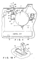
- an electrophotographic apparatus comprises a casing 7 and an image forming mechanism 10 disposed therein.
- the mechanism 10 includes a rotatable photoconductive drum 1 as an image carrier, a charger 2 for uniformly charging the surface of the drum, and an exposure unit 3 for applying a laser beam to the charged drum surface in accordance with print data or the like, thereby forming an electrostatic latent image on the drum surface.
- the mechanism 10 further includes a developing device 4 for applying a toner to the drum surface with the electrostatic latent image thereon, thereby developing the latent image, a transfer device 5 for transferring the resulting toner image to a paper sheet 9, and an eraser 6 for de-electrifying the drum after transfer. These elements are arranged successivesively around the drum.
- the electrophotographic apparatus further comprises a magnetic cleaning system 14 for cleaning the surface of the drum 1.
- the removed toner is recovered in a housing 12 of the developing device 4.
- the electrophotographic apparatus comprises a mechanical cleaning system 20 which is used to supplement the cleaning capacity of the magnetic cleaning system 14.
- the system 20 includes a blade 22, which can touch and leave the surface of the drum 1.
- the cleaning system 20 includes a lever 24 which is rotatable around a pivot 24a in the casing 7, and the blade 22 is fixed to the lower end portion of the lever. As the lever 24 rotates, the blade 22 can move between a contact position where it is in contact with the surface of the drum 1 and an off position where it is kept apart from the drum surface. In the contact position, the blade 22 serves to scrape off the residual toner from the drum surface, and the scraped toner is recovered in a receiving portion 23 defined by a housing 21.
- a tension spring 27 is stretched between the lever 24 and the casing 7, and the lever 24 and the blade 22 are normally kept in the off position shown in Fig. 1.
- the upper end portion of the lever 24 projects to the outside of the casing 7 through an opening 7a in the casing.
- An operating knob 24b is attached to the projecting end of the lever 24.
- the blade 22 can be moved to the contact position by manually rotating the lever 24 in the direction of arrow A, against the urging force of the spring 27, from outside the casing 7.
- the cleaning capacity of the whole electrophotographic apparatus can be improved in accordance with printing results, without interrupting the operation of the apparatus.
- a scale 8 for indicating the shift of the lever 24 is disposed on the outer surface of the casing 7 in the vicinity of the opening 7a.
- the pressure of contact between the blade 22 and the surface of the drum 1 can be easily adjusted by regulating the shift of the lever 24 according to the scale 8.
- the cleaning system 20 includes a solenoid 25 as a drive source for automatically rotating the lever 24.
- the solenoid 25 is excited in response to a signal from the unit 30, the plunger 25a is drawn into the solenoid, so that the lever 24 is rotated in the direction of arrow A against the urging force of the spring 27.
- the blade 22 is brought into contact with the surface of the drum 1, thereby cleaning the drum surface.
- the control unit 30 is constructed by using a CPU, ROM, RAM, control panel, timer, etc., which constitutes a computer circuit in an automatic control device for controlling the operation of the image forming mechanism 10. If a key 31 on the control panel is depressed, the unit 30 excites the solenoid 25, thereby moving the blade 22.
- Programmed in the ROM are various operating modes for automatically intermittently operating the cleaning system 20 at suitable time intervals, e.g., first to third operating modes.
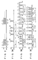
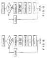
- the control unit 30 drives the mechanical cleaning system 20 for predetermined operating times T0, T1, T2, T3, ... at intervals of predetermined times (rest-times) t0, t1, t2, t3, ..., as shown in Fig. 3A.
- the rest-times and operating times are adjusted to periods of time which allow the residual toner, having failed to be removed by means of the magnetic cleaning system 14, to be scraped off by means of the blade 22 without damaging the surface of the drum 1.
- the rest-times t0, t1, t2, t3, ... are regular, and each rest-time is adjusted to the operation time of the apparatus required for 600 prints.
- the operating times T0, T1, T2, T3, ... are regular, and each operating time is adjusted to the operation time required for two prints.
- the control unit 30 drives the mechanical cleaning system 20 for gradually increasing predetermined operating times T0, T1, T2, T3, ... at the regular intervals of the rest-times t0, t1, t2, t3, ..., as shown in Fig. 3B.
- each rest-time is equivalent to the period of time required for 600 prints
- the operating times T0, T1, T2 and T3 are equivalent to the periods of time required 2, 3, 4 and 5 prints, respectively.
- the cleaning system 20 is driven for the operating time T0 before the passage of the rest-time t0 x 10 after the start of use of the drum 1; T1 before the passage of the rest-time t1 ⁇ 8 thereafter, T2 before the passage of the rest time t2 ⁇ 5 thereafter, and T3 before the passage of the rest-time t3 ⁇ 3 thereafter.
- control unit 30 drives the mechanical cleaning system 20 for the regular operating times T0, T1, T2, T3, ..., equivalent to the period of time required for, e.g., two prints, at gradually reducing rest-times t0, t1, t2, t3, ..., as shown in Fig. 3C.
- the first ten rest-times after the start of use of the drum 1 are t0 (equivalent to the period for 600 prints), second ten rest-times are t1 (equivalent to the period for 400 prints), third ten rest-times are t2 (equivalent to the period for 300 prints), and the last ten rest-times are t3 (equivalent to the period for 200 prints).
- the ROM is programmed to the effect that the cleaning system 20 be driven by the control unit 30 to bring the blade 22 into contact with the surface of the drum 1 for a predetermined time Tr even during a rest-time when the blade 22 is kept off the drum surface, if the key 31 on the control panel is depressed to input an optional command signal.
- the CPU of the control unit 30 excites the solenoid 25 to bring the blade 22 into contact with the drum surface for the predetermined time Tr, as shown in Figs. 3A to 3C, prior to the execution of a supplementary cleaning program based on the operating mode.
- the automatic control device causes the drum 1 to rotate, and drives the charger 2, exposure unit 3, developing device 4, etc. in predetermined steps of procedure, thereby forming a toner image on the surface of the drum 1.
- the toner image is transferred to the fed paper sheet 9 in the transfer device 5, and thereafter, the eraser 6 is driven to de-electrify the residual charge on the drum surface.
- the automatic control device stops driving the charger 2, exposure unit 3, developing device 4, trans fer device 5, etc., and causes the control unit 30 to actuate the magnetic cleaning system 14 while rotating the drum 1.
- the drum 1 is cleaned for the predetermined time t , as shown in Fig. 2, and the mag netic toner remaining on the drum surface is recovered in the housing 12 of the developing device 4.
- printing operation is continuously performed while alternately repeating the image forming cycle and the cleaning cycle.
- control unit 30 actuates the mechanical cleaning system 20 in accordance with the selected operating mode, thereby supplementing the cleaning capacity of the magnetic cleaning system 14.
- the control unit 30 drives the solenoid 25 through the interface 26, thereby bringing the blade 22 into contact with the surface of the drum 1 for the operating time T0 (equivalent to the period for two prints), as shown in Fig. 3A. More specifically, when the operation of the apparatus is started, as shown in Fig. 4, the unit 30 reads print counter data E from a memory, and determines whether the value of the data E is "600.” If the value is less than "600,” the data E is counted up by "+1,” whereupon the program returns to the main routine.
- the unit 30 turns on the solenoid 25 to bring the blade 22 into contact with the surface of the drum 1. In this state, the drum 1 is caused to make one revolution, so that the residual toner on the drum surface is mechanically removed. Then, the unit 30 turns off the solenoid 25 to disengage the blade 22 from the drum surface, and clears the counter data E.
- the RAM stored with the counter data E is backed up by a battery so that the data can be maintained even if the electrophotographic apparatus is disconnected from the power supply.
- the surface of the drum 1 is supplementally cleaned by means of the blade 22, so that the residual toner, having failed to be removed by means of the magnetic cleaning system 14, can be scraped off.
- control unit 30 drives the solenoid 25 with the passage of each of the regular rest-times t0, t1, t2, t3, ..., so that the blade 22 is brought into contact with the surface of the drum 1 for the regular operating times T0, T1, T2, T3, ..., thereby scraping off the unrecovered residual toner.
- the control unit 30 drives the mechanical cleaning system 20 for the gradually increasing predetermined operating times T0, T1, T2, T3, ... at the regular intervals of the rest-times t0, t1, t2, t3, ..., equivalent to the period of time required for, e.g., 600 prints, as shown in Fig. 3B.
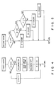
- the unit 30 reads blade counter data A, indicative of the frequency of operation of the blade 22, from the memory of the control device. If the data A is "10,” as shown in Fig. 5, the unit 30 reads the next blade counter data B. If the data A is not “10,” the unit 30 executes a subroutine "A-COUNT.” After the execution, the program returns to the main routine. If the counter data B is "8,” the unit 30 reads the next blade counter data C. If the data B is not “8,” the unit 30 executes a subroutine "B-COUNT.” After the execution, the program returns to the main routine. If the counter data C is "5,” the unit 30 executes a subroutine "D-COUNT,” whereupon the program returns to the main routine. If the counter data C is not “5,” a subroutine "C-COUNT” is executed, whereupon the program returns to the main routine.
- the control unit 30 first reads the counter data E, indicative of the number of prints, from the memory. If the data E is less than "600,” it is counted up by "+1,” whereupon the program returns to the main routine. If the data E is "600,” the unit 30 turns on the solenoid 25 to bring the blade 22 into contact with the surface of the drum 1. Thus, the drum is cleaned while it makes one revolution. Then, the unit 30 turns off the solenoid 25 to disengage the blade 22 from the drum 1. Thereafter, the unit 30 clears the counter data E, and counts up the counter data A by "+1,” whereupon the program returns to the main routine.
- the control unit 30 first reads the counter data E from the memory. If the data E is less than "600,” it is counted up by "+1,” whereupon the program returns to the main routine. If the data E is "600,” the unit 30 turns on the solenoid 25 to bring the blade 22 into contact with the surface of the drum 1. Thus, the drum is cleaned while it makes two revolutions. Then, the unit 30 turns off the solenoid 25 to disengage the blade 22 from the drum 1. Thereafter, the unit 30 clears the counter data E, and counts up the counter data B by "+1,” whereupon the program returns to the main routine.
- the control unit 30 first reads the counter data E from the memory. If the data E is less than "600,” it is counted up by "+1,” whereupon the program returns to the main routine. If the data E is "600,” the unit 30 turns on the solenoid 25 to bring the blade 22 into contact with the surface of the drum 1. Thus, the drum is cleaned while it makes three revolutions. Then, the unit 30 turns off the solenoid 25 to disengage the blade 22 from the drum 1. Thereafter, the unit 30 clears the counter data E, and counts up the counter data C by "+1,” whereupon the program returns to the main routine.
- the control unit 30 first reads the counter data E from the memory. If the data E is less than "600,” it is counted up by "+1,” whereupon the program returns to the main routine. If the data E is "600,” the unit 30 turns on the solenoid 25 to bring the blade 22 into contact with the surface of the drum 1. Thus, the drum is cleaned while it makes four revolutions. Then, the unit 30 turns off the solenoid 25 to disengage the blade 22 from the drum 1, and clears the counter data E, whereupon the program returns to the main routine.
- the unit 30 causes the drum 1 to make two revolutions while bringing the blade 22 into contact with the drum surface, thereby cleaning the drum, for each 600 prints.
- the unit 30 causes the drum 1 to make three revolutions while bringing the blade 22 into contact with the drum surface, thereby cleaning the drum, for each 600 prints.
- the unit 30 causes the drum 1 to make four revolutions while bringing the blade 22 into contact with the drum surface, thereby cleaning the drum, for each 600 prints.
- the residual toner adhering to the surface of the drum 1 can be securely removed.
- control unit 30 drives the mechanical cleaning system 20 for the regular operating times T0, T1, T2, T3, ..., equivalent to the period of time required for, e.g., one print, at gradually reducing rest-times t0, t1, t2, t3, ..., as shown in Fig. 3C.
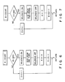
- the unit 30 reads the blade counter data A, indicative of the frequency of operation of the blade 22, from the memory of the control device. If the data A is "10,” as shown in Fig. 10, the unit 30 reads the next blade counter data B. If the data A is not “10,” the unit 30 executes the subroutine "A-COUNT.” After the execution, the program returns to the main routine. If the counter data B is "10,” the unit 30 reads the next blade counter data C. If the data B is not “10,” the unit 30 executes the subroutine "B-COUNT.” After the execution, the program returns to the main routine. If the counter data C is "10,” the unit 30 executes the subroutine "D-COUNT,” whereupon the program returns to the main routine. If the counter data C is not “10,” the subroutine "C-COUNT” is executed, whereupon the program returns to the main routine.
- the control unit 30 first reads the counter data E, indicative of the number of prints, from the memory. If the data E is less than "600,” it is counted up by "+1,” whereupon the program returns to the main routine. If the data E is "600,” the unit 30 turns on the solenoid 25 to bring the blade 22 into contact with the surface of the drum 1. Thus, the drum is cleaned while it makes one revolution. Then, the unit 30 turns off the solenoid 25 to disengage the blade 22 from the drum 1. Thereafter, the unit 30 clears the counter data E, and counts up the counter data A by "+1,” whereupon the program returns to the main routine.
- the control unit 30 first reads the counter data E from the memory. If the data E is less than "400,” it is counted up by "+1,” whereupon the program returns to the main routine. If the data E is "400,” the unit 30 turns on the solenoid 25 to bring the blade 22 into contact with the surface of the drum 1. Thus, the drum is cleaned while it makes one revolution. Then, the unit 30 turns off the solenoid 25 to disengage the blade 22 from the drum 1. Thereafter, the unit 30 clears the counter data E, and counts up the counter data B by "+1,” whereupon the program returns to the main routine.
- the control unit 30 first reads the counter data E from the memory. If the data E is less than "300,” it is counted up by "+1,” whereupon the program returns to the main routine. If the data E is "300,” the unit 30 turns on the solenoid 25 to bring the blade 22 into contact with the surface of the drum 1. Thus, the drum is cleaned while it makes one revolution. Then, the unit 30 turns off the solenoid 25 to disengage the blade 22 from the drum 1. Thereafter, the unit 30 clears the counter data E, and counts up the counter data C by "+1,” whereupon the program returns to the main routine.
- the control unit 30 first reads the counter data E from the memory. If the data E is less than "200,” it is counted up by "+1,” whereupon the program returns to the main routine. If the data E is "200,” the unit 30 turns on the solenoid 25 to bring the blade 22 into contact with the surface of the drum 1. Thus, the drum is cleaned while it makes one revolution. Then, the unit 30 turns off the solenoid 25 to disengage the blade 22 from the drum 1, and clears the counter data E, where upon the program returns to the main routine.
- the unit 30 causes the drum 1 to make one revolution while bringing the blade 22 into contact with the drum surface, thereby cleaning the drum, for each 400 prints.
- the unit 30 causes the drum 1 to make one revolution while bringing the blade 22 into contact with the drum surface, thereby cleaning the drum, for each 300 prints.
- the unit 30 causes the drum 1 to make one revolution while bringing the blade 22 into contact with the drum surface, thereby cleaning the drum, for each 200 prints.
- the result of printing may sometimes indicate unsatisfactory cleaning.
- a lot of defective prints will inevitably be produced until the control unit 30 causes, in each operating mode, the blade 22 to perform supplementary cleaning.
- an operator depresses the key 31 on the control panel of the automatic control device.
- an optional command signal is entered in the control unit 30, so that the unit 30 turns on the solenoid 25 to bring the blade 22 into contact with the drum surface, thereby effecting the supplementary cleaning, for the predetermined time Tr (equivalent to the period for one revolution of the drum), as shown in Fig. 15, even during a rest-time of the mechanical cleaning system 20.
- the operator can directly manually operate the blade 22 for the supplementary cleaning. More specifically, the operator can perform the supplementary cleaning by rotating the lever 24 in the direction of arrow A of Fig. 1 by means of the knob 24b, thereby bringing the blade 22 into contact with the surface of the drum 1.
- the cleaning capacity can be quickly increased as required to eliminate defective printing, without interrupting the operation of the apparatus.
- the magnetic cleaning system 14 integral with the developing device 4 is combined with the mechanical cleaning system 20 including the blade 22, and the control unit 30 is used to cause the blade 22 of the system 20 to touch and leave the surface of the photoreceptor drum 1.
- the drum 1, which are normally cleaned by means of the magnetic cleaning system 14 can enjoy automatic intermittent supplemental cleaning by means of the mechanical cleaning system 20, which supplements the cleaning capacity of the system 14.
- stable cleaning can be ensured for a long period of time, ano the print quality and printing efficiency can be prevented from lowering.
- the control unit 30 is designed so as to cause the blade 22 to repeat contact with and disengagement from the drum 1 at the predetermined time intervals. Accordingly, the blade 22 can be brought into contact with the drum 1 for supplementary cleaning at suitable time intervals. Thus, the cleaning capacity can be supplemented without damaging the surface of the drum 1.
- control unit 30 is designed so as to bring the blade 22 into contact with the drum 1 in response to an optional command signal even during a rest-time of the mechanical cleaning system 20. If defective printing is caused by unsatisfactory cleaning, therefore, the control unit 30 drives the mechanical cleaning system 20 to effect the supplementary cleaning in response to the optional comnand signal, thereby quickly compensating the deficiency in the cleaning effect. In consequence, the drum 1 can be stably cleaned for a longer period of time.
- the pressure of contact between the blade 22 and the drum 1 can be set higher than in the case of an apparatus in which a blade is always in contact with a drum. Accordingly, the residual toner, having failed to be removed by the magnetic cleaning system 14, can be easily scraped off by the blade 22. Also for this reason, prolonged stable cleaning can be ensured.
- the mechanical cleaning system 20 is constructed so that the blade 22 can be brought into contact with or disengaged from the drum 1 with suitable timing by manual operation from outside the apparatus. If unsatisfactory cleaning is revealed by the result of printing, therefore, the mechanical cleaning system 20 can be manually operated to supplement the cleaning capacity of the magnetic cleaning system 14.
- the cleaning capacity can be improved in accordance with the result of printing, without interrupting the operation of the apparatus. Consequently, the print quality and printing efficiency can be prevented from lowering for a long period of time.
- the mechanical cleaning system 20 is designed so that the blade 22 can be brought into contact with the drum 1 by manually rotating the lever 24. Accordingly, the pressure of contact between the blade 22 and the drum 1 can be suitably changed by adjusting the stroke of the blade 22. Thus, the cleaning capacity of the whole apparatus can be properly adjusted in accordance with the result of printing.
- the scale 8 for measuring the shift of the lever 24 is located in the vicinity of the opening 7a of the casing 7, so that the cleaning capacity can be easily adjusted by utilizing the scale 8.
- the waste toner receiving portion 23 of the mechanical cleaning system 20 need not be made large in size, thus constituting no hindrance to the reduction in size of the electrophotographic apparatus.
- the present invention is applicable also to an electrophotographic apparatus wherein development and magnetic cleaning are simultaneously performed by used of a developing device integral with a magnetic cleaning system.
- the lever 24 of the mechanical cleaning system 20 is designed so that its upper portion projects to the outside of the casing 7.
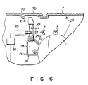
- the lever 24 may be arranged so that it cannot be carelessly operated to cause the blade 22 to damage the drum 1. More specifically, the whole lever 24 may be housed in the casing 7, as shown in Fig. 16, so that the lever 24 can be rotated manually to operate the blade 22 after lifting a cover 7b which is swingably attached to the opening 7a of the casing 7.
- the key 3 on the control panel is used as the means for entering the optional command signal in the control unit 30.
- a switch (not shown) for optional command signal output may be disposed at a position in the vicinity of the lever 24 or the like where the result of printing can be directly observed.
- the optional command signal is entered in the control unit 30 by means of the switch, which can be depressed while observing the printing result. If the printing result indicates unsatisfactory cleaning, the operator can immediately depress the switch to actuate the blade 22 for supplementary cleaning. Thus, defective printing can be more quickly eliminated.
- the output switch may be designed so that the optional command signal can be entered in the control unit 30 only while the switch is being manually depressed. Further, the switch may be arranged so as to be mechanically locked, thereby allowing the optional command signal to go on being inputted, when manually depressed.
Landscapes
- Physics & Mathematics (AREA)
- General Physics & Mathematics (AREA)
- Cleaning In Electrography (AREA)
- Control Or Security For Electrophotography (AREA)
Applications Claiming Priority (4)
| Application Number | Priority Date | Filing Date | Title |
|---|---|---|---|
| JP1117843A JP2530715B2 (ja) | 1989-05-11 | 1989-05-11 | 電子写真装置 |
| JP1117845A JPH02296276A (ja) | 1989-05-11 | 1989-05-11 | 電子写真装置 |
| JP117845/89 | 1989-05-11 | ||
| JP117843/89 | 1989-05-11 |
Publications (3)
| Publication Number | Publication Date |
|---|---|
| EP0397201A2 true EP0397201A2 (de) | 1990-11-14 |
| EP0397201A3 EP0397201A3 (de) | 1991-03-27 |
| EP0397201B1 EP0397201B1 (de) | 1994-08-10 |
Family
ID=26455888
Family Applications (1)
| Application Number | Title | Priority Date | Filing Date |
|---|---|---|---|
| EP90108931A Expired - Lifetime EP0397201B1 (de) | 1989-05-11 | 1990-05-11 | Elektrophotographisches Gerät |
Country Status (5)
| Country | Link |
|---|---|
| US (2) | US5073800A (de) |
| EP (1) | EP0397201B1 (de) |
| KR (1) | KR930008610B1 (de) |
| AU (1) | AU623251B2 (de) |
| DE (1) | DE69011394T2 (de) |
Families Citing this family (10)
| Publication number | Priority date | Publication date | Assignee | Title |
|---|---|---|---|---|
| JPH03208079A (ja) * | 1990-01-09 | 1991-09-11 | Sharp Corp | クリーニング装置 |
| US5258816A (en) * | 1990-01-26 | 1993-11-02 | Konica Corporation | Cleaning device for a color image forming apparatus |
| US5173735A (en) * | 1990-06-07 | 1992-12-22 | Minolta Camera Kabushiki Kaisha | Image forming apparatus with improved cleaning operation |
| JP2992421B2 (ja) * | 1992-12-22 | 1999-12-20 | 富士通株式会社 | 画像形成装置 |
| US5396320A (en) * | 1993-12-27 | 1995-03-07 | Xerox Corporation | Apparatus and method for cleaning a substrate in a printing apparatus |
| US5697017A (en) * | 1995-12-07 | 1997-12-09 | Lexmark International, Inc. | Image forming apparatus having process cartridge with shutter and cleaning member |
| US7650094B2 (en) * | 2004-11-12 | 2010-01-19 | Canon Kabushiki Kaisha | Image forming apparatus and controlling method |
| US7848680B2 (en) * | 2007-01-10 | 2010-12-07 | Kabushiki Kaisha Toshiba | Image forming apparatus and toner collection method |
| US8695503B2 (en) | 2011-08-31 | 2014-04-15 | Xerox Corporation | Apparatus and method for locking and actuating a stripper blade in a printer |
| US9400455B2 (en) * | 2013-03-15 | 2016-07-26 | Lexmark International, Inc. | Imaging device having an adaptable cleaning system |
Family Cites Families (17)
| Publication number | Priority date | Publication date | Assignee | Title |
|---|---|---|---|---|
| JPS5536153A (en) * | 1978-09-05 | 1980-03-13 | Yamaha Motor Co Ltd | Driving wheel shaft assembly of car |
| JPS56138773A (en) * | 1980-03-31 | 1981-10-29 | Mita Ind Co Ltd | Recovering method for developer |
| JPS5893085A (ja) * | 1981-11-27 | 1983-06-02 | Mita Ind Co Ltd | 静電式複写機のクリ−ニング装置 |
| JPS58149084A (ja) * | 1982-03-02 | 1983-09-05 | Ricoh Co Ltd | 複写機のクリ−ニング装置 |
| JPS58182674A (ja) * | 1982-04-20 | 1983-10-25 | Mita Ind Co Ltd | 静電複写機におけるクリ−ニング装置 |
| JPS59121370A (ja) * | 1982-12-28 | 1984-07-13 | Canon Inc | クリ−ニング方法 |
| US4664504A (en) * | 1983-01-20 | 1987-05-12 | Tokyo Shibaura Denki Kabushiki Kaisha | Image forming apparatus |
| JPS59198482A (ja) * | 1983-04-26 | 1984-11-10 | Konishiroku Photo Ind Co Ltd | クリ−ニング装置 |
| JPS6028684A (ja) * | 1983-07-27 | 1985-02-13 | Mita Ind Co Ltd | 電子写真法におけるトナ−クリ−ニング装置 |
| JPS60119589A (ja) * | 1983-12-02 | 1985-06-27 | Ricoh Co Ltd | 感光体のフイルミング除去装置 |
| FR2556757B1 (fr) * | 1983-12-14 | 1987-04-10 | Bouygues Sa | Treillis porteur tridimensionnel en beton et procede pour realiser ce treillis |
| JPS60153074A (ja) * | 1984-01-20 | 1985-08-12 | Fuji Xerox Co Ltd | 複写機用クリ−ニング機構の制御装置 |
| US4568174A (en) * | 1984-02-27 | 1986-02-04 | Xerox Corporation | Photoreceptor descumming device |
| JPS6292984A (ja) * | 1985-10-18 | 1987-04-28 | Konishiroku Photo Ind Co Ltd | クリ−ニング装置 |
| JPS62163081A (ja) * | 1986-01-13 | 1987-07-18 | Canon Inc | 画像形成装置 |
| JPS63250676A (ja) * | 1987-04-07 | 1988-10-18 | Konica Corp | クリ−ニング装置 |
| JP2741879B2 (ja) * | 1988-12-20 | 1998-04-22 | 株式会社リコー | 電子写真装置のクリーニング装置 |
-
1990
- 1990-05-03 US US07/518,653 patent/US5073800A/en not_active Ceased
- 1990-05-04 AU AU54674/90A patent/AU623251B2/en not_active Ceased
- 1990-05-09 KR KR1019900006568A patent/KR930008610B1/ko not_active Expired - Fee Related
- 1990-05-11 EP EP90108931A patent/EP0397201B1/de not_active Expired - Lifetime
- 1990-05-11 DE DE69011394T patent/DE69011394T2/de not_active Expired - Fee Related
-
1992
- 1992-11-25 US US07/981,260 patent/USRE34840E/en not_active Expired - Lifetime
Also Published As
| Publication number | Publication date |
|---|---|
| AU5467490A (en) | 1990-11-15 |
| USRE34840E (en) | 1995-01-31 |
| KR900018768A (ko) | 1990-12-22 |
| DE69011394D1 (de) | 1994-09-15 |
| DE69011394T2 (de) | 1995-03-30 |
| AU623251B2 (en) | 1992-05-07 |
| KR930008610B1 (ko) | 1993-09-10 |
| EP0397201A3 (de) | 1991-03-27 |
| EP0397201B1 (de) | 1994-08-10 |
| US5073800A (en) | 1991-12-17 |
Similar Documents
| Publication | Publication Date | Title |
|---|---|---|
| US4875063A (en) | Electrostatic recording apparatus | |
| US5038173A (en) | Replaceable unit determination mechanism | |
| EP0519526A2 (de) | Elektrofotografisches Farbgerät | |
| EP0397201A2 (de) | Elektrophotographisches Gerät | |
| JP2537559Y2 (ja) | 画像形成装置 | |
| GB2058400A (en) | Electrophotographic image forming apparatus | |
| US4806968A (en) | Drive unit for a copying machine | |
| JP3107391B2 (ja) | 画像形成装置 | |
| EP0203398B1 (de) | Bilderzeugungsgerät | |
| US4933720A (en) | Paper size selecting device in a recording apparatus | |
| JP2786657B2 (ja) | 画像形成装置 | |
| AU639854B2 (en) | Electrophotographic apparatus | |
| EP0247867A2 (de) | Reinigungsverfahren für den Fotoleiterträger eines Bilderzeugungsgerätes | |
| US5164781A (en) | Color image electrophotographic apparatus for printing long-size copy images | |
| EP0438160B1 (de) | Elektrofotografisches Gerät | |
| JP3059324B2 (ja) | 電子写真印刷装置 | |
| JP2530715B2 (ja) | 電子写真装置 | |
| JPH0527559A (ja) | 電子写真装置 | |
| JP2862805B2 (ja) | 画像印刷装置 | |
| JP3276140B2 (ja) | 画像形成装置およびその制御方法 | |
| JP3050933B2 (ja) | クリーナレス型画像形成装置 | |
| JPH07104642B2 (ja) | 電子写真装置 | |
| JPH0719110B2 (ja) | 編集機能付電子複写機 | |
| JPS61246782A (ja) | 複写装置 | |
| JPH02296276A (ja) | 電子写真装置 |
Legal Events
| Date | Code | Title | Description |
|---|---|---|---|
| PUAI | Public reference made under article 153(3) epc to a published international application that has entered the european phase |
Free format text: ORIGINAL CODE: 0009012 |
|
| 17P | Request for examination filed |
Effective date: 19900511 |
|
| AK | Designated contracting states |
Kind code of ref document: A2 Designated state(s): DE FR GB IT NL SE |
|
| PUAL | Search report despatched |
Free format text: ORIGINAL CODE: 0009013 |
|
| AK | Designated contracting states |
Kind code of ref document: A3 Designated state(s): DE FR GB IT NL SE |
|
| 17Q | First examination report despatched |
Effective date: 19921203 |
|
| GRAA | (expected) grant |
Free format text: ORIGINAL CODE: 0009210 |
|
| AK | Designated contracting states |
Kind code of ref document: B1 Designated state(s): DE FR GB IT NL SE |
|
| PG25 | Lapsed in a contracting state [announced via postgrant information from national office to epo] |
Ref country code: IT Free format text: LAPSE BECAUSE OF FAILURE TO SUBMIT A TRANSLATION OF THE DESCRIPTION OR TO PAY THE FEE WITHIN THE PRESCRIBED TIME-LIMIT;WARNING: LAPSES OF ITALIAN PATENTS WITH EFFECTIVE DATE BEFORE 2007 MAY HAVE OCCURRED AT ANY TIME BEFORE 2007. THE CORRECT EFFECTIVE DATE MAY BE DIFFERENT FROM THE ONE RECORDED. Effective date: 19940810 Ref country code: NL Effective date: 19940810 |
|
| REF | Corresponds to: |
Ref document number: 69011394 Country of ref document: DE Date of ref document: 19940915 |
|
| PG25 | Lapsed in a contracting state [announced via postgrant information from national office to epo] |
Ref country code: SE Effective date: 19941110 |
|
| ET | Fr: translation filed | ||
| NLV1 | Nl: lapsed or annulled due to failure to fulfill the requirements of art. 29p and 29m of the patents act | ||
| PLBE | No opposition filed within time limit |
Free format text: ORIGINAL CODE: 0009261 |
|
| STAA | Information on the status of an ep patent application or granted ep patent |
Free format text: STATUS: NO OPPOSITION FILED WITHIN TIME LIMIT |
|
| 26N | No opposition filed | ||
| PGFP | Annual fee paid to national office [announced via postgrant information from national office to epo] |
Ref country code: GB Payment date: 19960502 Year of fee payment: 7 |
|
| PGFP | Annual fee paid to national office [announced via postgrant information from national office to epo] |
Ref country code: FR Payment date: 19960510 Year of fee payment: 7 |
|
| PGFP | Annual fee paid to national office [announced via postgrant information from national office to epo] |
Ref country code: DE Payment date: 19960513 Year of fee payment: 7 |
|
| PG25 | Lapsed in a contracting state [announced via postgrant information from national office to epo] |
Ref country code: GB Effective date: 19970511 |
|
| GBPC | Gb: european patent ceased through non-payment of renewal fee |
Effective date: 19970511 |
|
| PG25 | Lapsed in a contracting state [announced via postgrant information from national office to epo] |
Ref country code: FR Free format text: LAPSE BECAUSE OF NON-PAYMENT OF DUE FEES Effective date: 19980130 |
|
| PG25 | Lapsed in a contracting state [announced via postgrant information from national office to epo] |
Ref country code: DE Free format text: LAPSE BECAUSE OF NON-PAYMENT OF DUE FEES Effective date: 19980203 |
|
| REG | Reference to a national code |
Ref country code: FR Ref legal event code: ST |