EP0395404A2 - Bildverarbeitungsvorrichtung - Google Patents
Bildverarbeitungsvorrichtung Download PDFInfo
- Publication number
- EP0395404A2 EP0395404A2 EP90304516A EP90304516A EP0395404A2 EP 0395404 A2 EP0395404 A2 EP 0395404A2 EP 90304516 A EP90304516 A EP 90304516A EP 90304516 A EP90304516 A EP 90304516A EP 0395404 A2 EP0395404 A2 EP 0395404A2
- Authority
- EP
- European Patent Office
- Prior art keywords
- data
- pixel
- region
- binarization
- error
- Prior art date
- Legal status (The legal status is an assumption and is not a legal conclusion. Google has not performed a legal analysis and makes no representation as to the accuracy of the status listed.)
- Granted
Links
Images


Classifications
-
- H—ELECTRICITY
- H04—ELECTRIC COMMUNICATION TECHNIQUE
- H04N—PICTORIAL COMMUNICATION, e.g. TELEVISION
- H04N1/00—Scanning, transmission or reproduction of documents or the like, e.g. facsimile transmission; Details thereof
- H04N1/40—Picture signal circuits
- H04N1/405—Halftoning, i.e. converting the picture signal of a continuous-tone original into a corresponding signal showing only two levels
- H04N1/4051—Halftoning, i.e. converting the picture signal of a continuous-tone original into a corresponding signal showing only two levels producing a dispersed dots halftone pattern, the dots having substantially the same size
- H04N1/4052—Halftoning, i.e. converting the picture signal of a continuous-tone original into a corresponding signal showing only two levels producing a dispersed dots halftone pattern, the dots having substantially the same size by error diffusion, i.e. transferring the binarising error to neighbouring dot decisions
Definitions
- the present invention relates to an image processing apparatus which executes quantization of image data into binary data or multi-level data, particularly the image processing apparatus which executes intermediate shade (or gradation) processing of input image data.
- the error diffusion method is the method to binarize the multi-level image data of objective pixel (to convert into darkest level or shortest level), give specific weight to the difference between the binarized level and multi-level image data prior to binarization and add it on the data of pixel near the objective pixel as disclosed in the literature of R. Floyd & L. Steinberg entitled "An adaptive algorithm for spatial gray scale", SUD 75 DIGEST, PP. 36 - 37.
- the average density, approximation method is the method, as described in Japanese Unexamined Patent Publication (Kokai) No. 57-104396, wherein the weighted means value of the respective weights of the objective pixel binarized into black and white and that of the neighbouring pixel are obtained using the already binarized binary data of the pixel near the objective pixel and thereby the image data of the objective pixel are binarized using the average of the two mean values as the threshold.
- the aforesaid error diffusion method is the method to correct the error between the input image data and the output image data, it is possible to maintain the input image and the density of the output image processing unit and produce the image with excellent resolution and shade characteristics.
- the error diffusion method has such drawback that at the point near the starting point of binarization of divided image, the error for correction is not transmitted and it tends to become the so-called binarization processing by fixed threshold.
- the average density approximation method has such drawback that at the calculation of average density, the already binarized data are not repeated and consequently the expression of intermediate shade becomes discontinuous at the connecting part between the divided images after binarization processing and thus picture quality deteriorates.
- the present invention has been made with the objective to solve the aforesaid problems and it provides an image processing apparatus which can substantially reduce the processing volume for quantization and at the same time reproduce an image with excellent intermediate shade (or an excellent halftone image).
- Another objective of the present invention is to provide an image processing apparatus which gives an accurate semi-intermediate shade to the terminal part of the binarized image in the serial scanning which has been the problem of the conventional method.
- Still another object of the present invention is to provide an image processing apparatus wherein the binary data at the terminal of each scanning are maintained until the execution of the succeeding scan in the serial scanning so that in the succeeding scan an average weighted density in reference to such binary data is obtained and thereby the continuity of the data at the connection between scans is established and an image with excellent shade characteristic (or gradation) and resolution is obtained.
- Still another objective of the present invention is to provide an image processing apparatus which binarizes the multiple-level image data by the average value based on the binarized data within the specific range and which is equipped with the discriminating means to tell that no binary data exist at least at a part of the said specified range and a multiple-level data conversion means which converts the pixel having no binary data discriminated by the said discriminating means into the normalized multiple-level data.
- a weighted average density based on the binary data can be obtained equivalently using the multiple-level data at such position and an effective binarization can be made even at the terminal part of the image.
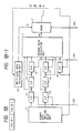
- Fig. 1A is the block diagram of the image processing apparatus of the present embodiment.
- Fig. 1A 100 is the image read unit to read the image of the manuscript (or original) wherein the read analogue image signal is input into quantization unit 101, converted into digital signal, given publicly known correction processing such as logarithmic conversion, shading correction, etc. and the data 200 used for recording is obtained.
- the said data 200 is input into the binarization processing unit 102 where the present system is executed, binarized and output as the binarized signal 201 and binary image is produced as the semi-intermediate shade at image output unit 103.
- the binarization processing unit 102 is composed of the data switch unit 102b which switches binary data 201 and multiple-level data 200 in the calculation of average density, average density maintenance unit 102a comprising the average density calculation processing unit and error diffusion processing unit and switch control unit 102c which controls switching at the data switch unit 102b.
- the image processing equipment of this embodiment is the so-called serial scanning unit which reads the manuscript in bands with width of l and length of m and reproduce it as binary data.
- f (i, j) indicates the multiple density data of input image at the objective pixel to be binarized and the values are the normalized 0 - 1 value.
- the pixel position above the dotted line is already binarized and after binarization of objective pixel, the similar processing is executed one after another in the order of f (i, j+1), f (i, j+2), ...
- Fig. 2B is the diagram to show the binarized image data and B (i, j) shows the density of objective pixel after binarization (the values of 0 or 1).
- the part surrounded by dotted lines is the pixel data which are already binarized at the time of processing of objective pixel and they are used at the binarization processing of objective pixel.
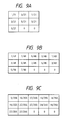
- Fig. 2C is the drawing to show the weight-giving mask
- Fig. 2D is the drawing to show the example of actual figures of weight-giving mask.
- the multiple-level density f (i, j) of the objective pixel is binarized by the following formula.
- E (i, j) is the error which is produced when the multiple-level density (i, j-1) of the pixel (i, j-1) one position prior to the objective pixel (i, j) is binarized into binary density B (i, j-1).
- Binarization of input pixel density of (i, j-1) into 1 or 0 means that the pixel (i, j-1) has been approximated into either ml (i, j-1) or m0 (i, j-1) which represent the average density in its neighbourhood and in each case, an error of f (i, j-1) - ml or f (i, j-1) - m0 is generated between such density and the multiple-level density f (i, j-1) of input pixel. Therefore, by binarizing the value corrected by adding such binarized error E (i, j) to the objective pixel of (i, j), it is possible to completely maintain the density of the binarized image for the entire range of input image.
- the most important characteristic of this system is in such processing method that takes into account the error of binarization thus providing by far better intermediate shade reproducing potency when compared to the aforesaid average density approximation method.
- E (i, j+1) is the balance given by subtracting m1 from f (i, j) + E (i, j) when f (i, j) + E (i, j) > (m1 + m0)/2 and the balance given by subtracting m0 from f (i, j) + E (i, j) when f (i, j) + E (i, j) ⁇ (m1 + m0)/2.
- the aforesaid average density approximation method does not consider the error as taken into account by this method and it is evident that the image reproducing potency of this method is better than that of the average density approximation method.
- the width of the image input at image reading unit 100 should be l + 2 pixel by adding one pixel at both sides and the length should be m + 2 pixels by adding 2 pixels on top, while the multi-level data of 3 pixels at the left end in j direction immediately preceding thereto and two pixels at the right end in j direction or 2 pixels at the upper end in i direction are maintained.
- the upper end part in i direction and left end part of scan (I) require the similar processing as aforesaid but in this embodiment, binarized data of several lines at the upper end and the left end are neglected by regarding the data below several lines at the end part as effective image region.
- the objective pixel f (i, j) indicated in Fig. 2A is the starting point of binarization of the image
- 7 pixels in the binarized image surrounded by the dotted lines are not binarized and the objective pixel f (i, j) can not be binarized according to the aforesaid algorithm. Therefore, in this embodiment the weighted average values m1 and m0 of the said point are calculated by using multi-level data.
- B (i-2, j-1) is substituted by f (i-2, j-1)
- B (i-2, j) is substituted by f (i-2, j)
- B (i-2, j+1) is substituted by f (i-2, j+1)
- B (i-1, j-1) by f (i-1, j-1)
- B (i-2, j) by f (i-1, j+1)
- B (i, j-1) by f (i, j-1) and in this way average values in and m0 are calculated to obtain B (i, j).
- each pixel is binarized one after another by calculating m1 and m0 using the binarized data and multiple-level data in the same way as above.
- the detailed circuit block shown in Fig. 1B illustrates the block of the binarized processing which is even free from the discontinuity inherent to the error diffusion having been added by this system.
- the binary data of D flipflop (hereinafter called D ⁇ F/F) 12, 13, 14, 15, 16, 17 and 18 and those of FIFO 11 which delays the binary data by 2 lines are simultaneously entered while maintaining the relative position of 7 pixels surrounded by the dotted line in Fig. 2A and the aforesaid average density m0 is output.
- data conversion is executed based on the binary data of 7 pixels and the preset standardized weight R (x, y) as shown in Figs. 2C and 2D.
- Average calculation unit 1 is composed of ROM.
- Adder 2 function only at the starting point and end point of binarization and the weighted average value (added value) for 3 or 2 pixels based on the multiple-level data calculated at multiple-level data calculation unit 10 is added to the aforesaid ROM output i.e., the weighted average value m0 based on other binary data.
- the binary data corresponding to the output of the said multiple-level data calculating part 10 i.e., the output of D ⁇ F/F 14, 17 and 18 or D ⁇ F/F 12 and 15 are primarily reset to "0" by the timing generation circuit output not shown in the drawing.
- the operating signal of the aforesaid adder 2 and reset signal D ⁇ F/F are the switch signal 203 shown in Fig. 1A.
- the binarization and error calculation section 3 to be composed of comparator 3a and subtracter 3b outputs the binarized results of the image from the multiple-level data (f + E) corrected and standardized by the error to be started later and the weighted average value (m0 + f0) and the already known weight R (0, 0), according to the formula 3. Simultaneously, binarized results are input into the binary data two line delay unit 11.
- the output of the said adder 9 is input into the E2 line memory 7 and delayed by one line.
- 5 is the adder which corrects the data corrected only for the output of the said E2 line memory 7 i.e., the objective ith line E2, by adding the error E1 wherein error E1 is usually selected as it is by multiplexer 6 and input into the said adder 5.
- E1 error connection memory 8 is the memory which stores the E1 error to be carried over the added to the leading pixel of the scan (II) until the execution of the succeeding scan (II), the said addition being done when the final pixel of each ith line is binarized and binarization is executed in j direction for each line at the execution of the next scan i.e., the scan (I) in Fig. 3 and the pixel at the boundary to the scan (II) is binarized.
- the memorized E1 data is read at the time of execution of scan (II) and only when the leading pixel is binarized, it is selected by multi-multiplexer 6 and added to the aforesaid adder 5.
- the error may be transmitted to the binarization processing of the leading pixel by the E1 error connection memory 8.
- the data corrected by error E1 and E2 are delayed by D ⁇ F/F 4 by one pixel and input into the said binarization and error calculating unit 3 and the same action is repeated pixel by pixel.
- Multiple-level data calculating unit 10 is composed of 5 D ⁇ F/Fs and an adder and it can execute the said performance easily when it is so arranged that it maintains by latch the leading multiple-level data and terminal multiple-level data line by line and maintains it by shifting the internal D ⁇ F/F according to the 1 line synchro-signal.
- the calculating volume of multiple-level calculating unit becomes large, but sufficient effect is obtained if, for example, f (i, j) is 8 bit data length, calculation is done by using the upper 2 or 3 bits.
- the average calculation unit executes multiplication and addition calculation of 1 bit data and fixed value, it is possible to execute calculation by making it a several hundred gate integrated circuit using gate array etc. even without using ROM and in Fig. 1B, it can be executed by the gate array of 2 - 3000 gates except for memory.
- the distribution of error is not limited to 2 pixels and the region of average value calculation mask and its weight are not limited to this embodiment.
- image processing equipment is provided wherein the binarized image terminal can be accurately processed for semi - intermediate shade in the serial scanning.
- Fig. 2A is the drawing to indicate the multiple-level density of each pixel of the input image.
- f (i, j) indicates the multiple density data of input image at the objective pixel position to be binarized and they shall be expressed in the normalized 0-1 value.
- the pixel position above the dotted line is already binarized and after binarization of objective pixel the similar binarization is conducted for f (i, j+1), f (i, j+2), ... one after another.
- Fig. 1B is the drawing to show the binarized image data and B (i, j) indicates the density after binarization of objective pixel (expressed by "0" or "1").
- the part surrounded by dotted line is the pixel data which has already been binarized at the time of processing of objective pixel and they are used at the binarization of the objective pixel.
- Fig. 1C is the drawing to show the weighted mask.
- R is an example of weighted mask to obtain the average density and it is expressed by the matrix of 3 x 3 size.
- the weighted average density of binary image in the neighbourhood of the objective pixel is named m (i, j) and it is calculated by the following formula;
- Objective pixel f (i, j) is binarized by the following formulae 5 using the said average density m (i, j) and already allotted binarized correction value E (i, j).
- Figs. 5A and 5B indicate the aforesaid formulae 5 in diagram.
- E (i, j) is the sum of the error produced when multiple-level density f (i, j-1) of the pixel one step prior to the objective pixel (i, j) or pixel (i, j-1) is binarized into binarized density B (i, j-1), i.e., 1/2 of the difference between the multiple denisty f (i, j-1) and the average density m (i, j-1) in the neighbourhood and the error produced when the multiple-level density f (i-1, j) of the pixel one line prior to the objective pixel (i, j), i.e., 1/2 of the difference between multiple-level density f (i-1, j) and the average density in the neighbourhood m (i-1, j).
- intermeidate shade reproducing potency greatly improves when compared to the aforesaid average density approximation method.
- E1 (i, j+1) is the error alotted to the pixel (i, j+1), which is one pixel after the objective pixel (i, j) while E2 (i-1, j) is the error allotted to the pixel (i+1, j) one line after the objective pixel (i, j).
- the binarization system in this embodiment provides the image reproducing potency equal or better than the binarization by the conventional error diffusion process in spite that the processing volume is extremely small. It is because in spite that the said error is corrected only by the two adjacent pixels, by obtaining the average density from the binarized plural number of data, the same effect is obtained to the case of correction made by distribution of the error equivalently to plural number of pixels.
- Fig. 6 is the block diagram of the image processing equipment of the present embodiment.
- input sensor unit A is composed of photoelectric conversion device such as CCD and the driving equipment for scanning and it scans and reads the manuscript and the image data of the manuscript read by input sensor A are delivered to the A/D converter B one after another.
- A/D converter B converts the data of each pixel into 8 bit digital data and quantizes it into the data with 256 levels of shades (gradation).
- shading correction is effected by digital calculation for correction of irregularity of the sensitivity of CCD sensor at input sensor unit A and irregularity of illuminance caused by illumination source.
- the data already corrected by correction circuit C is delivered to the binarization circuit D.
- the 8 bit multiple-level image data input by the correction circuit C is quantized into 1 bit binary data by the aforesaid system of the present embodiment.
- Printer E is the printer which is composed of laser beam or ink jet system and reproduces the read image on the recording sheet by on/off control of printed dots based on the binary data delivered from binarized circuit D.
- the multiple-level data of the said two pixels to be processed in the succeeding scan (II) are overlappingly read and they are applied by substituting the binary data.
- the binary data of the said 3 pixels are memorized by the data maintenance means of the present embodiment at the time when they are binarized in the preceding scan (I) and they are applied by substituting the present data.
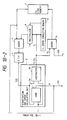
- Fig. 7 illustrates the detailed block composition of the binarized section based on the aforesaid algorithm in binarized circuit D of the present embodiment.
- 701 is the average value calculating unit wherein by the delay unit 711 comprising the FIFO buffer which delays the flip-flop (F/F) 712 - 718 and binarized data by 2 lines, the mutual binarized data are simultaneously input while maintaining the relative positions of 7 pixels surrounded by dotted line in Fig. 2A and thus the aforesaid average density m is output, and 701 is composed of ROM which executes data conversion based on the preset weight R.
- the adder 702 is the adder which functions only at the end point of binarization but it adds the weighted average density (added value) of 2 pixels based on the multiple-level data calculated by the multiple-level data calculating unit 710 on to a part of the weighted average density m based on other binarized data output from the ROM of the average operating unit 701.
- the binary data corresponding to the output from the multiple-level data calculating unit 710 i.e., F/F12 and 15 output are primarily reset at "0" by the timing generation circuit output not shown in the drawing.
- the binarization and error calculation unit 703 is the binarization and error calculation unit which is composed of comparator and deductor and it outputs the multiple-level data (f + E) corrected by the specified error to be stated later and the binarized data of the image based on the weighted average density m.
- This binarized data output can also be output at the delay unit 711.
- E2 multiple-level data of input from one side are first corrected by error E2.
- the correction output from adder 709 is input into E2 line.
- adder 705 At one side of adder 705 is input the delay output from E2 line memory 707 which is the correction output coming from adder 709, i.e., the data corrected only by E2 at the objective ith line and further correction is conducted by adding error E1 to the aforesaid correction data at the said adder 705.
- the output data from the adder 705 which has been corrected by E1 and E2 are delayed by one pixel by D type F/F 704 and input into binarization and error calculation unit 703 and the aforesaid actions are repeated for each pixel.
- the multiple-level data calculating section 701 may be composed of two D type F/F and an adder. Its function can be easily executed when it takes such construction that it latches and maintains line by line the multiple-level data for one pixel which belongs to the succeeding scanning region and shifts and maintains the internal F/F according to one line synchro-signal.
- binarized data given out by the binarization and error calculation unit 703 are also output at binary connection memory 719.
- Binary connection memory 719 stores only the binarized data at the terminal section of each line synchronizing with one line synchro signal, out of all the binarized output of binarization and error calculation unit 703 and after delaying it by one scanning period, outputs it at multiplexer 730. When multiplexer 730 is selected, the data are input in F/F 718 and delay section 711.
- the said processing takes place only at the starting end of the line at each scanning time after scanning (II) and average value calculation unit 701 handles the said data as the binary data of the pixel at the place T pixels prior to the starting point of line binarization.
- more accurate binarization may be conducted by constructing the binarization circuit D in such way that the error E1 having generated at the binarization of the terminal pixel of each line in the preceding scan (the error to be used for correction of leading pixel of each line in the succeeding scanning region) is carried over for correction.
- the error connection memory 720 is the memory which, at the time of binarization of the terminal pixel of each line in j direction at the execution of scan (I), stores the error E1 to be carried over and added to the leading pixel of the succeeding scan until the succeeding scan i.e., scan (II) is executed and the E1 data memorized by the error connection memory 720 is read at the execution of scan (II) and only at the time of binarization of the leading pixel, it is selected by the multiplexer 721 and input into the aforesaid adder 5 and corrects only the said leading pixel.
- the binary data of the terminal part of each scan is preserved until the succeeding scan is executed and at the execution of the succeeding scan, the data are referred to and by obtaining the weighted average density based on the binary data the leading pixel of each scan is also corrected, thus the data not becoming discontinuous at the connection of scans and the image with excellent gradation and resolution being obtained.
- the binary connection memory 719 which delays and holds the binary data during one scan so that they are used for the calculation of the average value m at the time of binarization of the leading pixel at each line of the succeeding scan as explained in the 2nd embodiment and the error connection memory 720 which delays and holds the E1 error data to be used for correction of the said pixel at the binarization of the said pixel as explained in the 3rd embodiment are so controlled that their writing and reading are executed by the same timing and the data of the two combined are less than 8 bit.
- composition can all be constructed on one chip.
- the weight mask of 3 x 3 matrix as shown in Fig. 9A is used but to smoothly binarize the intermediate section, it is generally desirable to set the weight of the pixel adjacent to the objective pixel smaller.
- Multiple-level data calculation unit 710 bears a large calculation load when weighted mask becomes over 3 x 3 but if for example f is 8 bit data length, the calculation may be done using about 2 - 3 bits of the superior position and yet satisfactory effect is obtained.
- the processing speed may be further increased. It goes without saying that by bulding it into the gate array etc., the scale of hardware can be substantially reduced.
- the error is equally distributed over 2 pixels but distribution of such error is not limited to two pixels neither the ratio of distribution is not limited to equal ratio but may be distributed to an arbitrarily selected pixel.
- the distribution of error is neither restricted by the average value calculation mask region or its weight.
- the kind of input data is one (one color) but the input data of the present invention are not limited to one color but the data input may be made in 3 colors, red (R), green (G) and blue (B) and it may be applied to the color image processing equipment.
Landscapes
- Engineering & Computer Science (AREA)
- Multimedia (AREA)
- Signal Processing (AREA)
- Facsimile Image Signal Circuits (AREA)
- Image Processing (AREA)
Applications Claiming Priority (6)
| Application Number | Priority Date | Filing Date | Title |
|---|---|---|---|
| JP1105877A JP2755309B2 (ja) | 1989-04-27 | 1989-04-27 | 画像処理装置 |
| JP105877/89 | 1989-04-27 | ||
| JP10587789 | 1989-04-27 | ||
| JP1246526A JP2848566B2 (ja) | 1989-09-25 | 1989-09-25 | 画像処理装置 |
| JP246526/89 | 1989-09-25 | ||
| JP24652689 | 1989-09-25 |
Publications (3)
| Publication Number | Publication Date |
|---|---|
| EP0395404A2 true EP0395404A2 (de) | 1990-10-31 |
| EP0395404A3 EP0395404A3 (de) | 1992-06-03 |
| EP0395404B1 EP0395404B1 (de) | 1999-12-01 |
Family
ID=26446094
Family Applications (1)
| Application Number | Title | Priority Date | Filing Date |
|---|---|---|---|
| EP90304516A Expired - Lifetime EP0395404B1 (de) | 1989-04-27 | 1990-04-26 | Bildverarbeitungsvorrichtung |
Country Status (3)
| Country | Link |
|---|---|
| US (1) | US5121447A (de) |
| EP (1) | EP0395404B1 (de) |
| DE (1) | DE69033372T2 (de) |
Cited By (7)
| Publication number | Priority date | Publication date | Assignee | Title |
|---|---|---|---|---|
| EP0576786A2 (de) * | 1992-07-01 | 1994-01-05 | Hewlett-Packard Company | Fehlerdiffusionsprozessor und Verfahren zur Umwandlung eines Bildes mit Grauskalaelementen in ein Bild mit Binärwertelementen |
| EP0606987A2 (de) * | 1993-01-11 | 1994-07-20 | Canon Kabushiki Kaisha | Paralleles Fehlerdiffusionsverfahren und -gerät |
| EP0626672A2 (de) * | 1993-05-25 | 1994-11-30 | Canon Kabushiki Kaisha | Verfahren und Einrichtung zum Anzeigen von Halbtönen in einer ferroelektrischen Flüssigkristallanzeige mit Abtastung in Streifeneinheiten |
| AU674551B2 (en) * | 1993-01-11 | 1997-01-02 | Canon Kabushiki Kaisha | Block parallel error diffusion method and apparatus |
| EP0855831A2 (de) * | 1997-01-28 | 1998-07-29 | Hewlett-Packard Company | Bildwiedergabe mittels mehrzeiliger Fehlerdiffusion für schnellere Wirkung und kleinere integrierte Schaltungen |
| EP0889642A2 (de) * | 1997-07-04 | 1999-01-07 | SAMSUNG ELECTRONICS Co. Ltd. | Bildverarbeitungsvorrichtung und verfahren |
| EP0954164A3 (de) * | 1998-04-30 | 2003-12-17 | Hewlett-Packard Company, A Delaware Corporation | Drucker mit Progressivspalten- und Fehlerdiffusionsystem und Verfahren zu dessen Verwendung zur Verbesserung des Durchsatzes des Druckers |
Families Citing this family (36)
| Publication number | Priority date | Publication date | Assignee | Title |
|---|---|---|---|---|
| US5760918A (en) * | 1989-09-27 | 1998-06-02 | Canon Kabushiki Kaisha | Image processing apparatus with conversion and reconversion of the number of bits per pixel |
| JP3038816B2 (ja) * | 1990-06-27 | 2000-05-08 | 株式会社リコー | 画像処理装置 |
| DE69126250T2 (de) * | 1990-07-20 | 1997-10-09 | Canon Kk | Vorrichtung zur Bildverarbeitung |
| JPH04175065A (ja) * | 1990-11-08 | 1992-06-23 | Canon Inc | 画像処理装置 |
| US5394250A (en) * | 1991-03-10 | 1995-02-28 | Canon Kabushiki Kaisha | Image processing capable of handling multi-level image data without deterioration of image quality in highlight areas |
| US5388167A (en) * | 1991-03-12 | 1995-02-07 | Hitachi, Ltd. | Document image processing system and document image processing method |
| JP3087767B2 (ja) * | 1991-03-15 | 2000-09-11 | キヤノン株式会社 | 画像処理装置 |
| JPH0591328A (ja) * | 1991-09-30 | 1993-04-09 | Ricoh Co Ltd | 画像処理装置 |
| US5271070A (en) * | 1992-11-06 | 1993-12-14 | Xerox Corporation | Multi-dimensional error diffusion technique |
| US5825919A (en) * | 1992-12-17 | 1998-10-20 | Xerox Corporation | Technique for generating bounding boxes for word spotting in bitmap images |
| DE69329449T2 (de) | 1993-01-01 | 2001-03-08 | Canon Kk | Bildverarbeitungsvorrichtung und -verfahren |
| WO1994017491A1 (en) * | 1993-01-27 | 1994-08-04 | United Parcel Service Of America, Inc. | Method and apparatus for thresholding images |
| JP3437226B2 (ja) * | 1993-10-20 | 2003-08-18 | キヤノン株式会社 | 画像処理方法及び装置 |
| JP3305495B2 (ja) * | 1994-04-28 | 2002-07-22 | キヤノン株式会社 | 画像処理装置および画像処理方法 |
| JPH07307866A (ja) * | 1994-05-10 | 1995-11-21 | Fuji Photo Film Co Ltd | 画像信号2値化処理装置および方法 |
| US5528384A (en) * | 1994-08-03 | 1996-06-18 | Xerox Corporation | System and method for implementing fast high addressability error diffusion process |
| JPH08111777A (ja) * | 1994-10-07 | 1996-04-30 | Brother Ind Ltd | 画像処理装置 |
| US5825940A (en) * | 1995-01-23 | 1998-10-20 | Canon Kabushiki Kaisha | Image processing method and apparatus for binary-coding multivalue image data |
| US6067088A (en) * | 1995-05-18 | 2000-05-23 | Canon Kabushiki Kaisha | Image processing method and apparatus thereof |
| JPH0983792A (ja) * | 1995-09-20 | 1997-03-28 | Canon Inc | 画像処理装置及びその方法 |
| US5933539A (en) * | 1996-05-30 | 1999-08-03 | Xerox Corporation | Method and system for hybrid error diffusion processing of image information using programmable screen modulation |
| US6249357B1 (en) | 1996-05-30 | 2001-06-19 | Xerox Corporation | System and apparatus for tonal reproduction curve adjustment in a hybrid error diffusion process |
| JPH1093820A (ja) * | 1996-05-30 | 1998-04-10 | Xerox Corp | 誤差拡散方法及び誤差拡散システム |
| US5787206A (en) * | 1996-05-30 | 1998-07-28 | Xerox Corporation | Method and system for processing image information using expanded dynamic screening and error diffusion |
| US5822464A (en) * | 1996-05-30 | 1998-10-13 | Xerox Corporation | Method and system for processing image information using video dependent dampened screening and error diffusion |
| US5809177A (en) * | 1996-06-06 | 1998-09-15 | Xerox Corporation | Hybrid error diffusion pattern shifting reduction using programmable threshold perturbation |
| US5903361A (en) * | 1996-06-06 | 1999-05-11 | Xerox Corporation | Method and system for processing image information using background error diffusion |
| US5754706A (en) * | 1996-06-19 | 1998-05-19 | Xerox Corporation | System and apparatus for single subpixel elimination in an high addressable error diffusion process |
| JP3095140B2 (ja) * | 1997-03-10 | 2000-10-03 | 三星電子株式会社 | ブロック化効果の低減のための一次元信号適応フィルター及びフィルタリング方法 |
| USRE37755E1 (en) * | 1997-05-29 | 2002-06-18 | Samsung Electronics Co., Ltd. | Interpolation method for binary image |
| KR100314098B1 (ko) * | 1997-05-29 | 2001-12-12 | 윤종용 | 주위화소값의적응임계치를이용한이진영상보간방법 |
| US6449061B2 (en) * | 1997-09-23 | 2002-09-10 | Xerox Corporation | System and method for providing dynamic noise profile selection for hybrid and error diffusion image processing |
| JP3717725B2 (ja) * | 1999-10-07 | 2005-11-16 | 三洋電機株式会社 | 画素欠陥検出方法及び画像処理装置 |
| KR100791389B1 (ko) * | 2006-12-26 | 2008-01-07 | 삼성전자주식회사 | 스트럭쳐드 라이트를 이용한 거리 측정 장치 및 방법 |
| JP5971068B2 (ja) * | 2012-10-02 | 2016-08-17 | 富士ゼロックス株式会社 | 画像処理装置、画像形成システム、及び画像処理プログラム |
| WO2023076969A1 (en) * | 2021-10-27 | 2023-05-04 | Maxlinear, Inc. | Current information sharing of constant-on-time point-of-load converters |
Citations (8)
| Publication number | Priority date | Publication date | Assignee | Title |
|---|---|---|---|---|
| US4196452A (en) | 1978-12-01 | 1980-04-01 | Xerox Corporation | Tone error control for image contour removal |
| JPS6431408A (en) | 1987-07-28 | 1989-02-01 | Elna Co Ltd | Electrolyte for driving electrolytic capacitor |
| JPS6431404A (en) | 1987-07-28 | 1989-02-01 | Matsushita Electric Ind Co Ltd | Rotary transformer and manufacture thereof |
| JPS6431411A (en) | 1987-07-28 | 1989-02-01 | Toshiba Corp | Device for closing tube opening of heat treatment furnace |
| JPS6431405A (en) | 1987-07-27 | 1989-02-01 | Matsushita Electric Works Ltd | Ballast mounting structure for discharge lamp apparatus |
| JPS6431409A (en) | 1987-07-28 | 1989-02-01 | Toshiba Corp | Capacitor |
| JPH01284879A (ja) | 1988-05-12 | 1989-11-16 | Canon Inc | 電子写真法 |
| US4958236A (en) | 1987-06-11 | 1990-09-18 | Canon Kabushiki Kaisha | Image processing method and apparatus therefor |
Family Cites Families (10)
| Publication number | Priority date | Publication date | Assignee | Title |
|---|---|---|---|---|
| JPS57104369A (en) * | 1980-12-22 | 1982-06-29 | Toshiba Corp | Binary device for picture with contrast |
| US4554593A (en) * | 1981-01-02 | 1985-11-19 | International Business Machines Corporation | Universal thresholder/discriminator |
| US4709274A (en) * | 1983-08-29 | 1987-11-24 | Canon Kabushiki Kaisha | Image processing apparatus |
| US4692811A (en) * | 1984-07-25 | 1987-09-08 | Matsushita Electric Industrial Co., Ltd. | Apparatus for processing image signal |
| US4577235A (en) * | 1984-08-20 | 1986-03-18 | The Mead Corporation | Text/continuous tone image decision processor |
| US4821334A (en) * | 1984-12-28 | 1989-04-11 | Canon Kabushiki Kaisha | Image processing apparatus |
| JP2702928B2 (ja) * | 1987-06-19 | 1998-01-26 | 株式会社日立製作所 | 画像入力装置 |
| US4975786A (en) * | 1987-12-28 | 1990-12-04 | Canon Kabushiki Kaisha | Image processing method and apparatus with error diffusion capability |
| US4969052A (en) * | 1988-05-11 | 1990-11-06 | Canon Kabushiki Kaisha | Image processing method and apparatus |
| EP0382581B1 (de) * | 1989-02-10 | 1996-05-08 | Canon Kabushiki Kaisha | Bildverarbeitungsvorrichtung |
-
1990
- 1990-04-26 US US07/514,616 patent/US5121447A/en not_active Expired - Lifetime
- 1990-04-26 EP EP90304516A patent/EP0395404B1/de not_active Expired - Lifetime
- 1990-04-26 DE DE69033372T patent/DE69033372T2/de not_active Expired - Fee Related
Patent Citations (8)
| Publication number | Priority date | Publication date | Assignee | Title |
|---|---|---|---|---|
| US4196452A (en) | 1978-12-01 | 1980-04-01 | Xerox Corporation | Tone error control for image contour removal |
| US4958236A (en) | 1987-06-11 | 1990-09-18 | Canon Kabushiki Kaisha | Image processing method and apparatus therefor |
| JPS6431405A (en) | 1987-07-27 | 1989-02-01 | Matsushita Electric Works Ltd | Ballast mounting structure for discharge lamp apparatus |
| JPS6431408A (en) | 1987-07-28 | 1989-02-01 | Elna Co Ltd | Electrolyte for driving electrolytic capacitor |
| JPS6431404A (en) | 1987-07-28 | 1989-02-01 | Matsushita Electric Ind Co Ltd | Rotary transformer and manufacture thereof |
| JPS6431411A (en) | 1987-07-28 | 1989-02-01 | Toshiba Corp | Device for closing tube opening of heat treatment furnace |
| JPS6431409A (en) | 1987-07-28 | 1989-02-01 | Toshiba Corp | Capacitor |
| JPH01284879A (ja) | 1988-05-12 | 1989-11-16 | Canon Inc | 電子写真法 |
Non-Patent Citations (1)
| Title |
|---|
| R. FLOYD; L. STEINBERG: "An adaptive algorithm for spatial gray scale", SUD 75 DIGEST, pages 36 - 37 |
Cited By (15)
| Publication number | Priority date | Publication date | Assignee | Title |
|---|---|---|---|---|
| EP0576786A3 (de) * | 1992-07-01 | 1994-03-02 | Hewlett Packard Co | |
| US5337160A (en) * | 1992-07-01 | 1994-08-09 | Hewlett-Packard | Error diffusion processor and method for converting a grey scale pixel image to a binary value pixel image |
| EP0576786A2 (de) * | 1992-07-01 | 1994-01-05 | Hewlett-Packard Company | Fehlerdiffusionsprozessor und Verfahren zur Umwandlung eines Bildes mit Grauskalaelementen in ein Bild mit Binärwertelementen |
| US5519791A (en) * | 1993-01-11 | 1996-05-21 | Canon, Inc. | Block parallel error diffusion method and apparatus |
| EP0606987A2 (de) * | 1993-01-11 | 1994-07-20 | Canon Kabushiki Kaisha | Paralleles Fehlerdiffusionsverfahren und -gerät |
| EP0606987A3 (en) * | 1993-01-11 | 1994-08-17 | Canon Kk | Parallel error diffusion method and apparatus. |
| AU674551B2 (en) * | 1993-01-11 | 1997-01-02 | Canon Kabushiki Kaisha | Block parallel error diffusion method and apparatus |
| EP0626672A3 (de) * | 1993-05-25 | 1995-03-08 | Canon Kk | Verfahren und Einrichtung zum Anzeigen von Halbtönen in einer ferroelektrischen Flüssigkristallanzeige mit Abtastung in Streifeneinheiten. |
| EP0626672A2 (de) * | 1993-05-25 | 1994-11-30 | Canon Kabushiki Kaisha | Verfahren und Einrichtung zum Anzeigen von Halbtönen in einer ferroelektrischen Flüssigkristallanzeige mit Abtastung in Streifeneinheiten |
| US5701135A (en) * | 1993-05-25 | 1997-12-23 | Canon Kabushiki Kaisha | Display control method and apparatus |
| EP0855831A2 (de) * | 1997-01-28 | 1998-07-29 | Hewlett-Packard Company | Bildwiedergabe mittels mehrzeiliger Fehlerdiffusion für schnellere Wirkung und kleinere integrierte Schaltungen |
| EP0855831A3 (de) * | 1997-01-28 | 1999-01-27 | Hewlett-Packard Company | Bildwiedergabe mittels mehrzeiliger Fehlerdiffusion für schnellere Wirkung und kleinere integrierte Schaltungen |
| EP0889642A2 (de) * | 1997-07-04 | 1999-01-07 | SAMSUNG ELECTRONICS Co. Ltd. | Bildverarbeitungsvorrichtung und verfahren |
| EP0889642A3 (de) * | 1997-07-04 | 2000-06-14 | SAMSUNG ELECTRONICS Co. Ltd. | Bildverarbeitungsvorrichtung und verfahren |
| EP0954164A3 (de) * | 1998-04-30 | 2003-12-17 | Hewlett-Packard Company, A Delaware Corporation | Drucker mit Progressivspalten- und Fehlerdiffusionsystem und Verfahren zu dessen Verwendung zur Verbesserung des Durchsatzes des Druckers |
Also Published As
| Publication number | Publication date |
|---|---|
| US5121447A (en) | 1992-06-09 |
| DE69033372D1 (de) | 2000-01-05 |
| EP0395404A3 (de) | 1992-06-03 |
| DE69033372T2 (de) | 2000-05-11 |
| EP0395404B1 (de) | 1999-12-01 |
Similar Documents
| Publication | Publication Date | Title |
|---|---|---|
| US5121447A (en) | Apparatus for performing gradation processing on image data | |
| US4975786A (en) | Image processing method and apparatus with error diffusion capability | |
| US7148997B2 (en) | Image processing apparatus and method | |
| US6118547A (en) | Image processing method and apparatus | |
| US5134667A (en) | Area discriminating system for an image processing system | |
| US5339171A (en) | Image processing apparatus especially suitable for producing smooth-edged output multi-level tone data having fewer levels than input multi-level tone data | |
| US5257116A (en) | High definition image generating system for image processing apparatus | |
| US4958218A (en) | Image processing method and apparatus with dot-processing | |
| US5121446A (en) | Image processing apparatus capable of obtaining multi-level data | |
| JPH01241978A (ja) | カラー画像処理装置 | |
| US5208684A (en) | Half-tone image processing system | |
| EP0382581B1 (de) | Bildverarbeitungsvorrichtung | |
| US6134355A (en) | Binarization using a local average, and using error diffusion | |
| JP3578878B2 (ja) | 画像処理装置 | |
| JP2683085B2 (ja) | 画像処理装置 | |
| US6055331A (en) | Image processing apparatus | |
| JP2683084B2 (ja) | 画像処理装置 | |
| US5200839A (en) | Image processing apparatus | |
| JP2662401B2 (ja) | 画像処理装置 | |
| JPH01115272A (ja) | 画像処理装置 | |
| JP2848566B2 (ja) | 画像処理装置 | |
| JP2810395B2 (ja) | 画像処理装置 | |
| JP2851662B2 (ja) | 画像処理装置 | |
| JP3048170B2 (ja) | カラー画像処理装置 | |
| JP2749985B2 (ja) | 画像処理装置 |
Legal Events
| Date | Code | Title | Description |
|---|---|---|---|
| PUAI | Public reference made under article 153(3) epc to a published international application that has entered the european phase |
Free format text: ORIGINAL CODE: 0009012 |
|
| AK | Designated contracting states |
Kind code of ref document: A2 Designated state(s): DE FR GB |
|
| 17P | Request for examination filed |
Effective date: 19901231 |
|
| PUAL | Search report despatched |
Free format text: ORIGINAL CODE: 0009013 |
|
| AK | Designated contracting states |
Kind code of ref document: A3 Designated state(s): DE FR GB |
|
| 17Q | First examination report despatched |
Effective date: 19940331 |
|
| GRAG | Despatch of communication of intention to grant |
Free format text: ORIGINAL CODE: EPIDOS AGRA |
|
| GRAG | Despatch of communication of intention to grant |
Free format text: ORIGINAL CODE: EPIDOS AGRA |
|
| GRAH | Despatch of communication of intention to grant a patent |
Free format text: ORIGINAL CODE: EPIDOS IGRA |
|
| GRAH | Despatch of communication of intention to grant a patent |
Free format text: ORIGINAL CODE: EPIDOS IGRA |
|
| GRAA | (expected) grant |
Free format text: ORIGINAL CODE: 0009210 |
|
| AK | Designated contracting states |
Kind code of ref document: B1 Designated state(s): DE FR GB |
|
| REF | Corresponds to: |
Ref document number: 69033372 Country of ref document: DE Date of ref document: 20000105 |
|
| ET | Fr: translation filed | ||
| PLBE | No opposition filed within time limit |
Free format text: ORIGINAL CODE: 0009261 |
|
| STAA | Information on the status of an ep patent application or granted ep patent |
Free format text: STATUS: NO OPPOSITION FILED WITHIN TIME LIMIT |
|
| 26N | No opposition filed | ||
| REG | Reference to a national code |
Ref country code: GB Ref legal event code: IF02 |
|
| PGFP | Annual fee paid to national office [announced via postgrant information from national office to epo] |
Ref country code: DE Payment date: 20080430 Year of fee payment: 19 |
|
| PGFP | Annual fee paid to national office [announced via postgrant information from national office to epo] |
Ref country code: FR Payment date: 20080331 Year of fee payment: 19 |
|
| PGFP | Annual fee paid to national office [announced via postgrant information from national office to epo] |
Ref country code: GB Payment date: 20080424 Year of fee payment: 19 |
|
| GBPC | Gb: european patent ceased through non-payment of renewal fee |
Effective date: 20090426 |
|
| REG | Reference to a national code |
Ref country code: FR Ref legal event code: ST Effective date: 20091231 |
|
| PG25 | Lapsed in a contracting state [announced via postgrant information from national office to epo] |
Ref country code: DE Free format text: LAPSE BECAUSE OF NON-PAYMENT OF DUE FEES Effective date: 20091103 |
|
| PG25 | Lapsed in a contracting state [announced via postgrant information from national office to epo] |
Ref country code: GB Free format text: LAPSE BECAUSE OF NON-PAYMENT OF DUE FEES Effective date: 20090426 Ref country code: FR Free format text: LAPSE BECAUSE OF NON-PAYMENT OF DUE FEES Effective date: 20091222 |