EP0391049B1 - Interrupteur, en particulier interrupteur d'appareil - Google Patents
Interrupteur, en particulier interrupteur d'appareil Download PDFInfo
- Publication number
- EP0391049B1 EP0391049B1 EP90103217A EP90103217A EP0391049B1 EP 0391049 B1 EP0391049 B1 EP 0391049B1 EP 90103217 A EP90103217 A EP 90103217A EP 90103217 A EP90103217 A EP 90103217A EP 0391049 B1 EP0391049 B1 EP 0391049B1
- Authority
- EP
- European Patent Office
- Prior art keywords
- switch system
- housing
- switch
- holder
- contact piece
- Prior art date
- Legal status (The legal status is an assumption and is not a legal conclusion. Google has not performed a legal analysis and makes no representation as to the accuracy of the status listed.)
- Expired - Lifetime
Links
Images

Classifications
-
- H—ELECTRICITY
- H01—ELECTRIC ELEMENTS
- H01H—ELECTRIC SWITCHES; RELAYS; SELECTORS; EMERGENCY PROTECTIVE DEVICES
- H01H9/00—Details of switching devices, not covered by groups H01H1/00 - H01H7/00
- H01H9/02—Bases, casings, or covers
-
- H—ELECTRICITY
- H01—ELECTRIC ELEMENTS
- H01H—ELECTRIC SWITCHES; RELAYS; SELECTORS; EMERGENCY PROTECTIVE DEVICES
- H01H1/00—Contacts
- H01H1/58—Electric connections to or between contacts; Terminals
-
- H—ELECTRICITY
- H01—ELECTRIC ELEMENTS
- H01H—ELECTRIC SWITCHES; RELAYS; SELECTORS; EMERGENCY PROTECTIVE DEVICES
- H01H11/00—Apparatus or processes specially adapted for the manufacture of electric switches
- H01H11/04—Apparatus or processes specially adapted for the manufacture of electric switches of switch contacts
- H01H11/06—Fixing of contacts to carrier ; Fixing of contacts to insulating carrier
-
- H—ELECTRICITY
- H01—ELECTRIC ELEMENTS
- H01H—ELECTRIC SWITCHES; RELAYS; SELECTORS; EMERGENCY PROTECTIVE DEVICES
- H01H1/00—Contacts
- H01H1/12—Contacts characterised by the manner in which co-operating contacts engage
- H01H1/14—Contacts characterised by the manner in which co-operating contacts engage by abutting
- H01H1/20—Bridging contacts
-
- H—ELECTRICITY
- H01—ELECTRIC ELEMENTS
- H01H—ELECTRIC SWITCHES; RELAYS; SELECTORS; EMERGENCY PROTECTIVE DEVICES
- H01H13/00—Switches having rectilinearly-movable operating part or parts adapted for pushing or pulling in one direction only, e.g. push-button switch
- H01H13/02—Details
- H01H13/26—Snap-action arrangements depending upon deformation of elastic members
-
- H—ELECTRICITY
- H01—ELECTRIC ELEMENTS
- H01H—ELECTRIC SWITCHES; RELAYS; SELECTORS; EMERGENCY PROTECTIVE DEVICES
- H01H9/00—Details of switching devices, not covered by groups H01H1/00 - H01H7/00
- H01H9/54—Circuit arrangements not adapted to a particular application of the switching device and for which no provision exists elsewhere
Definitions
- Switch system in particular for device switches, with at least one movable contact piece which can be moved from a switch-off position into a switch-on position by means of a switch actuator, and with a housing which has at least one receptacle for a counter-contact piece which can be contacted by the movable contact piece in its switch-on position.
- Such a switch system is known from DE-AS 10 97 002.
- This document essentially relates to a push button switch with a cuboid housing open on one long side, the bottom of which is opposite the open long side and has its guide or holding means for the slide and its locking in the lower position, wherein when stringing together several housings to form a switch group, the bottom of one housing covers the opening of the other housing and the switch groups penetrate threaded bolts through holes in the guide cams of the housing is held together, with pins on the housings interacting with cutouts in order to fix the position of the housings and the two outer fastening brackets to one another.
- an electromagnetic relay with a contact set arranged in a closed contact chamber of an insulating housing, a spring-loaded bridge contact carrier anchored with its fastening end at the bottom of the contact chamber extending essentially over the entire height of the chamber and with it at its free end applied bridge contact cooperates with two mating contact elements inserted into slots in the side wall, whereby it can be actuated by a contact slide guided in an opening in a housing partition, the fastening end of the bridge contact carrier being anchored in a foot piece made of insulating material and enclosed on all sides by the latter, which is can be inserted from the outside into a bottom opening of the contact chamber and at the same time encloses this bottom opening.
- the movable contact piece is designed as a bridge, the two end sections of which, when the switch is closed, contact one of the mating contact pieces, which are fixed captively in a suitable manner in the switch housing.
- These mating contact pieces are usually provided with a screw connection, plug connection or solder connection.
- the switch housing In the Mounting the device or the like, in which the switch system is installed, the switch housing must be connected to the device, for example by means of screws.
- the connection between the connecting lines and the connections of the mating contact pieces must be established.
- the invention has for its object to provide a switch system, in particular a device switch system, which is cheaper than the known, comparable switch systems, at least in connection with the associated device or the like, that is also taking into account the assembly effort.
- a switch system with the features of claim 1.
- switch systems are not or are not completely equipped with the required mating contact pieces, at least the assembly costs for the missing mating contact pieces are eliminated.
- switch systems whose movable contact piece is designed as a bridge, both fixed contact pieces or only one of the two may be missing.
- the switch system according to the invention is therefore only functional when the missing fixed contact piece or the missing fixed contact pieces have been inserted into the associated receptacle, which is preferably done by inserting each missing fixed contact piece into its receptacle when the switch system is installed in the device or the like .
- the receptacle in a preferred embodiment therefore has an insertion opening penetrating the wall of the switch housing. This insertion opening is preferably designed as a guide channel for the contact body, in order to ensure that it comes into the correct position in the switch when plugged in.
- the part of the receptacle located within the housing has a support surface facing the movable contact piece for the contact body to be inserted, which at least partially forms the counter-contact piece.
- the switch housing is provided with one part of a plug connection, this plug connection being designed in such a way that its plug-in direction corresponds to the direction in which the mating contact piece has to be inserted into the switch housing. Only a single plug-in process is then required in order to arrange the switch in the device or the like in the correct position and to insert the mating contact piece or the mating contact pieces into the switch. It is particularly advantageous to arrange the part of the plug connection provided on the wall of the housing coaxially with the insertion opening for the mating contact piece.
- At least one latching connection consisting of a resilient pawl and a catch is provided, which engages at the end of the plugging process.
- the switch system according to the invention can not only be completed by means of mating contact pieces which are fixedly arranged on the device. If necessary, you can also subsequently insert counter-contact pieces that are provided with a plug connection, a screw connection or the like.
- the mating contact piece is provided with at least one longitudinal slot which extends as far as the end to be located in the interior of the housing.
- a wire can be clamped in such a longitudinal slot, which simplifies the connection of this wire, which belongs, for example, to a lighting device, which further reduces the costs.
- Contacting a wire in such a longitudinal slot is particularly problem-free if the wire lies in a channel crossing the longitudinal slot and is fixed in it in such a way that it is aligned with the longitudinal slot and can be supported on the channel wall.
- the two parts which make up the switch housing are connected to one another by means of integrally formed pins which engage in corresponding openings when the housing parts are joined and, like these, have a shape which leads to a latching.
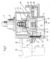
- the device switch or the switch system shown in FIGS. 1 to 4 has an essentially block-shaped switch housing which is composed of an upper housing part 1 and a lower housing part 2.
- a peg-shaped switch actuator 4 which is molded onto a carrier 5 for two contact bridges 6, which form the two movable contact pieces of the two-pole switch which are located parallel to one another.
- Carrier 5 and on the other hand is supported on the bottom 8 of the lower housing part 2.
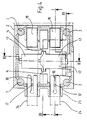
- the carrier 5 has two diametrically arranged supports 10, which project transversely to its direction of movement, for the two contact bridges 6, each of which is pressed against its support 10 by a helical compression spring 11.
- the helical compression springs 11, on the other hand, are supported on two arms 12 which are also formed in one piece with the support 5 and which, at a distance above the supports 10, protrude transversely to the direction of movement of the support 5 from its central part, which, as shown in FIG. 4, has two guide ribs 13 is provided, which extend in the direction of movement of the carrier 5 and are each guided by a groove-like guide 14 of the lower housing part 2.
- At least one of the two arms 12 carries in the region of its free end a leg spring 15, the legs of which extend from the arm 12 against the base 8 against a sliding surface of a portion of material 16 of the lower housing part 2 projecting from the base 8.
- the two sliding surfaces are provided with lugs 17 projecting against one another, which are engaged behind by the two ends of the leg spring 15 when the carrier 5 is in the closed position of the switch. This non-positive latching produces a snap effect and reduces the force that must be exerted on the switch actuator 4 after the switch is closed in order to keep it in the closed position.
- a fixed contact piece 19 with a screw connection is assigned to one end of the two contact bridges 6, which are slit conically in the longitudinal direction in their two end sections and therefore have two contact pills 18 on the underside in each end section.
- These two fixed contact pieces 19 are held by the upper housing part 1 in their receptacle provided in the lower housing part 2. They each have a longitudinal bore 20 extending transversely to the direction of movement of the carrier 5 for receiving the conductor to be connected and a transverse bore 21 accessible from outside the housing and containing a clamping screw (not shown).
- these two fixed contact pieces 19 could also be provided with a plug connection or a solder connection.
- the switch housing On the side opposite the two fixed contact pieces 19, the switch housing has two insertion openings 22 with a rectangular cross section, the longitudinal axes of which are parallel to one another and to the axes of the longitudinal bores 20.
- the insertion openings 22 are delimited in their lower part by the lower housing part 2 and in their upper part by the upper housing part 1, as a result of which they can be produced without problems.
- truncated cone-shaped projections 23 are formed concentrically with both insertion openings 22 on the outside of the housing wall having these insertion openings 22, each of which forms part of a plug connection and also extends the channel formed by the insertion openings 22.
- the cross section of the insertion openings 22 is adapted to the cross section of tab-shaped contact pieces 24 which are inserted into the interior of the housing through the insertion openings 22 only when the switch is installed in the associated device.
- the lower housing part 2 forms a support surface 25 for the material section 16 Contact piece 24.
- FIG. 1 shows that the insertion opening 22 and the support surface 25 are arranged such that the contact surface facing the contact bridge 6 lies in the same plane as the contact surface of the fixed contact piece 19 fixed in the switch housing.
- the two contact pieces 24 are formed by the end sections of a flat plug, which protrude beyond the area 26 of the associated device intended for the contact of the switch housing.
- a truncated cone-shaped depression 27 is provided in the surface 26 concentrically with the two tabs, the shape of which corresponds to that of the projections 23.
- the two plug-in contact pieces 24 are provided with a central, conical longitudinal slot 30 which extends to the free end of the contact piece 24.
- the two tongues lying next to one another are contacted by one of the two contact pills 18 of the associated end section of the contact bridge 6. Since, as shown in FIG. 1, the end sections of the contact bridge 6 adjoining a central section are bent toward the contact surfaces of the contact pieces 24, the contact pills 18 are displaced on the contact pieces 24 when the contact bridge 6 is pushed through into its extended position. This creates a self-cleaning effect on the contact surfaces.
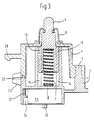
- Each of the two longitudinal slots 30 is crossed at right angles by a channel 31 provided in the lower housing part 2 and continuing into the upper housing part 1, in which a connecting wire 32 of a component 33 to be electrically conductively connected to the contact piece 24 is located, in which it is in the exemplary embodiment is a capacitor.
- the diameter of the connecting wire 32 is somewhat larger than the width of the longitudinal slot 30. Good contact is therefore achieved when the contact piece 24 is inserted through the insertion opening 22 and the connecting wire 32 enters the conical longitudinal slot 30 and expands it somewhat.
- the lower housing part 2 For receiving the component 33, the lower housing part 2 is provided with a chamber 34 which is open at the bottom and on the side walls of which hooks 35 are formed, which, as shown in FIG. 2, hold the component 33 in the chamber 34. Therefore, the assembly of the component 33 is extremely simple and inexpensive.
Landscapes
- Engineering & Computer Science (AREA)
- Manufacturing & Machinery (AREA)
- Physics & Mathematics (AREA)
- Electromagnetism (AREA)
- Push-Button Switches (AREA)
- Switch Cases, Indication, And Locking (AREA)
Claims (14)
- Système d'interrupteur, notamment pour interrupteur d'appareil, avec au moins une pièce de contact mobile (6), qui peut être déplacée, au moyen d'un organe d'actionnement d'interrupteur (4), d'une position d'ouverture à une position de fermeture, et comportant un boîtier (1, 2) qui présente au moins un logement (22, 25) pour une contre-pièce de contact (24) avec laquelle peut venir en contact la pièce de contact mobile (6) dans sa position de fermeture,
caractérisé en ce que le logement (22, 25) est réalisé non garni et est destiné à recevoir ultérieurement un corps de contact (24), qui peut être introduit à partir de l'extérieur dans le boîtier (1, 2) et qui a la forme d'une fiche plate. - Système d'interrupteur selon la revendication 1,
caractérisé en ce que le logement (22, 25) présente une ouverture d'introduction (22) qui traverse la paroi du boîtier (1, 2). - Système d'interrupteur selon la revendication 2,
caractérisé en ce que l'ouverture d'introduction (22) est réalisée sous la forme d'un passage de guidage pour le corps de contact (24). - Système d'interrupteur selon l'une des revendications 1 à 3,
caractérisé en ce que la partie du logement (22, 25), qui se trouve à l'intérieur du boîtier (1, 2), présente une surface d'appui (25), dirigée vers la pièce de contact mobile (6), pour le corps de contact insérable (24). - Système d'interrupteur selon l'une des revendications 1 à 4,
caractérisé en ce que la pièce de contact mobile (6) est réalisée sous la forme d'un pont et en ce que seul le logement (25) associé à une extrémité de pont est non garni. - Système d'interrupteur selon l'une des revendications 1 à 4,
caractérisé en ce que la pièce de contact mobile (6) est réalisée sous la forme d'un pont et en ce que les deux logements, associés à l'une et à l'autre des extrémités de pont sont non garnis. - Système d'interrupteur selon les revendications 5 et 6,
caractérisé en ce que le pont est réalisé à ressort dans le sens de son mouvement et en ce que, dans son état hors tension, les deux parties d'extrémité sont situées décalées par rapport à la partie médiane vers le logement (22, 25). - Système d'interrupteur selon l'une des revendications 5 à 7,
caractérisé en ce qu'au moins les deux parties d'extrémité du pont (6) sont constituées par deux languettes disposées avec un écartement l'une à côté de l'autre. - Système d'interrupteur selon l'une des revendications 1 à 8,
caractérisé en ce que la paroi du boîtier d'interrupteur (1, 2), qui est traversée par l'ouverture d'introduction (22), est pourvue d'un élément (23) d'un dispositif de connexion mâle-femelle consistant en une saillie (23) et en une cavité (27). - Système d'interrupteur selon la revendication 9,
caractérisé en ce que l'élément (23) du dispositif de connexion mâle-femelle, qui est prévu contre la paroi du boîtier (1, 2) est disposé selon le même axe que l'ouverture d'introduction (22). - Système d'interrupteur selon la revendication 9 ou 10,
caractérisé en ce que la paroi du boîtier (1, 2) qui présente l'élément (23) du dispositif de connexion mâle-femelle, est pourvue d'un élément (28) d'au moins un dispositif d'encliquetage, consistant en un cliquet à ressort (28) et en un cran d'arrêt (29). - Système d'interrupteur selon la revendication 11,
caractérisé en ce que le corps de contact (24) est pourvu d'au moins une fente longitudinale (30) qui s'étend jusqu'à l'extrémité venant en appui à l'intérieur du boîtier (1, 2). - Système d'interrupteur selon la revendication 12,
caractérisé par un passage (31) croisant le logement (22, 25) en un emplacement aligné sur la fente longitudinale (30), et destiné à recevoir un conducteur (32) avec lequel doit venir en contact le corps de contact (24), par serrage par les parties de matériau délimitant la fente longitudinale (30). - Système d'interrupteur selon l'une des revendications 1 à 13,
caractérisé en ce que le boîtier se compose d'au moins deux parties (1, 2) et en ce que ces parties (1, 2) sont reliées l'une à l'autre au moyen de tourillons (3), formés d'un seul tenant, qui vont en s'amincissant en direction de leur extrémité lisse, qui sont pourvus dans leur sens longitudinal de zones annulaires en forme de bourrelets, situées avec un écartement entre elles, ces tourillons pénétrant dans des passages de l'autre partie (1), conçus de manière correspondante.
Applications Claiming Priority (2)
| Application Number | Priority Date | Filing Date | Title |
|---|---|---|---|
| DE3910812A DE3910812C1 (fr) | 1989-04-04 | 1989-04-04 | |
| DE3910812 | 1989-04-04 |
Publications (2)
| Publication Number | Publication Date |
|---|---|
| EP0391049A1 EP0391049A1 (fr) | 1990-10-10 |
| EP0391049B1 true EP0391049B1 (fr) | 1995-12-13 |
Family
ID=6377790
Family Applications (1)
| Application Number | Title | Priority Date | Filing Date |
|---|---|---|---|
| EP90103217A Expired - Lifetime EP0391049B1 (fr) | 1989-04-04 | 1990-02-20 | Interrupteur, en particulier interrupteur d'appareil |
Country Status (3)
| Country | Link |
|---|---|
| US (1) | US5070221A (fr) |
| EP (1) | EP0391049B1 (fr) |
| DE (1) | DE3910812C1 (fr) |
Families Citing this family (6)
| Publication number | Priority date | Publication date | Assignee | Title |
|---|---|---|---|---|
| TW436439B (en) * | 1996-03-27 | 2001-05-28 | Honda Motor Co Ltd | Main switch of vehicle |
| FR2796733B1 (fr) * | 1999-07-19 | 2001-11-02 | Isa France Sa | Dispositif a poussoir |
| DE102007013572B4 (de) * | 2007-03-21 | 2009-06-18 | Siemens Ag | Kontaktsystem mit einer Schaltbrücke |
| DE102007015793B4 (de) * | 2007-03-30 | 2009-02-05 | Siemens Ag | Kontaktschiebereinheit für eine Schalteinheit, insbesondere einen Leistungsschalter. |
| DE102007015794B4 (de) * | 2007-03-30 | 2009-02-26 | Siemens Ag | Kontaktschiebereinheit für eine Schalteinheit, insbesondere einen Leistungsschalter, aufweisend einen Kontaktschieber und ein Schaltstück |
| DE102013203466A1 (de) | 2013-03-01 | 2014-09-04 | Zf Friedrichshafen Ag | Schalter |
Family Cites Families (11)
| Publication number | Priority date | Publication date | Assignee | Title |
|---|---|---|---|---|
| BE552342A (fr) * | 1955-11-23 | |||
| US2856492A (en) * | 1957-05-01 | 1958-10-14 | Gen Electric | Electrical contact mounting means |
| DE1097002B (de) * | 1958-01-18 | 1961-01-12 | Busch Jaeger Duerener Metall | Drucktastenschalter |
| US3542976A (en) * | 1967-08-18 | 1970-11-24 | Forest J Moray | Distributor cap and rotor combination with completely removable stationary electrode and broad contact face movable electrode |
| US3786209A (en) * | 1972-01-03 | 1974-01-15 | Molex Inc | Snap switch with pre-wired terminals |
| US4081641A (en) * | 1976-11-26 | 1978-03-28 | Cutler-Hammer, Inc. | Toggle switch with hinged split housing and insulation piercing contacts |
| DE3041470A1 (de) * | 1980-11-04 | 1982-06-09 | E. Dold & Söhne KG, 7743 Furtwangen | Taste |
| DE3118292C2 (de) * | 1981-05-08 | 1983-02-10 | Siemens AG, 1000 Berlin und 8000 München | Elektromagnetisches Relais |
| DE3209897A1 (de) * | 1982-03-18 | 1983-09-29 | Franz Kirsten Elektrotechnische Spezialfabrik, 6530 Bingen | Elektrischer schalter |
| DE3315765A1 (de) * | 1983-04-30 | 1984-10-31 | Alfred Teves Gmbh, 6000 Frankfurt | Schalterbetaetigungseinrichtung |
| DE3402372A1 (de) * | 1984-01-25 | 1985-08-01 | Doduco KG Dr. Eugen Dürrwächter, 7530 Pforzheim | Elektrisches schaltelement |
-
1989
- 1989-04-04 DE DE3910812A patent/DE3910812C1/de not_active Expired - Fee Related
-
1990
- 1990-02-20 EP EP90103217A patent/EP0391049B1/fr not_active Expired - Lifetime
- 1990-04-03 US US07/504,404 patent/US5070221A/en not_active Expired - Fee Related
Also Published As
| Publication number | Publication date |
|---|---|
| EP0391049A1 (fr) | 1990-10-10 |
| DE3910812C1 (fr) | 1990-08-23 |
| US5070221A (en) | 1991-12-03 |
Similar Documents
| Publication | Publication Date | Title |
|---|---|---|
| DE19727991C1 (de) | Elektromagnetisches Relais | |
| DE4338762C2 (de) | Druckknopfschalter | |
| EP0553694A2 (fr) | Interrupteur électrique | |
| WO1996007191A1 (fr) | Interrupteur a coulisse de levage | |
| EP0386277B1 (fr) | Borne séparatrice double | |
| EP0151692A2 (fr) | Disjoncteur de protection à courant excessif actionné par un bouton-poussoir | |
| EP0621661A2 (fr) | Socle pour appareillage électrique | |
| EP0942637A2 (fr) | Appareillage pour systèmes d'automatisation à commande électronique | |
| EP0222181A1 (fr) | Disjoncteur de surintensité | |
| EP0391049B1 (fr) | Interrupteur, en particulier interrupteur d'appareil | |
| DE19746085A1 (de) | Schalterverbindungsanordnung | |
| DE4010121C2 (fr) | ||
| DE19629563A1 (de) | Elektr. Klemme mit Überlastschutz | |
| DE2914677A1 (de) | Schiebeschalter | |
| EP0166159B1 (fr) | Interrupteur électrique | |
| EP0561317B1 (fr) | Appareil anti-déflagrant, notamment lampe | |
| DE3620105C1 (en) | Electrical contact switch | |
| DE4309132C2 (de) | Elektrischer Kontaktschalter | |
| DE2148921A1 (de) | Elektrischer Schalter | |
| DE2115732A1 (de) | Elektrisches Relais | |
| DE3324253A1 (de) | Tastenschalter | |
| DE3210033C2 (fr) | ||
| WO1998010453A1 (fr) | Dispositif electrique pour la vaporisation de substances actives | |
| EP0456984B1 (fr) | Interrupteur à fiches | |
| WO1998010456A1 (fr) | Disjoncteur de surintensite |
Legal Events
| Date | Code | Title | Description |
|---|---|---|---|
| PUAI | Public reference made under article 153(3) epc to a published international application that has entered the european phase |
Free format text: ORIGINAL CODE: 0009012 |
|
| AK | Designated contracting states |
Kind code of ref document: A1 Designated state(s): CH FR GB IT LI |
|
| 17P | Request for examination filed |
Effective date: 19910118 |
|
| 17Q | First examination report despatched |
Effective date: 19940114 |
|
| RAP1 | Party data changed (applicant data changed or rights of an application transferred) |
Owner name: KAUTT & BUX SCHALTER PRODUKTIONSGESELLSCHAFT MBH |
|
| RAP1 | Party data changed (applicant data changed or rights of an application transferred) |
Owner name: KAUTT & BUX SCHALTER PRODUKTIONSGESELLSCHAFT MBH |
|
| GRAA | (expected) grant |
Free format text: ORIGINAL CODE: 0009210 |
|
| AK | Designated contracting states |
Kind code of ref document: B1 Designated state(s): CH FR GB IT LI |
|
| ITF | It: translation for a ep patent filed |
Owner name: JACOBACCI & PERANI S.P.A. |
|
| ET | Fr: translation filed | ||
| GBT | Gb: translation of ep patent filed (gb section 77(6)(a)/1977) |
Effective date: 19960108 |
|
| REG | Reference to a national code |
Ref country code: CH Ref legal event code: NV Representative=s name: BOVARD AG PATENTANWAELTE |
|
| PLBE | No opposition filed within time limit |
Free format text: ORIGINAL CODE: 0009261 |
|
| STAA | Information on the status of an ep patent application or granted ep patent |
Free format text: STATUS: NO OPPOSITION FILED WITHIN TIME LIMIT |
|
| 26N | No opposition filed | ||
| PGFP | Annual fee paid to national office [announced via postgrant information from national office to epo] |
Ref country code: GB Payment date: 19970211 Year of fee payment: 8 |
|
| PGFP | Annual fee paid to national office [announced via postgrant information from national office to epo] |
Ref country code: CH Payment date: 19970214 Year of fee payment: 8 |
|
| PGFP | Annual fee paid to national office [announced via postgrant information from national office to epo] |
Ref country code: FR Payment date: 19970227 Year of fee payment: 8 |
|
| PG25 | Lapsed in a contracting state [announced via postgrant information from national office to epo] |
Ref country code: GB Free format text: LAPSE BECAUSE OF NON-PAYMENT OF DUE FEES Effective date: 19980220 |
|
| PG25 | Lapsed in a contracting state [announced via postgrant information from national office to epo] |
Ref country code: LI Free format text: LAPSE BECAUSE OF NON-PAYMENT OF DUE FEES Effective date: 19980228 Ref country code: FR Free format text: THE PATENT HAS BEEN ANNULLED BY A DECISION OF A NATIONAL AUTHORITY Effective date: 19980228 Ref country code: CH Free format text: LAPSE BECAUSE OF NON-PAYMENT OF DUE FEES Effective date: 19980228 |
|
| GBPC | Gb: european patent ceased through non-payment of renewal fee |
Effective date: 19980220 |
|
| REG | Reference to a national code |
Ref country code: CH Ref legal event code: PL |
|
| REG | Reference to a national code |
Ref country code: FR Ref legal event code: ST |
|
| PG25 | Lapsed in a contracting state [announced via postgrant information from national office to epo] |
Ref country code: IT Free format text: LAPSE BECAUSE OF NON-PAYMENT OF DUE FEES;WARNING: LAPSES OF ITALIAN PATENTS WITH EFFECTIVE DATE BEFORE 2007 MAY HAVE OCCURRED AT ANY TIME BEFORE 2007. THE CORRECT EFFECTIVE DATE MAY BE DIFFERENT FROM THE ONE RECORDED. Effective date: 20050220 |