EP0380687A1 - Dispositif de classement electronique simple - Google Patents
Dispositif de classement electronique simple Download PDFInfo
- Publication number
- EP0380687A1 EP0380687A1 EP89908251A EP89908251A EP0380687A1 EP 0380687 A1 EP0380687 A1 EP 0380687A1 EP 89908251 A EP89908251 A EP 89908251A EP 89908251 A EP89908251 A EP 89908251A EP 0380687 A1 EP0380687 A1 EP 0380687A1
- Authority
- EP
- European Patent Office
- Prior art keywords
- optical disk
- unit
- image information
- page
- digital image
- Prior art date
- Legal status (The legal status is an assumption and is not a legal conclusion. Google has not performed a legal analysis and makes no representation as to the accuracy of the status listed.)
- Granted
Links
Images


Classifications
-
- H—ELECTRICITY
- H04—ELECTRIC COMMUNICATION TECHNIQUE
- H04N—PICTORIAL COMMUNICATION, e.g. TELEVISION
- H04N1/00—Scanning, transmission or reproduction of documents or the like, e.g. facsimile transmission; Details thereof
- H04N1/32—Circuits or arrangements for control or supervision between transmitter and receiver or between image input and image output device, e.g. between a still-image camera and its memory or between a still-image camera and a printer device
- H04N1/32502—Circuits or arrangements for control or supervision between transmitter and receiver or between image input and image output device, e.g. between a still-image camera and its memory or between a still-image camera and a printer device in systems having a plurality of input or output devices
- H04N1/32507—Circuits or arrangements for control or supervision between transmitter and receiver or between image input and image output device, e.g. between a still-image camera and its memory or between a still-image camera and a printer device in systems having a plurality of input or output devices a plurality of input devices
- H04N1/32512—Circuits or arrangements for control or supervision between transmitter and receiver or between image input and image output device, e.g. between a still-image camera and its memory or between a still-image camera and a printer device in systems having a plurality of input or output devices a plurality of input devices of different type, e.g. internal and external devices
-
- G—PHYSICS
- G06—COMPUTING; CALCULATING OR COUNTING
- G06F—ELECTRIC DIGITAL DATA PROCESSING
- G06F16/00—Information retrieval; Database structures therefor; File system structures therefor
- G06F16/40—Information retrieval; Database structures therefor; File system structures therefor of multimedia data, e.g. slideshows comprising image and additional audio data
-
- H—ELECTRICITY
- H04—ELECTRIC COMMUNICATION TECHNIQUE
- H04N—PICTORIAL COMMUNICATION, e.g. TELEVISION
- H04N1/00—Scanning, transmission or reproduction of documents or the like, e.g. facsimile transmission; Details thereof
- H04N1/21—Intermediate information storage
- H04N1/2166—Intermediate information storage for mass storage, e.g. in document filing systems
- H04N1/217—Interfaces allowing access to a single user
- H04N1/2175—Interfaces allowing access to a single user with local image input
-
- H—ELECTRICITY
- H04—ELECTRIC COMMUNICATION TECHNIQUE
- H04N—PICTORIAL COMMUNICATION, e.g. TELEVISION
- H04N1/00—Scanning, transmission or reproduction of documents or the like, e.g. facsimile transmission; Details thereof
- H04N1/32—Circuits or arrangements for control or supervision between transmitter and receiver or between image input and image output device, e.g. between a still-image camera and its memory or between a still-image camera and a printer device
- H04N1/32502—Circuits or arrangements for control or supervision between transmitter and receiver or between image input and image output device, e.g. between a still-image camera and its memory or between a still-image camera and a printer device in systems having a plurality of input or output devices
- H04N1/32523—Circuits or arrangements for control or supervision between transmitter and receiver or between image input and image output device, e.g. between a still-image camera and its memory or between a still-image camera and a printer device in systems having a plurality of input or output devices a plurality of output devices
- H04N1/32529—Circuits or arrangements for control or supervision between transmitter and receiver or between image input and image output device, e.g. between a still-image camera and its memory or between a still-image camera and a printer device in systems having a plurality of input or output devices a plurality of output devices of different type, e.g. internal and external devices
-
- H—ELECTRICITY
- H04—ELECTRIC COMMUNICATION TECHNIQUE
- H04N—PICTORIAL COMMUNICATION, e.g. TELEVISION
- H04N2201/00—Indexing scheme relating to scanning, transmission or reproduction of documents or the like, and to details thereof
- H04N2201/0077—Types of the still picture apparatus
- H04N2201/0081—Image reader
-
- H—ELECTRICITY
- H04—ELECTRIC COMMUNICATION TECHNIQUE
- H04N—PICTORIAL COMMUNICATION, e.g. TELEVISION
- H04N2201/00—Indexing scheme relating to scanning, transmission or reproduction of documents or the like, and to details thereof
- H04N2201/0077—Types of the still picture apparatus
- H04N2201/0082—Image hardcopy reproducer
-
- H—ELECTRICITY
- H04—ELECTRIC COMMUNICATION TECHNIQUE
- H04N—PICTORIAL COMMUNICATION, e.g. TELEVISION
- H04N2201/00—Indexing scheme relating to scanning, transmission or reproduction of documents or the like, and to details thereof
- H04N2201/0077—Types of the still picture apparatus
- H04N2201/0087—Image storage device
-
- H—ELECTRICITY
- H04—ELECTRIC COMMUNICATION TECHNIQUE
- H04N—PICTORIAL COMMUNICATION, e.g. TELEVISION
- H04N2201/00—Indexing scheme relating to scanning, transmission or reproduction of documents or the like, and to details thereof
- H04N2201/0077—Types of the still picture apparatus
- H04N2201/0089—Image display device
Definitions
- This invention relates to a simple electronic file system for storing documents readily in optical disks.
- One of the means for storing documents in optical disks is the electronic file system.
- the storage of documents in optical disks by the electronic file system can contribute to space savings.
- a object of this invention is to provide a simple electronic file system which can record/store documents without using complicated registration / retrieval keys, and reproduce readily the stored documents.
- the simple electronic file system comprises a copying machine with an optical disk device including a light detecting unit for converting an optical image of a document into digital image information, an image storing unit for storing the digital image information converted from the optical image by the light detecting unit, a printer unit for printing the digital image information on a paper, an optical disk unit for recording the digital image information recorded in the optical disk contained in a replaceable (portable) optical disk cartridge, and a selection unit for selecting whether the digital image information is printed by the printer unit or not, and whether the digital image information be recorded by the optical disk unit or not; and a reproduction only optical disk including a selection unit for selecting one of the pages recorded in the optical disk in the optical cartridge to be reproduced, an optical disk unit for reading from the optical disk the digital image information of the page selected by the selection unit, an image storing unit for storing the digital image information read by the optical disk, and a flat display unit for displaying the digital image information stored in the image storing unit.
- This invention which has the above-described structure, makes it possible to record image information of a document in an optical disk in the unit of page by the copying machine with an optical disk device and reproduce in the unit of page the image information recorded in the optical disk by the reproduction only optical disk device.
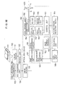
- FIG. 1 shows an example of the layout of the simple electronic file system suitably used in an office.
- the electronic file system of the office includes one copying machine with an optical disk device having an optical disk device for recording a document in an optical disk and erasing the optical disk, and a plurality of reproduction only optical disk device 30 for reproducing the document recorded in the optical disk.
- the copying machine with an optical disk device 10 is used commonly by all the office members. Respective office members operate the copying machine with an optical device 10 when they like to record a document. The structure of the copying machine with an optical device 10 will be explained below in good detail.
- the copying machine with an optical device 10 can be operated in the same way as a document is copied, so as to record a document in an optical disk.
- the reproduction only optical devices 30 are placed on the desks of the respective office members. They can operate their own devices 30 to see the contents of the documents recorded in optical disks in the same way as they look at usual files. If extra ones of the reproduction only optical devices 30 are placed in office members' houses, they will be able to do their jobs at home simply taking the optical disks home.
- a characteristic of the simple electronic file system according to this embodiment is that a document is exchanged off-line, using a compact optical disk.
- a document 2 to be recorded is recorded in an optical disk 5 by the copying machine with an optical device 10. At this time a hard copy 6 may be produced as required.
- An optical disk cartridge 4 containing an optical disk 5 with the document recorded in is kept on a desk or shelf in the usual way. Thus the optical disk takes much less space than paper copies and is free from worries about storage spaces.
- the optical disk 5 which has a capacity equivalent to about 1000 - 2000 A4 sheets is equal to the volume of one usual paper file.
- One optical disk cartridge 4 can be used as one file.
- Management data of FIG. 3 is recorded in a preset region of the optical disk as management data region.
- the management data contains the disk name DN indicating the general name of the documents recorded in the optical disk, the page addresses PA where the images of the respective pages are recorded, and the titles TL of the respective pages.
- Each page address PA contains a track number TN and a sector number SN where the associated image is recorded.
- the disk name DN and the title TL are inputted by an operator when a document is recorded in the optical disk, but they do not have to be essentially recorded, because they are for the operator's memoranda to be used when he reproduces the document. If the title TL is recorded, it is recorded in a title column on the first page of plural pages of the document.
- the page addresses PA are automatically recorded by the copying machine with an optical disk device 10 when the document is recorded. It is possible that the management data contains a data and time when the document is recorded.
- the optical disk with the management data as shown in FIG. 3 recorded in is reproduced, first the management data is read, and as shown in FIG. 4, "the disk name”, "titles” and “page numbers” are displayed. That is, the disk name is displayed at the upper portion of the displayed image, and below the disk name are sequentially displayed the "title” and "page numbers” as in contents of ordinary books. Looking at this display, the operator designates a necessary page number on the display and reproduces the necessary page.
- one optical disk can record a large volume of documents, complicated registration/retrieval keys are used.
- one optical disk has a capacity of about 1000 - 2000 A4 sheets. This small capacity yields a characteristic of this invention that the data management is based on page numbers, and the titles are used as auxiliary means for the data management.
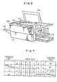
- FIGs. 5 - 7 show a first example of the copying machine with an optical disk device used in the simple electronic file system according to this embodiment.
- the copying machine with an optical disk device according to this example comprises the so-called digital copying machine for converting an image signal into a digital signal, and an optical disk device.
- the optical disk device comprises, as an ordinary digital copying machine does, a body 110, an original table 112 provided on the body 110 for mounting an original to be copied, and an original cover 114 for pressing the original on the original table 112.
- Cassettes 116 containing copy papers are loaded in the right side of the body 110, and on the left side of the body 110 is provided a copy receiving tray 118 for receiving copies.
- a cartridge receiving opening 120 at which an optical disk cartridge 4 is loaded in the body 110.
- a push button 121 is pushed to eject the loaded cartridge 4.
- a power switch 122 and a menu panel 124 for selecting the operations of an ordinary copying machine and those of an ordinary optical disk.
- a light detecting unit 130 converts the image of a document 2 to be copied on the original table 112 into digital image information.
- a linear sensor 131 reads the image of the document 2 and is moved operatively over the entire surface of the document 2.
- a preamplifier 133 amplified an image signal from the linear sensor 131. The amplified analog image signal is converted into a digital image signal.
- the digital image information of the document 2 converted by the light detection unit 130 is stored in an image memory 135.
- a selection unit 136 selects whether the digital image information stored in the image memory 135 is printed (1) on a copy paper, (2) on an optical disk or (3) both on a copy paper and an optical disk. This selection is executed by the paper/disk selecting switch 137 on the menu panel 124.
- a laser printer unit 140 prints the digital image information on a copy paper.
- a laser scanning unit 141 causes a laser beam to scan with varied intensities a photosensitive drum 142 on rotation so as to form on the photosensitive drum 142 a shade image corresponding to the digital image information outputted by the selection unit 136.
- the shade image formed on the photosensitive drum 142 is transferred onto a paper.
- the printed paper are discharged onto the copy receiving tray 118.
- the optical disk device 150 records the digital image information in the optical disk 5.
- the optical disk 5 is contained in the cartridge 4.
- the optical disk 5 is mounted on a motor 153, concurrently the magnetic field generating coil 154 coming down to a set position of the cartridge 4.
- a motor driving unit 155 drives and controls a motor 153 to rotate the optical disk 5 at a required rotation number.
- a coil driving unit 156 drives a magnetic field generating coil 154 to generate a required magnetic field.
- the digital image information outputted by the selection unit 136 to the optical disk device 150 is data-compressed by a data compression unit 157 for recording.
- the data compression is conducted by, e.g., modified READ (modified relative element address designate), an international facsimile standard.
- modified READ is detailed in Reference: R. Hunter, A. H. Robinson: International digital facsimile coding standards, Proc. IEEE, vol. 68, No. 7, pp. 854-867 (July, 1980).
- the data-compressed image information is processed, e.g. amplified, by the signal processing circuit 158 for recording in the optical disk 5.
- the signal-processed image information is recorded in the optical disk by the optical head 159.
- the optical head 159 is driven and controlled to select a track and drive without a focussing error, tracking error, etc., and the image data is recorded in the optical head 5.
- a control unit 161 controls the motor driving unit 155, the coil driving unit 156 and the optical head driving unit160 so that the image information is recorded at a required track of the optical disk.
- image information is written in the optical disk in the unit of page, and the first image of each document to be copied is recorded as Page 1 followed by the successive pages.
- this embodiment is free from complicated code inputs required by the conventional image file and records images simply in sequential order.
- the above-described management data can be inputted in the management data region of the optical disk by data input keys 168. That is, when a fresh optical disk is used, a disk name DN is inputted, and a title TL is inputted every time a document is recorded.
- the contents inputted by the data input keys 168 are displayed by the display unit 163, so that the operator can input data, checking the contents.
- Data keys are located at the central portion of the data input keys 168.
- the data keys include English letter keys from A to Z, and a space key. A part of the English letter keys can be shifted to figure keys from 0 to 9 and mark keys, such as "-", ".”, ",", "/", "*", "#”, etc.
- On the right side of the data input keys 168 are located a left scroll key, a right scroll key, a non-transform key (for transforming Hiragana's to Chinese letters), a transform/next- transform key, and a SET key.
- the English letter/Kana/figure shift key selects one key input mode out of English letter input mode, Kana input via Romanized Japanese letter mode and figure input mode. This English letter/Kana/figure shift key has successfully saved a number of keys.
- the C (one letter clear) key is for correcting an inputted letter.
- a last inputted letter is deleted by one.
- the AC (all letters clear) key deletes all the inputted letters. After the deletion, an operator resumes an input operation from the start.
- the left and the right scroll keys are for scrolling the display of an inputted disk name and titles right and left.
- the non-transform and the transform/next transform keys control the Hiragana (one Japanese script) - Chinese letter transform in inputting Kana input via Romanized Japanese letters.
- the SET key is for registering inputted letter lines.
- this data input keys 168 By operating this data input keys 168, an operator can not only input English letters, figures and marks, and Hiragana and Kana via Romanized Japanese letters, but also input Chinese letters by transforming Hiragana and Kana inputted via Romanized Japanese letters to Chinese letters.
- the control unit 161 has a page number counter 162 for indicating what ordinal number of page of the optical disk image information currently being recorded is. This page number counter 162 counts up every time image information is recorded in the optical disk 5. A content of the page number counter 162 is shown by an indicator 163 of the operation panel 124.
- a management data generating unit 169 generates management data in the format of FIG. 3, based on input contents from the data input keys 168, page addresses PA from the control unit 161, and a page number from the page number counter 162. This management data is processed by the signal processing circuit 158 to be recorded in the management data region of the optical disk 5.
- the management data written in the preset management data region of the optical disk 5 is read, and a last page number read from the management data is stored in the page number counter 162. But when the optical disk 5 has no more empty area, the indicator 163 indicates to the effect.
- the optical disk device 150 can record image information in the optical disk 5 and erase the recorded image information to initialize the optical disk. This recording and erasion are selected by operating the record/erase selecting switch 164 on the operation panel 124.
- the selection unit 136 When the paper copy mode for reproduction on a paper is selected by the paper-disk selecting switch 137, the selection unit 136 does not output the digital image information to the optical disk device 150 but to the laser printer unit 140.
- the document 2 to be copied is placed on the original table 112, and the copy switch (not shown) is pushed. Then the image information is reproduced on a paper by the laser printer unit 140 as does an ordinary copying machine.
- the selection unit 136 When the disk record mode for recording image information in the optical disk is selected by the paper/disk selection switch 137, and besides the recod mode is selected by the record/erase selection switch 164, the selection unit 136 does not output the digital image information to the laser printer 140 but to the optical disk device 150.
- a cartridge is loaded through the cartridge receiving opening 120. Then the optical disk 5 is mounted on the motor 153, and the optical disk 5 is rotated up to a required rotation number. When the rotation number of the optical disk reaches the required number, the optical head 159 reads the contents of a control track, and a last page number being currently recorded is counted by the page number counter 162.
- the indicator 163 makes an indication that the operator input the title TL of the document.
- the operator inputs the title TL as required by using the data input keys 168.
- a copy switch is (not shown) is pushed.
- the image information is read by the light detecting unit to be converted into digital image information.
- the digital image information is stored in the image memory 135.
- the selection unit 130 outputs the digital image information only to the optical disk device 150 as described above. This digital image information is data-compressed by the data compression unit 157 and further signal-processed by the signal processing circuit 158 to be outputted to the optical head 159.
- the control unit 161 instructs to the head driving unit 160 a track and a sector next to the one where a last page is recorded. Based on this instruction, the optical head 159 moves the optical head 159 so as to position on the track for the image information to be recorded in, while recording a title TL and a page address at a required position of the management data region. When this recording is completed, the control unit 161 adds 1 to the page number counter 162 to be ready for a next recording.
- the selection unit 136 When the paper copy/disk record ,mode for reproducing image data on a paper and recording the same in the optical disk is selected by the paper/disk selecting switch 137, the selection unit 136 outputs the digital image information both to the laser printer 140 and to the optical disk device 150.
- the control unit 161 controls the coil driving unit 156 and the optical head driving unit 160 so as to initialize the optical disk 5.
- erasion is conducted sequentially on all the tracks one by one. It is possible that the indicator unit 163 indicates an initialization is on. Information (e.g., "0") indicating no information is recorded in control tracks of the optical disk 5.
- this copying machine with an optical disk device enables the contents of a document to be recorded readily in an optical disk in the same way as does an ordinary copying machine, it is suitable to be used as an topical disk recording device in the simple electronic file system. Since a document can be not only copied but also recorded in an optical disk, although filing is necessary, information which is not presently necessary is stored in an optical disk, consequently with a result that information can be accumulated without papers flooding offices. Since the copying machine with an optical disk device according o this example can record and erase information, optical disks which store unnecessary information can be initialized to economically be used as fresh one.
- FIG. 8 shows a second example of the copying machine with an optical disk device.
- the constituent members of FIGs. 5 - 7 common with the first example have common reference numerals not to repeat their explanations.
- This example also comprises a digital copying machine with an optical disk and differs from the first example in that in this example image information recorded in an optical disk is read to be printed on papers.
- the optical disk device can record image information in an optical disk and erase, and also can reproduce the image information. Recording, erasion and reproduction are selected by a record/erase/reproduce selecting switch 165 on an operation panel 124. In a reproduction, the management data of an optical disk 5 is read to be displayed in a display unit 163. A page number to be reproduced is designated by figure keys or a secret key of data input keys 168 on the operation panel 124.
- Image information read from the optical disk by an optical head 159 is given a required signal processing by a signal processing circuit 158. Then the image signal is data-developed by a data-developing unit 167 to be stored in an image memory 135. The image information stored in the image memory 135 is printed on papers by a laser printing unit 140.
- This example further includes a flat display 170.
- This flat display 170 is for displaying the image information stored in the image memory 135.
- the flat display 170 is connected to the image memory 135 through an image display 171 and every image information stored in the image memory 135 is displayed. It is possible to dispose a switch on the flat display 170 for selecting whether or not the image information stored in the image memory 135 is displayed.
- the flat display 170 may be disposed at any position of the copying machine with an optical disk device, e.g., on an original cover 114, a side of a body 110 or operation panel 124.
- the flat display 170 may be be any means, such as a liquid crystal display panel, an EL display panel, a plasma display panel or others.
- the management data which is recorded in letter codes, is read to be converted into image information by a data developing unit 167, using letter patterns from a letter pattern generating unit 166, and stored in the image memory 135.
- FIG. 9 shows a third example of the copying machine with an optical disk device.
- the constituent members common with the first and the second examples have common reference numerals not to repeat their explanations.
- an image of a document to be copied is projected directly on a photosensitive drum.
- This example comprises the so-called analog copying machine, and an optical disk device.
- the copying machine with an optical device is basically an analog copying machine.
- a document 2 to be copied on an original table 112 is copied by a copying unit 180.
- the document 2 is irradiated by a light source 181.
- Its reflected image is forms on the surface of a photosensitive drum 187 through n optical system comprising mirrors 182, 183, 184, 186, 185. That is, the reflected light on the document 2 is reflected by the mirror 182 moved together with the light source 181 to have the optical path bent by the mirrors 183, 184 to be led to the mirror 185.
- the reflected image converged by the lens 185 is led by the mirror 186 to the photosensitive drum 187.
- a shade image is formed in accordance with the reflected image on the photosensitive drum 142, and this shade image is transferred onto papers by the usual method.
- the papers with the shade image transferred to are conveyed by a conveyor belt 188 to be fixed in a fixing unit 189 to be discharged onto a copy receiving tray 118.
- the mirror 186 comprises a half mirror so as to allow part of the reflected image to pass and be detected by a linear sensor 131 of a light detecting unit 130.
- a characteristic of this example is that the linear sensor 131 is inserted in the optical path of the analog copying unit 180.
- the image detected by the light detecting unit 130 is stored in an image memory 135.
- a selection unit 136 is connected to a shutter 195 through a shutter driving unit 196.
- the shutter 195 is disposed between the half mirror 186 and the photosensitive drum 187 for shielding the reflected image to the photosensitive drum 187 in accordance with whether or not to reproduce the image on papers.
- the shutter 187 may be an electrically closable shutter, such as liquid crystal or the like, or a mechanically closable shutter. Instead of disposing the shutter for shielding the reflected light, an optical image is formed on the photosensitive drum but is not reproduced on papers.
- the selection unit 136 opens the shutter 195 so as to pass the image light, while supplying an instruction to reproduce the image to the control unit (not shown) of the copying unit 180.
- a document 2 to be copied is placed on the original table 112, and then a copy switch (not shown) is pushed. Then the image is reproduced on a paper as is in an ordinary copying machine.
- the selection unit 136 When disk record mode for recording an image on an optical disk is selected by a paper/disk selecting switch 137, and besides record mode is selected by a record/erase/reproduce selecting switch 165, the selection unit 136 outputs digital image information to the optical disk device 150. At the same time, the selection unit 136 closes the shutter 195 so as not to form the image on the photosensitive drum 187, while it does not output an instruction to reproduce the image to the control unit (not shown) of the copying unit 180.
- the recording on an optical disk is the same as in the first and the second examples, and its explanation is omitted.
- the selection unit 136 opens the shutter 195, while outputting digital image information to the optical disk device 150.
- the copying machine according to this example which is an analog copying machine, can record image information on an optical disk as does a digital copying machine.
- FIGs. 10 and 11 show a fourth example of the copying machine with an optical disk device.
- the copying machine with an optical disk device comprises a copying machine 210, and an optical disk device 230 attached to a side of the copying machine 210.
- the optical disk device 230 is attached to the analog copying machine 210, but the copying machine 210 may be an analog or a digital one as long as it is usually used.
- An original table 212 for a document to be placed on is disposed on the top of this analog copying machine 210. There is provided an original cover 214 for pressing the document.
- the document 2 to be copied on the original table 212 is irradiated by a light source 216, and its reflected image is formed on the surface of a photosensitive drum 222 by an optical system comprising mirrors 217, 218, 219, 220, and lens 221. That is, the image light of the document 2 to be copied reflected by the mirror 217 moved together with the light source 216 has the optical path bent by the mirrors 218, 219 to be led to the lens 221.
- the image light converged by the lens 221 is led by the mirror 220 to the photosensitive drum 222.
- a shade image is formed on the photosensitive drum in accordance with the image light. This shade image is transferred by the usual method onto a paper taken out of a cassette 223.
- the paper with the image transferred to is conveyed by a conveyor belt 224 to a fixing unit 226 for fixing and are discharged onto a copy receiving tray 228.
- the optical disk device 230 is attached to the left side of the copying machine 210.
- a cartridge receiving opening 231 through which an optical disk cartridge 4 is inserted.
- a push button (not shown) is pushed to eject the cartridge 4.
- a linear sensor 233 for inputting the image of the document 2 is attached to the copying machine 210 immediately above a copy discharge opening 229 through which copies are discharged onto the copy receiving tray 228.
- This linear sensor 233 reads the image reproduced on a paper, and the read signal is supplied to the optical disk device 230 to be processed as will be described below.
- the linear sensor 233 is attached to the copying machine 210 immediately above the copy discharge opening 229 but it may be disposed anywhere as long as an image reproduced on a paper by the copying machine can be optically detected.
- An operation panel 234 for operating the optical disk device 230 is disposed on the top of the optical disk device 230.
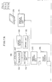
- FIG. 11 is a functional block diagram of this example.
- Common members with the first to the third examples of FIGs. 6, 8 and 9 have common reference numerals not to repeat their explanations.
- An image read by the linear sensor 233 which reads the image reproduced on a discharged paper, is converted into a digital image signal by the light detection unit 130 and outputted to an image judging unit 245.
- the image judging unit 245 a start of an image signal of a paper,based on a digital image signal converted by the light detecting unit 130. For example, when a digital signal becomes a value above a set value which is indicative of whiteness of a paper, the image judging unit 245 judges a paper has been discharged through the copy discharge opening 229 and causes an image memory 135 to store a digital signal outputted by the light detecting unit 130.
- the optical disk unit 230 records the digital image information on an optical disk.
- the optical disk is contained in a cartridge.
- the optical disk is rotated by a motor 153, and an optical head 159 records and reproduces data, and a magnetic field generating coil 154 erases data.
- Image information read from the optical disk 5 by the optical head 154 is stored in the image memory 246 via a signal processing circuit 158 and a data developing unit 167.
- the image information is displayed by a flat display 235 which is controlled by a display control unit 171, so that the image information recorded in the optical disk 5 can be reproduced on the flat display 235.
- the flat display 235 is disposed below the optical disk device 230 as shown in FIG. 10 but may be disposed anywhere.
- the flat display 235 may comprise any means, e.g., a liquid crystal panel, EL display panel, plasma display panel or others.
- a cartridge 4 is inserted through the cartridge receiving opening 231 before a document 2 to be copied is set on the original table 212. Then the optical disk 5 is mounted on a motor 153 and rotated. When the optical disk 5 reaches a set rotation number, contents of a management data region are read, and a last recorded page number is set in a page number counter 162. After the last page number has been set, the optical disk device 23 stands by until a reproduced paper comes out of the copy discharge opening 229.
- the optical image of the document 2 is read and reproduced on a paper.
- the image judging unit 245 detects the discharge of the paper, and reads and converts the optical image into digital image information.
- the digital image information is stored in the image memory 135.
- This digital image information is outputted to the optical head 159 via the data compression unit 157 and the signal processing circuit 158 to be recorded in a recording region next to the last page number.
- the control unit 161 writes the management data of this page number in a management data region while causing the counter 162 to count up by 1, and is ready for a next recording.
- FIG. 12 shows a copying machine with an optical device according to a fifth example of this invention.
- Common members with the first to the fourth examples have common reference numerals not to repeat their explanations.
- the image of a document to be copied is read from a paper with the reproduced image so as to minimize modification of the copying machine 210, while in this example, however, the image of a document to be copied is read from the optical system of the copying machine.
- the copying machine 210 is modified so that one 225 of mirrors of an optical system built in the copying machine 210 comprises a half mirror, and a linear sensor 233 is positioned so as to detect lights passing the half mirror 225.
- the linear sensor 233 is attached to the optical system of the copying machine to take out the optical image of a document to be copied. This makes it possible to obtain clearer image compared with that read from a reproduced paper.
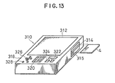
- FIGs. 13 and 14 show an example of the reproduction only optical disk device used in the simple electronic file system according to this embodiment.
- the reproduction only optical disk device has a flat display 312 for image display disposed on the top of a body 310.
- the flat display 312 comprises a liquid crystal panel, EL display panel, plasma display panel, etc.
- a cartridge receiving opening 314 is formed in the right side of the body 310.
- An optical disk cartridge 4 is inserted through the cartridge receiving opening 314.
- a push button 315 is pushed to eject the cartridge 4.
- optical disk used in the simple electric file system is an erasable rewritable optical disk, but it is preferable to make reproduction only optical disks, such as CD, CD-ROM, LD, etc., and direct read after write optical disks, which make a once recorded document permanent, reproducing so as to increase reproducing software.
- An operation panel 318 for operating this reproduction only optical disk device is provided on this side of the flat display 312.
- a display 322 provided on the right side of the ten keys 320 is used to display the management data of an optical disk, a designated page number, or the page number of a reproduced image.
- a search key 324 is provided on this side of the display 322. This search key 324 is used to search the page number of a document to be reproduced.
- a tranlation key 326 and a zoom key 328 are provided on the left side of the ten keys 320.
- the reproduction only optical disk device according to this example can enlarge or diminish a part of a reproduced image.
- the zoom key 328 is used to change a magnification for enlarging or diminishing an image.
- the tranlation key 326 is used to designate the position of a part to be enlarged or diminished.
- An optical disk 5 is contained in a cartridge 4.
- the cartridge 4 is inserted through the cartridge receiving opening 314.
- the optical disk 5 is mounted on the motor 332.
- a motor driving unit 334 controls and drives the motor 332 to rotate the optical disk at a set rotation number.
- Image information recorded in the optical disk 5 is read by an optical head 336.
- the optical head 336 is driven by an head driving unit 338 to select a track, and is controlled to read the image information with no focussing error, tracking error, etc.
- a control unit 340 controls the motor driving unit 334 and the head driving unit 338 so that the image information on a required track of the optical disk 5.
- a printer 360 is connected to the body 310 as required to make a hard copy of the image information currently displayed on the flat display 312.
- the printer may comprise one that is usually used as a terminal device of a personal computer or a facsimile, which is widely used.
- a cartridge 4 containing an optical disk 4 to be reproduced is inserted through the cartridge receiving opening 314.
- the optical disk 5 used in this example has image information recorded in the unit of page in the sequential order of pages.
- the optical disk 5 has a disk name DL and titles T of the respective documents recorded in the management data region, and the cartridge 4 has the disk name DL indicated on the outside thereof, whereby the cartridge 4 containing the optical disk 5 can be handled like a usual file or a book.
- the optical disk 5 When the cartridge 4 is inserted, the optical disk 5 is mounted on the motor 332 and starts to be rotated. When the optical disk 5 reaches a required rotation number, the optical head 336 reads the management data in the management data region, and the disk name, titles of the documents and page numbers are displayed on the flat display 332. From this displayed management data, an operator can see the contents of the optical disks 5.
- the operator points a page number of the document he wants by the ten keys 320. Then the head driving unit 338 drives the optical head 336 to read the pointed page number. When the pointed page number is larger than a last recorded page number, the display 322 displays to the effect. Then the optical head 336 reads the image information of the pointed page number, and then the image memory 350 stores the read image information via the signal processing unit 346 and the data developing unit 348. The stored image information is displayed on the flat display 131.
- the search key 324 is used to advance or retreat the page number to display the images thereof.
- the zoom key 328 or the tranlation key 326 are used as required to enlarge or diminish a part of the image.
- the printer 360 is connected to print the image on a paper.
- reproduction only optical disk device can very readily reproduce the image information recorded in an optical disk and also make hard copies thereof as required.
- This optical device has only minimum necessary functions, and thus its price can be kept lowest.
- the display device (not shown) having the flat display 312 and the operation panel 318, and a reproducing unit (not shown) for reproducing an optical disk 5 from each other and instead connect both by a line.
- the reproducing device is built in a work desk (not shown) and a connector for connection the display device is provided on the work desk, and the display device is connected to the connector as required to reproduce images. This can much contribute to the paper less system in offices.
- the optical disk device with an image scanner has the same structure as the copying machine with an optical disk device of FIG. 6 without the laser printer unit 140. That is, a document on the original table 412 is converted into digital image information by a light detecting unit 130 to be stored in an image memory 135. A linear sensor 131 is operated in the scanning direction indicated by the arrow in FIG. 17 to read the document.
- An optical disk device 150 records the digital image information stored in the image memory 135 in an optical disk 5 or erases all the recorded image information of the optical disk 5 as required.
- the digital image information read from the image memory 135 by the optical disk device 150 is data-compressed by a data compression unit 157, e.g., is data-compressed by the modified READ, international facsimile standards to be recorded in the optical disk 5.
- the optical disk device 150 has the same structure as that of FIG. 6, and it is not explained.
- a flat display (not shown) may be provided so that the image information recorded in the optical disk 5 is read by the optical disk device 150 and displayed.
- a page number to be reproduced is designated by a page number to be reproduced designating unit provided on the operation panel 124.
- the image information is read from the optical disk 5 and is subjected to a required signal processing and data development to be stored in the image memory 135.
- the flat dislay may be any display means, such as a liquid crystal panel, EL display panel, plasma display panel, or others.
- This operation is for the record mode selected by a recording/erasion selecting switch 164.
- a cartridge 122 is inserted through a cartridge receiving opening 420. Then an optical disk 5 is mounted on a motor 153, and the optical disk 5 increases its rotation number up to a set rotation number. When the optical disk 5 reaches the set rotation number, an optical head 159 reads contents of a management data region, and a last page number currently being recorded is set in a page number counter 162.
- a start switch (not shown) is- pushed. Then the image information is read by the light detection unit to be converted into digital image information. The converted image information is stored in the image memory 135. This image information is data-compressed by the data-compression unit 157, and further signal-processed by the signal processing circuit 158 to be supplied to the optical head 159.
- a control unit 161 gives a head driving unit 160 an instruction of a track number TN and a sector number SN corresponding to a page next to the last page number stored in the page number counter 162. Based on this instruction, the head driving unit 160 drives the optical head 159 so that the optical head 159 is positioned at the track and the sector for the image information to be recorded in and records the image information.
- the control unit 161 increases a page number of the page number counter 162 by 1, while writing titles TL and page addresses PA in the management data region.
- control unit 1 6 1 controls a coil driving unit 156 and the head driving unit 160 to initialize the optical disk 5.
- the initialization all the tracks of the optical disk 5 are erased sequentially one by one. It is possible to display to the effect during an initialization.
- the simple electronic file system comprises a copying machine with an optical disk device, and a reproduction only optical disk device but may further comprise an optical disk device with an image scanner for the optical disk recording.
- the second embodiment may further comprise a copying machine with an optical disk.
- erasable magneto-optical disks are used, but similarly erasable phase changeable optical disks may be used.
- Direct read after write optical disks which are not erasable and store once recorded information permanently.
- the direct read after write optical disks can store information recorded on papers compactly as does the conventional microfilm.
- disk names and document titles are used as an assistance to the page-unit retrieval.
- page numbers for retrieval, it is possible to use only page numbers for retrieval.
- an optical disk cartridge has a capacity substantially corresponding to a usual paper file volume, and the retrieval is conducted in the unit of page. This makes it possible to simplify recording of
- this simple electronic file system is usable as a ready file system suitably used in offices and at home.
Landscapes
- Engineering & Computer Science (AREA)
- Multimedia (AREA)
- Signal Processing (AREA)
- Theoretical Computer Science (AREA)
- Data Mining & Analysis (AREA)
- Databases & Information Systems (AREA)
- Physics & Mathematics (AREA)
- General Engineering & Computer Science (AREA)
- General Physics & Mathematics (AREA)
- Facsimiles In General (AREA)
- Storing Facsimile Image Data (AREA)
- Information Retrieval, Db Structures And Fs Structures Therefor (AREA)
Abstract
Applications Claiming Priority (11)
| Application Number | Priority Date | Filing Date | Title |
|---|---|---|---|
| JP63169524A JPH0218678A (ja) | 1988-07-07 | 1988-07-07 | イメージスキャナ付光ディスク装置 |
| JP169525/88 | 1988-07-07 | ||
| JP169524/88 | 1988-07-07 | ||
| JP16952588A JPH0221484A (ja) | 1988-07-07 | 1988-07-07 | 再生専用光ディスク装置 |
| JP170036/88 | 1988-07-09 | ||
| JP63170036A JP2844603B2 (ja) | 1988-07-09 | 1988-07-09 | 光ディスク装置付複写機 |
| JP63174076A JP2797324B2 (ja) | 1988-07-13 | 1988-07-13 | 複写機取付用光ディスク装置 |
| JP174076/88 | 1988-07-13 | ||
| JP63214343A JPH0263263A (ja) | 1988-08-29 | 1988-08-29 | 簡易電子ファイルシステム |
| JP214343/88 | 1988-08-29 | ||
| PCT/JP1989/000673 WO1990000779A1 (fr) | 1988-07-07 | 1989-07-05 | Dispositif de classement electronique simple |
Publications (3)
| Publication Number | Publication Date |
|---|---|
| EP0380687A1 true EP0380687A1 (fr) | 1990-08-08 |
| EP0380687A4 EP0380687A4 (en) | 1991-10-02 |
| EP0380687B1 EP0380687B1 (fr) | 1997-06-18 |
Family
ID=27528484
Family Applications (1)
| Application Number | Title | Priority Date | Filing Date |
|---|---|---|---|
| EP89908251A Expired - Lifetime EP0380687B1 (fr) | 1988-07-07 | 1989-07-05 | Dispositif de classement electronique simple |
Country Status (4)
| Country | Link |
|---|---|
| US (1) | US5150221A (fr) |
| EP (1) | EP0380687B1 (fr) |
| DE (1) | DE68928135T2 (fr) |
| WO (1) | WO1990000779A1 (fr) |
Families Citing this family (8)
| Publication number | Priority date | Publication date | Assignee | Title |
|---|---|---|---|---|
| JP2738863B2 (ja) * | 1989-06-16 | 1998-04-08 | キヤノン株式会社 | 画像送信装置 |
| JPH03276262A (ja) * | 1990-03-26 | 1991-12-06 | Ricoh Co Ltd | 電子フアイリング装置 |
| US5717442A (en) * | 1991-07-30 | 1998-02-10 | Canon Kabushiki Kaisha | Recording apparatus |
| US5708840A (en) * | 1992-06-29 | 1998-01-13 | Elonex I.P. Holdings, Ltd. | Micro personal digital assistant |
| US5584544A (en) * | 1994-10-28 | 1996-12-17 | Elf Technologies Corporation | Electronic librarian and filing system |
| US5611607A (en) * | 1994-10-28 | 1997-03-18 | Elf Technologies Corporation | Electronic librarian and filing system and method |
| JPH1115755A (ja) * | 1997-06-20 | 1999-01-22 | Matsushita Graphic Commun Syst Inc | ファクシミリ型電子メール装置 |
| JP2000172694A (ja) | 1998-12-02 | 2000-06-23 | Toshiba Corp | 画像処理システム |
Citations (4)
| Publication number | Priority date | Publication date | Assignee | Title |
|---|---|---|---|---|
| EP0145206A2 (fr) * | 1983-11-08 | 1985-06-19 | International Standard Electric Corporation | Dispositif d'affichage d'information |
| EP0051305B1 (fr) * | 1980-10-31 | 1986-03-12 | Kabushiki Kaisha Toshiba | Procédé de mise en oeuvre d'un dispositif de stockage d'information picturale |
| US4607290A (en) * | 1983-06-10 | 1986-08-19 | Kabushiki Kaisha Toshiba | Image information filing apparatus |
| EP0281415A2 (fr) * | 1987-03-05 | 1988-09-07 | Sony Corporation | Enregistrement et/ou reproduction de disques |
Family Cites Families (10)
| Publication number | Priority date | Publication date | Assignee | Title |
|---|---|---|---|---|
| JPS5776660A (en) * | 1980-10-31 | 1982-05-13 | Toshiba Corp | Recording system for variable-length picture information |
| EP0085351B1 (fr) * | 1982-01-29 | 1988-07-20 | Kabushiki Kaisha Toshiba | Dispositif d'affichage d'information d'image |
| JPS60103463A (ja) * | 1983-11-10 | 1985-06-07 | Sanyo Electric Co Ltd | 情報フアイル装置 |
| JPS62221075A (ja) * | 1986-03-20 | 1987-09-29 | Sanyo Electric Co Ltd | 情報フアイル装置 |
| JPS62288888A (ja) * | 1986-06-09 | 1987-12-15 | ケンコンピュータ株式会社 | Cd−rom用画像表示装置 |
| US4888812A (en) * | 1987-12-18 | 1989-12-19 | International Business Machines Corporation | Document image processing system |
| JP2696966B2 (ja) * | 1988-07-28 | 1998-01-14 | 東ソー株式会社 | ファクシミリ装置 |
| FR2636192B1 (fr) * | 1988-09-07 | 1992-07-24 | Sanyo Electric Co | Appareil de stockage de donnees d'image |
| JPH03196266A (ja) * | 1989-12-25 | 1991-08-27 | Toshiba Corp | 画像形成記憶装置 |
| JP3146396B2 (ja) * | 1993-03-25 | 2001-03-12 | 株式会社竹中工務店 | ソイルセメント柱列壁を利用した合成地下躯体の構築方法 |
-
1989
- 1989-07-05 EP EP89908251A patent/EP0380687B1/fr not_active Expired - Lifetime
- 1989-07-05 DE DE68928135T patent/DE68928135T2/de not_active Expired - Fee Related
- 1989-07-05 US US07/465,195 patent/US5150221A/en not_active Expired - Lifetime
- 1989-07-05 WO PCT/JP1989/000673 patent/WO1990000779A1/fr active IP Right Grant
Patent Citations (4)
| Publication number | Priority date | Publication date | Assignee | Title |
|---|---|---|---|---|
| EP0051305B1 (fr) * | 1980-10-31 | 1986-03-12 | Kabushiki Kaisha Toshiba | Procédé de mise en oeuvre d'un dispositif de stockage d'information picturale |
| US4607290A (en) * | 1983-06-10 | 1986-08-19 | Kabushiki Kaisha Toshiba | Image information filing apparatus |
| EP0145206A2 (fr) * | 1983-11-08 | 1985-06-19 | International Standard Electric Corporation | Dispositif d'affichage d'information |
| EP0281415A2 (fr) * | 1987-03-05 | 1988-09-07 | Sony Corporation | Enregistrement et/ou reproduction de disques |
Non-Patent Citations (1)
| Title |
|---|
| See also references of WO9000779A1 * |
Also Published As
| Publication number | Publication date |
|---|---|
| EP0380687B1 (fr) | 1997-06-18 |
| WO1990000779A1 (fr) | 1990-01-25 |
| DE68928135D1 (de) | 1997-07-24 |
| DE68928135T2 (de) | 1997-10-02 |
| EP0380687A4 (en) | 1991-10-02 |
| US5150221A (en) | 1992-09-22 |
Similar Documents
| Publication | Publication Date | Title |
|---|---|---|
| US4283621A (en) | Apparatus and method of storing and retrieving information | |
| US5555105A (en) | Business card image copier | |
| EP0051866B1 (fr) | Système d'emmagasinage d'information de documents | |
| EP0380687B1 (fr) | Dispositif de classement electronique simple | |
| US5930208A (en) | Method for integrating information retrieval from a plurality of dissimilar storage media including at least one optical disk | |
| JP2844603B2 (ja) | 光ディスク装置付複写機 | |
| JP4224231B2 (ja) | 画像ファイリング装置 | |
| EP0130391A2 (fr) | Procédé et appareil pour retrouver des informations sur des milieux optiques | |
| JPH0263263A (ja) | 簡易電子ファイルシステム | |
| JP2797324B2 (ja) | 複写機取付用光ディスク装置 | |
| JP2003296162A (ja) | ファイル管理方法 | |
| TW417382B (en) | Optical media access device with image scanning function | |
| JPH09116745A (ja) | 原稿読取装置および方法 | |
| JPH11232835A (ja) | データ管理装置 | |
| JP2004015619A (ja) | メモリー機能付き電子黒板装置 | |
| JPH0218678A (ja) | イメージスキャナ付光ディスク装置 | |
| JPH0346611Y2 (fr) | ||
| JPH0221484A (ja) | 再生専用光ディスク装置 | |
| JPH0351193Y2 (fr) | ||
| JPH11296548A (ja) | 識別記憶媒体表示方法及びその装置 | |
| JP2004296045A (ja) | データ記録制御方法及びデータ記録装置 | |
| JPH08340431A (ja) | 画像ファイリング装置 | |
| JPH0477868A (ja) | 画像情報の整理方法 | |
| JPH07273969A (ja) | 画像情報処理装置 | |
| JP2003069926A (ja) | 電子アルバム装置 |
Legal Events
| Date | Code | Title | Description |
|---|---|---|---|
| PUAI | Public reference made under article 153(3) epc to a published international application that has entered the european phase |
Free format text: ORIGINAL CODE: 0009012 |
|
| 17P | Request for examination filed |
Effective date: 19900313 |
|
| AK | Designated contracting states |
Kind code of ref document: A1 Designated state(s): AT BE CH DE FR GB IT LI LU NL SE |
|
| RBV | Designated contracting states (corrected) |
Designated state(s): DE FR GB NL |
|
| RAP1 | Party data changed (applicant data changed or rights of an application transferred) |
Owner name: TOSOH CORPORATION |
|
| A4 | Supplementary search report drawn up and despatched |
Effective date: 19910812 |
|
| AK | Designated contracting states |
Kind code of ref document: A4 Designated state(s): AT BE CH DE FR GB IT LI LU NL SE |
|
| 17Q | First examination report despatched |
Effective date: 19940310 |
|
| GRAG | Despatch of communication of intention to grant |
Free format text: ORIGINAL CODE: EPIDOS AGRA |
|
| GRAH | Despatch of communication of intention to grant a patent |
Free format text: ORIGINAL CODE: EPIDOS IGRA |
|
| GRAH | Despatch of communication of intention to grant a patent |
Free format text: ORIGINAL CODE: EPIDOS IGRA |
|
| GRAA | (expected) grant |
Free format text: ORIGINAL CODE: 0009210 |
|
| AK | Designated contracting states |
Kind code of ref document: B1 Designated state(s): DE FR GB NL |
|
| ET | Fr: translation filed | ||
| REF | Corresponds to: |
Ref document number: 68928135 Country of ref document: DE Date of ref document: 19970724 |
|
| PLBE | No opposition filed within time limit |
Free format text: ORIGINAL CODE: 0009261 |
|
| STAA | Information on the status of an ep patent application or granted ep patent |
Free format text: STATUS: NO OPPOSITION FILED WITHIN TIME LIMIT |
|
| 26N | No opposition filed | ||
| REG | Reference to a national code |
Ref country code: GB Ref legal event code: IF02 |
|
| PGFP | Annual fee paid to national office [announced via postgrant information from national office to epo] |
Ref country code: GB Payment date: 20040630 Year of fee payment: 16 |
|
| PGFP | Annual fee paid to national office [announced via postgrant information from national office to epo] |
Ref country code: NL Payment date: 20040704 Year of fee payment: 16 |
|
| PGFP | Annual fee paid to national office [announced via postgrant information from national office to epo] |
Ref country code: FR Payment date: 20040708 Year of fee payment: 16 |
|
| PGFP | Annual fee paid to national office [announced via postgrant information from national office to epo] |
Ref country code: DE Payment date: 20040715 Year of fee payment: 16 |
|
| PG25 | Lapsed in a contracting state [announced via postgrant information from national office to epo] |
Ref country code: GB Free format text: LAPSE BECAUSE OF NON-PAYMENT OF DUE FEES Effective date: 20050705 |
|
| PG25 | Lapsed in a contracting state [announced via postgrant information from national office to epo] |
Ref country code: NL Free format text: LAPSE BECAUSE OF NON-PAYMENT OF DUE FEES Effective date: 20060201 Ref country code: DE Free format text: LAPSE BECAUSE OF NON-PAYMENT OF DUE FEES Effective date: 20060201 |
|
| GBPC | Gb: european patent ceased through non-payment of renewal fee |
Effective date: 20050705 |
|
| PG25 | Lapsed in a contracting state [announced via postgrant information from national office to epo] |
Ref country code: FR Free format text: LAPSE BECAUSE OF NON-PAYMENT OF DUE FEES Effective date: 20060331 |
|
| NLV4 | Nl: lapsed or anulled due to non-payment of the annual fee |
Effective date: 20060201 |
|
| REG | Reference to a national code |
Ref country code: FR Ref legal event code: ST Effective date: 20060331 |