EP0372528B1 - Barren-Warmschere - Google Patents
Barren-Warmschere Download PDFInfo
- Publication number
- EP0372528B1 EP0372528B1 EP89122487A EP89122487A EP0372528B1 EP 0372528 B1 EP0372528 B1 EP 0372528B1 EP 89122487 A EP89122487 A EP 89122487A EP 89122487 A EP89122487 A EP 89122487A EP 0372528 B1 EP0372528 B1 EP 0372528B1
- Authority
- EP
- European Patent Office
- Prior art keywords
- shearing
- ring
- shear
- movable
- shearing ring
- Prior art date
- Legal status (The legal status is an assumption and is not a legal conclusion. Google has not performed a legal analysis and makes no representation as to the accuracy of the status listed.)
- Expired - Lifetime
Links
- 238000010008 shearing Methods 0.000 claims abstract description 37
- 239000002184 metal Substances 0.000 claims abstract 2
- 238000010276 construction Methods 0.000 description 2
- 238000000034 method Methods 0.000 description 2
- 238000010438 heat treatment Methods 0.000 description 1
- 238000003780 insertion Methods 0.000 description 1
- 230000037431 insertion Effects 0.000 description 1
- 238000011144 upstream manufacturing Methods 0.000 description 1
- 238000010792 warming Methods 0.000 description 1
Images

Classifications
-
- B—PERFORMING OPERATIONS; TRANSPORTING
- B23—MACHINE TOOLS; METAL-WORKING NOT OTHERWISE PROVIDED FOR
- B23D—PLANING; SLOTTING; SHEARING; BROACHING; SAWING; FILING; SCRAPING; LIKE OPERATIONS FOR WORKING METAL BY REMOVING MATERIAL, NOT OTHERWISE PROVIDED FOR
- B23D23/00—Machines or devices for shearing or cutting profiled stock
-
- Y—GENERAL TAGGING OF NEW TECHNOLOGICAL DEVELOPMENTS; GENERAL TAGGING OF CROSS-SECTIONAL TECHNOLOGIES SPANNING OVER SEVERAL SECTIONS OF THE IPC; TECHNICAL SUBJECTS COVERED BY FORMER USPC CROSS-REFERENCE ART COLLECTIONS [XRACs] AND DIGESTS
- Y10—TECHNICAL SUBJECTS COVERED BY FORMER USPC
- Y10T—TECHNICAL SUBJECTS COVERED BY FORMER US CLASSIFICATION
- Y10T83/00—Cutting
- Y10T83/404—By means to misalign aligned apertured tools
- Y10T83/412—Rectilinear relative movement only
-
- Y—GENERAL TAGGING OF NEW TECHNOLOGICAL DEVELOPMENTS; GENERAL TAGGING OF CROSS-SECTIONAL TECHNOLOGIES SPANNING OVER SEVERAL SECTIONS OF THE IPC; TECHNICAL SUBJECTS COVERED BY FORMER USPC CROSS-REFERENCE ART COLLECTIONS [XRACs] AND DIGESTS
- Y10—TECHNICAL SUBJECTS COVERED BY FORMER USPC
- Y10T—TECHNICAL SUBJECTS COVERED BY FORMER US CLASSIFICATION
- Y10T83/00—Cutting
- Y10T83/566—Interrelated tool actuating means and means to actuate work immobilizer
- Y10T83/5669—Work clamp
-
- Y—GENERAL TAGGING OF NEW TECHNOLOGICAL DEVELOPMENTS; GENERAL TAGGING OF CROSS-SECTIONAL TECHNOLOGIES SPANNING OVER SEVERAL SECTIONS OF THE IPC; TECHNICAL SUBJECTS COVERED BY FORMER USPC CROSS-REFERENCE ART COLLECTIONS [XRACs] AND DIGESTS
- Y10—TECHNICAL SUBJECTS COVERED BY FORMER USPC
- Y10T—TECHNICAL SUBJECTS COVERED BY FORMER US CLASSIFICATION
- Y10T83/00—Cutting
- Y10T83/748—With work immobilizer
- Y10T83/7487—Means to clamp work
- Y10T83/7493—Combined with, peculiarly related to, other element
- Y10T83/7513—Tool or tool support on movable clamp jaw
-
- Y—GENERAL TAGGING OF NEW TECHNOLOGICAL DEVELOPMENTS; GENERAL TAGGING OF CROSS-SECTIONAL TECHNOLOGIES SPANNING OVER SEVERAL SECTIONS OF THE IPC; TECHNICAL SUBJECTS COVERED BY FORMER USPC CROSS-REFERENCE ART COLLECTIONS [XRACs] AND DIGESTS
- Y10—TECHNICAL SUBJECTS COVERED BY FORMER USPC
- Y10T—TECHNICAL SUBJECTS COVERED BY FORMER US CLASSIFICATION
- Y10T83/00—Cutting
- Y10T83/869—Means to drive or to guide tool
- Y10T83/8752—Tool moves work to and against cooperating tool
- Y10T83/8753—With means to clamp or bind work to moving tool
Definitions
- the invention relates to a hot bar shear with the features of the preamble of claim 1.
- the fixed shear ring can be spread transversely to the shear direction in order to prevent deformation of the start of the bar in the area of the shear zone during the shearing process and to facilitate the movement of the bar in the shear rings.
- the diameter of the movable shear ring is larger than that of the fixed shear ring in its unspread state.
- the fixed shear ring In order to avoid moving the rod entering the warming shear to the front of the movable shear ring, the fixed shear ring must be spread limited to a dimension corresponding to the inner diameter of the movable shear ring. In the maximum spread state, the largest inner diameter of the fixed shear ring is aligned with the bore of the undivided movable shear ring.
- a disadvantage of this construction is the limitation of the spread to the inside diameter of the movable shear ring.
- Another disadvantage is that the rod section in the area of the undivided movable shear ring during shearing in the direction of the shear movement due to the gap between the shear ring bore and the rod surface is not supported. This leads to canting of the section and, as a result, to a correspondingly oblique shear cut.
- the invention has for its object to provide a warm shear of the type specified in the preamble of claim 1 so that a more convenient insertion of the rod to be sheared into the warm shear is possible even with more curved rods and that a deformation when shearing and a resulting oblique cut be avoided.
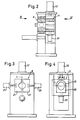
- the bar hot shear shown in FIG. 1 has a driving device 1 which conveys rods or bolts 2 from a heating system 3 through shear rings 8, 11.
- the drive device has an upper drive roller set 4 and a lower drive roller set 5, wherein the drive roller frame supporting the upper drive roller set is designed to be foldable and can be moved, for example, by a hydraulic device (not shown).
- the drive rollers are mounted horizontally displaceable on both sides in their longitudinal axis.
- the upper rollers are individually adjusted by springs 4 '(arrow b in Fig. 1).
- a block presser is made between the drive roller sets 4, 5 a rest position next to the drive rollers, which can push the bars through the shear rings 8, 11 in the direction of arrow B into a transfer device 7.
- the front fixed scissor ring 8 is firmly supported in the scissor housing 100, which guide rollers 9 are laterally upstream.
- the front shear ring 8 is adjoined by the movable shear ring 11, which is supported in a shear ring holder 102 which is vertically movable on the scissor housing 100.
- the vertical shear movement is transmitted to the shear ring holder 102 via a hydraulic system 12, in which the shear ring 11 is shifted downward from the position aligned with the fixed shear ring 8 into a position indicated by dash-dotted lines in FIG. 1.
- the diameter / length ratio of the inner bores of the shear rings 8, 11 is greater than one.
- the hot bar shears shown shear from above.
- the fixed shear ring 8 is divided into two shells 21 and 22 by a vertical parting joint running in the shear direction (FIG. 3).
- Hydraulic cylinders 25 and 26 working in opposite directions are connected to the shells 21, 22 laterally, which translationally spread the shells 21, 22 of the shear ring 8 before the bars are transported through the shear rings 8, 11.
- the movable shear ring 11 is divided into two shells 31, 32 by a horizontal parting joint running transversely to the shearing direction, of which the upper shell 31 is fixed to the housing and the lower shell can be expanded downwards by means of a hydraulic cylinder 33.
- the parting lines of the two shear rings 8, 11 thus run crosswise to one another.
- the spreading is canceled again, so that the shear ring 8, which can be expanded transversely to the shearing movement, centers the bars in the shear ring 11, so that this shear ring can also be closed without difficulty.
- this movable shear ring 11 holds the ingot in place during shearing, which improves the perpendicularity of the cut.
Landscapes
- Engineering & Computer Science (AREA)
- Mechanical Engineering (AREA)
- Shearing Machines (AREA)
- Mechanical Treatment Of Semiconductor (AREA)
- Metal Rolling (AREA)
- Crystals, And After-Treatments Of Crystals (AREA)
- Forging (AREA)
- Joining Of Building Structures In Genera (AREA)
- Scissors And Nippers (AREA)
Priority Applications (1)
| Application Number | Priority Date | Filing Date | Title |
|---|---|---|---|
| AT89122487T ATE88395T1 (de) | 1988-12-09 | 1989-12-06 | Barren-warmschere. |
Applications Claiming Priority (2)
| Application Number | Priority Date | Filing Date | Title |
|---|---|---|---|
| DE3841584A DE3841584C1 (enExample) | 1988-12-09 | 1988-12-09 | |
| DE3841584 | 1988-12-09 |
Publications (3)
| Publication Number | Publication Date |
|---|---|
| EP0372528A2 EP0372528A2 (de) | 1990-06-13 |
| EP0372528A3 EP0372528A3 (en) | 1990-11-22 |
| EP0372528B1 true EP0372528B1 (de) | 1993-04-21 |
Family
ID=6368849
Family Applications (1)
| Application Number | Title | Priority Date | Filing Date |
|---|---|---|---|
| EP89122487A Expired - Lifetime EP0372528B1 (de) | 1988-12-09 | 1989-12-06 | Barren-Warmschere |
Country Status (5)
| Country | Link |
|---|---|
| US (1) | US5062336A (enExample) |
| EP (1) | EP0372528B1 (enExample) |
| AT (1) | ATE88395T1 (enExample) |
| CA (1) | CA2003883A1 (enExample) |
| DE (2) | DE3841584C1 (enExample) |
Families Citing this family (17)
| Publication number | Priority date | Publication date | Assignee | Title |
|---|---|---|---|---|
| JP2741351B2 (ja) * | 1994-11-09 | 1998-04-15 | 旭サナック株式会社 | 圧造機における素材切断装置 |
| DE19605724C2 (de) * | 1996-02-16 | 2001-04-12 | Mannesmann Sachs Ag | Schneideinrichtung zum Schneiden von metallischem Bandmaterial |
| KR100459976B1 (ko) * | 1999-10-15 | 2004-12-03 | 하테부르 움포름마쉬넨 아크티엔게젤샤프트 | 전단장치를 구비한 성형 기계 |
| US7073420B2 (en) * | 2003-04-29 | 2006-07-11 | Hsung Huei Industrial Co., Ltd. | Hydraulic cutting device for cutting a raw aluminum material |
| US8545405B2 (en) * | 2008-04-23 | 2013-10-01 | Therataxis, Llc | Device, methods, and control for sonic guidance of molecules and other material utilizing time-reversal acoustics |
| CN101941096B (zh) * | 2010-08-26 | 2012-07-04 | 袁正敏 | 环缸环刀式精剪机 |
| JP5753452B2 (ja) * | 2011-07-01 | 2015-07-22 | 株式会社万陽 | 切断クランプ装置を備えた切断機 |
| CN104889499B (zh) * | 2015-06-23 | 2018-01-30 | 仁化县博世铝业有限公司 | 一种铝型材安全切割机 |
| CN105149674B (zh) * | 2015-09-22 | 2018-09-25 | 江苏江顺精密机电设备有限公司 | 铝棒剪切机 |
| CN106737999B (zh) * | 2016-11-18 | 2018-10-30 | 重庆市臻憬科技开发有限公司 | 一种切削机进料装置 |
| WO2019002638A1 (es) * | 2017-06-30 | 2019-01-03 | Neotecman,S.L. | Sistema y método de corte para máquina de conformado en caliente para estampación de piezas de metal no ferroso |
| CN107284047A (zh) * | 2017-07-04 | 2017-10-24 | 毛利英 | 一种信箱装置 |
| CN108817500A (zh) * | 2018-06-27 | 2018-11-16 | 麻城市中达精密机械有限公司 | 棒料剪切装置及料头料尾自动分选方法 |
| JP7192174B2 (ja) * | 2018-11-09 | 2022-12-20 | 旭サナック株式会社 | 線材切断装置 |
| CN110899850A (zh) * | 2019-12-10 | 2020-03-24 | 章丘市鑫达锻造有限公司 | 一种提高效率的圆钢下料方法及其使用该方法的下料机 |
| CN113305339A (zh) * | 2021-06-15 | 2021-08-27 | 浙江精勇精锻机械有限公司 | 一种低油压式棒料快速自动切断机 |
| CN114871488A (zh) * | 2022-05-30 | 2022-08-09 | 瑞安市华大液压机械厂 | 环抱剪切设备 |
Family Cites Families (9)
| Publication number | Priority date | Publication date | Assignee | Title |
|---|---|---|---|---|
| US2380898A (en) * | 1942-10-22 | 1945-07-31 | Atristain Martha Pimentel | Cutting device |
| US3348441A (en) * | 1964-03-27 | 1967-10-24 | American Metal Climax Inc | Apparatus for cutting billets by means of apertured dies |
| US3552253A (en) * | 1968-08-26 | 1971-01-05 | Am Forge Inc | Bar shear apparatus |
| JPS4987935A (enExample) * | 1972-12-27 | 1974-08-22 | ||
| CH577865A5 (enExample) * | 1973-05-05 | 1976-07-30 | Hatebur Umformmaschinen Ag | |
| US3972257A (en) * | 1974-12-12 | 1976-08-03 | Lazar Jr John Daniel | Bar stock shear |
| DE2604418C2 (de) * | 1976-02-05 | 1982-06-03 | Friedrich Wilhelm Dipl.-Ing. 5600 Wuppertal Elhaus | Barren-Warmschere |
| WO1981000687A1 (en) * | 1979-09-04 | 1981-03-19 | Slugger Corp | Method and apparatus for shearing bars,billets and other elongated stock |
| GB8705096D0 (en) * | 1987-03-05 | 1987-04-08 | Mechatherm Eng Ltd | Shearing |
-
1988
- 1988-12-09 DE DE3841584A patent/DE3841584C1/de not_active Expired - Fee Related
-
1989
- 1989-11-24 CA CA002003883A patent/CA2003883A1/en not_active Abandoned
- 1989-12-05 US US07/446,043 patent/US5062336A/en not_active Expired - Fee Related
- 1989-12-06 AT AT89122487T patent/ATE88395T1/de active
- 1989-12-06 EP EP89122487A patent/EP0372528B1/de not_active Expired - Lifetime
- 1989-12-06 DE DE8989122487T patent/DE58904147D1/de not_active Expired - Fee Related
Also Published As
| Publication number | Publication date |
|---|---|
| US5062336A (en) | 1991-11-05 |
| EP0372528A3 (en) | 1990-11-22 |
| EP0372528A2 (de) | 1990-06-13 |
| DE3841584C1 (enExample) | 1990-02-01 |
| DE58904147D1 (de) | 1993-05-27 |
| CA2003883A1 (en) | 1990-06-09 |
| ATE88395T1 (de) | 1993-05-15 |
Similar Documents
| Publication | Publication Date | Title |
|---|---|---|
| EP0372528B1 (de) | Barren-Warmschere | |
| EP0629456B1 (de) | Vorrichtung zum Herstellen von Hohlkörpern | |
| EP0287848B1 (de) | Längsteil-Streifenschere | |
| DE19940744B4 (de) | Radialpresse | |
| EP0463201A1 (de) | Stahlstranggiessanlage mit mechanischer Entfernungseinrichtung für Sauerstoffschneidbärte | |
| EP0323607A2 (de) | Langschmiedemaschine zum Schmieden von runden oder scharfkantigen Stangen | |
| DE2013554A1 (de) | Verfahren zum Walzen von Präzisionswerkstücken und Anlage zum Durchführen des Verfahrens | |
| DE2713501A1 (de) | Fliegend arbeitende schere, insbesondere pendelschere | |
| EP0172449A2 (de) | Führungseinrichtung an den Giessbändern einer Doppelbandstranggiesskokille | |
| EP0118739B1 (de) | Rohrbiegeanlage | |
| DE2554358A1 (de) | Verfahren und schneidvorrichtung zum trennen eines stranges mit mindestens einem brenner beim stranggiessen von stahl | |
| DE1941094C3 (de) | Abspannvorrichtung eines Strebförderers in der Strecke | |
| DE3044350C2 (de) | Schere in einer Bandschweißanlage zum Beschneiden von zwei Bandenden | |
| DE2643260C2 (de) | Ortsbewegliche, tragbare Vorrichtung zum Abarbeiten von Schweißgutüberständen bei der Schienen-Verbindungsschweißung | |
| DE2742732A1 (de) | Vorrichtung zum kuppeln eines dorns mit einem dorntragschlitten bei einem walz- und lochwalzgeruest | |
| DE1627321A1 (de) | Schneidvorrichtung fuer Band-,Streifen- oder Plattenmaterial | |
| DE585415C (de) | Metallrohr- und Strangpresse | |
| DE2908498A1 (de) | Maschine zum walzen von gewinde auf bolzen u.dgl. | |
| DE2339269C3 (de) | Schere zum Zerschneiden von Stahlprofilen | |
| DE2340340A1 (de) | Laengsteilschere fuer walzbleche, insbesondere grobbleche | |
| EP0484782B1 (de) | Stauchpresse zur Reduktion der Breite von Brammen in Warmbreitband-Vorstrassen | |
| DE19709033A1 (de) | Beschneideeinrichtung | |
| DE2300628C2 (de) | Ringschmiedepressenanlage zum Schmieden großer Ringe, insbesondere zum Aufweiten von Ringen | |
| DE2717621C2 (de) | Schrottschere | |
| DE1924029C3 (de) | Metallblock-Lochpresse |
Legal Events
| Date | Code | Title | Description |
|---|---|---|---|
| PUAI | Public reference made under article 153(3) epc to a published international application that has entered the european phase |
Free format text: ORIGINAL CODE: 0009012 |
|
| AK | Designated contracting states |
Kind code of ref document: A2 Designated state(s): AT BE CH DE ES FR IT LI LU NL |
|
| PUAL | Search report despatched |
Free format text: ORIGINAL CODE: 0009013 |
|
| RHK1 | Main classification (correction) |
Ipc: B23D 23/00 |
|
| AK | Designated contracting states |
Kind code of ref document: A3 Designated state(s): AT BE CH DE ES FR IT LI LU NL |
|
| 17P | Request for examination filed |
Effective date: 19901221 |
|
| 17Q | First examination report despatched |
Effective date: 19920203 |
|
| GRAA | (expected) grant |
Free format text: ORIGINAL CODE: 0009210 |
|
| AK | Designated contracting states |
Kind code of ref document: B1 Designated state(s): AT BE CH DE ES FR IT LI LU NL |
|
| PG25 | Lapsed in a contracting state [announced via postgrant information from national office to epo] |
Ref country code: NL Effective date: 19930421 Ref country code: BE Effective date: 19930421 |
|
| REF | Corresponds to: |
Ref document number: 88395 Country of ref document: AT Date of ref document: 19930515 Kind code of ref document: T |
|
| ITF | It: translation for a ep patent filed | ||
| REF | Corresponds to: |
Ref document number: 58904147 Country of ref document: DE Date of ref document: 19930527 |
|
| ET | Fr: translation filed | ||
| PG25 | Lapsed in a contracting state [announced via postgrant information from national office to epo] |
Ref country code: ES Free format text: LAPSE BECAUSE OF FAILURE TO SUBMIT A TRANSLATION OF THE DESCRIPTION OR TO PAY THE FEE WITHIN THE PRESCRIBED TIME-LIMIT Effective date: 19930801 |
|
| NLV1 | Nl: lapsed or annulled due to failure to fulfill the requirements of art. 29p and 29m of the patents act | ||
| PLBE | No opposition filed within time limit |
Free format text: ORIGINAL CODE: 0009261 |
|
| STAA | Information on the status of an ep patent application or granted ep patent |
Free format text: STATUS: NO OPPOSITION FILED WITHIN TIME LIMIT |
|
| 26N | No opposition filed | ||
| PGFP | Annual fee paid to national office [announced via postgrant information from national office to epo] |
Ref country code: DE Payment date: 19940421 Year of fee payment: 5 |
|
| EPTA | Lu: last paid annual fee | ||
| PGFP | Annual fee paid to national office [announced via postgrant information from national office to epo] |
Ref country code: CH Payment date: 19941214 Year of fee payment: 6 |
|
| PGFP | Annual fee paid to national office [announced via postgrant information from national office to epo] |
Ref country code: ES Payment date: 19941223 Year of fee payment: 6 |
|
| PGFP | Annual fee paid to national office [announced via postgrant information from national office to epo] |
Ref country code: LU Payment date: 19950101 Year of fee payment: 6 |
|
| PG25 | Lapsed in a contracting state [announced via postgrant information from national office to epo] |
Ref country code: DE Effective date: 19950901 |
|
| PG25 | Lapsed in a contracting state [announced via postgrant information from national office to epo] |
Ref country code: LU Free format text: LAPSE BECAUSE OF NON-PAYMENT OF DUE FEES Effective date: 19951206 |
|
| PGFP | Annual fee paid to national office [announced via postgrant information from national office to epo] |
Ref country code: FR Payment date: 19951212 Year of fee payment: 7 |
|
| PGFP | Annual fee paid to national office [announced via postgrant information from national office to epo] |
Ref country code: AT Payment date: 19951213 Year of fee payment: 7 |
|
| PG25 | Lapsed in a contracting state [announced via postgrant information from national office to epo] |
Ref country code: LI Effective date: 19951231 Ref country code: CH Effective date: 19951231 |
|
| REG | Reference to a national code |
Ref country code: CH Ref legal event code: PL |
|
| PG25 | Lapsed in a contracting state [announced via postgrant information from national office to epo] |
Ref country code: AT Effective date: 19961206 |
|
| PG25 | Lapsed in a contracting state [announced via postgrant information from national office to epo] |
Ref country code: FR Effective date: 19970829 |
|
| REG | Reference to a national code |
Ref country code: FR Ref legal event code: ST |
|
| PG25 | Lapsed in a contracting state [announced via postgrant information from national office to epo] |
Ref country code: IT Free format text: LAPSE BECAUSE OF NON-PAYMENT OF DUE FEES;WARNING: LAPSES OF ITALIAN PATENTS WITH EFFECTIVE DATE BEFORE 2007 MAY HAVE OCCURRED AT ANY TIME BEFORE 2007. THE CORRECT EFFECTIVE DATE MAY BE DIFFERENT FROM THE ONE RECORDED. Effective date: 20051206 |