EP0368871B1 - Selbsttätiger türschliesser - Google Patents
Selbsttätiger türschliesser Download PDFInfo
- Publication number
- EP0368871B1 EP0368871B1 EP88904918A EP88904918A EP0368871B1 EP 0368871 B1 EP0368871 B1 EP 0368871B1 EP 88904918 A EP88904918 A EP 88904918A EP 88904918 A EP88904918 A EP 88904918A EP 0368871 B1 EP0368871 B1 EP 0368871B1
- Authority
- EP
- European Patent Office
- Prior art keywords
- cylinder
- door
- damping
- closer
- damping cylinder
- Prior art date
- Legal status (The legal status is an assumption and is not a legal conclusion. Google has not performed a legal analysis and makes no representation as to the accuracy of the status listed.)
- Expired - Lifetime
Links
- 238000013016 damping Methods 0.000 claims abstract description 27
- 239000012530 fluid Substances 0.000 claims description 3
- 238000011144 upstream manufacturing Methods 0.000 claims 1
- 238000004519 manufacturing process Methods 0.000 abstract description 5
- 238000005553 drilling Methods 0.000 description 5
- 238000010276 construction Methods 0.000 description 2
- 238000000034 method Methods 0.000 description 2
- 238000003466 welding Methods 0.000 description 2
- 230000015572 biosynthetic process Effects 0.000 description 1
- 230000006835 compression Effects 0.000 description 1
- 238000007906 compression Methods 0.000 description 1
- 239000000463 material Substances 0.000 description 1
- 239000002184 metal Substances 0.000 description 1
- 238000007789 sealing Methods 0.000 description 1
- 239000000779 smoke Substances 0.000 description 1
- 230000008646 thermal stress Effects 0.000 description 1
Images


Classifications
-
- E—FIXED CONSTRUCTIONS
- E05—LOCKS; KEYS; WINDOW OR DOOR FITTINGS; SAFES
- E05F—DEVICES FOR MOVING WINGS INTO OPEN OR CLOSED POSITION; CHECKS FOR WINGS; WING FITTINGS NOT OTHERWISE PROVIDED FOR, CONCERNED WITH THE FUNCTIONING OF THE WING
- E05F3/00—Closers or openers with braking devices, e.g. checks; Construction of pneumatic or liquid braking devices
- E05F3/04—Closers or openers with braking devices, e.g. checks; Construction of pneumatic or liquid braking devices with liquid piston brakes
- E05F3/10—Closers or openers with braking devices, e.g. checks; Construction of pneumatic or liquid braking devices with liquid piston brakes with a spring, other than a torsion spring, and a piston, the axes of which are the same or lie in the same direction
-
- E—FIXED CONSTRUCTIONS
- E05—LOCKS; KEYS; WINDOW OR DOOR FITTINGS; SAFES
- E05F—DEVICES FOR MOVING WINGS INTO OPEN OR CLOSED POSITION; CHECKS FOR WINGS; WING FITTINGS NOT OTHERWISE PROVIDED FOR, CONCERNED WITH THE FUNCTIONING OF THE WING
- E05F3/00—Closers or openers with braking devices, e.g. checks; Construction of pneumatic or liquid braking devices
- E05F3/04—Closers or openers with braking devices, e.g. checks; Construction of pneumatic or liquid braking devices with liquid piston brakes
- E05F3/12—Special devices controlling the circulation of the liquid, e.g. valve arrangement
-
- E—FIXED CONSTRUCTIONS
- E05—LOCKS; KEYS; WINDOW OR DOOR FITTINGS; SAFES
- E05Y—INDEXING SCHEME ASSOCIATED WITH SUBCLASSES E05D AND E05F, RELATING TO CONSTRUCTION ELEMENTS, ELECTRIC CONTROL, POWER SUPPLY, POWER SIGNAL OR TRANSMISSION, USER INTERFACES, MOUNTING OR COUPLING, DETAILS, ACCESSORIES, AUXILIARY OPERATIONS NOT OTHERWISE PROVIDED FOR, APPLICATION THEREOF
- E05Y2201/00—Constructional elements; Accessories therefor
- E05Y2201/20—Brakes; Disengaging means; Holders; Stops; Valves; Accessories therefor
- E05Y2201/252—Type of friction
- E05Y2201/254—Fluid or viscous friction
-
- E—FIXED CONSTRUCTIONS
- E05—LOCKS; KEYS; WINDOW OR DOOR FITTINGS; SAFES
- E05Y—INDEXING SCHEME ASSOCIATED WITH SUBCLASSES E05D AND E05F, RELATING TO CONSTRUCTION ELEMENTS, ELECTRIC CONTROL, POWER SUPPLY, POWER SIGNAL OR TRANSMISSION, USER INTERFACES, MOUNTING OR COUPLING, DETAILS, ACCESSORIES, AUXILIARY OPERATIONS NOT OTHERWISE PROVIDED FOR, APPLICATION THEREOF
- E05Y2900/00—Application of doors, windows, wings or fittings thereof
- E05Y2900/10—Application of doors, windows, wings or fittings thereof for buildings or parts thereof
- E05Y2900/13—Type of wing
- E05Y2900/132—Doors
Definitions
- the invention relates to an automatic door closer according to the preamble of claim 1. It is preferably a pinion-type door closer or crank-mechanism door closer according to the German industrial standard 18263. These door closers are used for fire protection doors, smoke protection doors and apartment doors.
- the energy required for self-closing is usually stored in a helical compression spring.
- the closing movement is dampened by hydraulic throttling.
- the damping piston which is displaceable from the outside, is arranged in the damping cylinder between radial throttle bores, which are connected to one another via an overflow channel, each of which connects a pressure space in the cylinder in front of the piston to the unpressurized space behind the piston via a throttle valve.
- the damping cylinder which simultaneously forms the housing of the door closer, is made in one piece, either as a die-cast part or as a section of a corresponding continuous cast hollow profile, preferably made of a light metal.
- the manufacture of such cylinders is difficult with regard to the tightly tolerated mount for the damping piston and the necessary long overflow channel and the throttle bores and requires special machine tools.
- the mount for the damping piston must be manufactured with high tolerance accuracy.
- the overflow channel which usually runs parallel to the damping piston in the one-piece cylinder, is particularly difficult to manufacture, and can be connected precisely from the outside or from the inside to the throttle bores arranged transversely.
- the object of the invention is to simplify an automatic door closer of the type mentioned in production terms.
- prefabricated pipe sections can be used as damping cylinders which are already sufficiently tightly tolerated with regard to the piston holder.
- the formation of the overflow channel between the outside of the tubular damping cylinder and the tightly fitted cover element avoids the previously required complicated bores in the damping cylinder.
- the cover elements which adapt to the outer shape of the tubular damping cylinder require only a very small increase in the outer diameter of the cylinder.
- a groove is welded on the outside of the tubular damping cylinder as a cover element with an outwardly pronounced cavity which is open towards the tubular hollow cylinder and which forms the overflow channel with the tubular hollow cylinder.
- Covering elements of this type can be attached to the tubular hollow cylinder using a known welding method, without thermal stress affecting the tightly tolerated cylinder receptacle.
- the invention also includes the proposal according to claim 3 to form the respective cover element in one piece with the subsequent throttle valve housing, so that in this case the possible two individual elements are placed together in a sealed manner on the damping cylinder and can preferably be fastened by a welded connection.
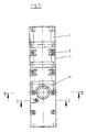
- FIGS. 1-6 Two half-shells 1 and 2 form a cylinder receptacle in which a tubular hollow cylinder 6 forming the door closer housing is positioned and sealed in a form-fitting manner is included.
- the housing shells lie against each other in the division level 4.
- the number 3 indicates an additional cover shown in dashed lines.
- the two half-shells 1 and 2 are braced against one another via the screw connections 5.
- the tubular hollow cylinder 6 is closed at the end by the plug 66.
- a hydraulic piston 8 which is displaceable from the outside via a corresponding connecting rod or the like, not shown, separates a pressure chamber 61 from a non-pressurized chamber 62.
- two radial throttle bores 63 and 64 open into the pressure chamber 61 open into an overflow channel 21 in the half-shell 2 parallel to the cylinder axis.
- this overflow channel 21 is molded openly into the hollow hollow cylinder 6 in the cylinder receptacle of the half-shell 2.
- a seal receptacle 22 is formed around the overflow channel 21 and a molded seal 9 is inserted into it.
- Other types of seals can also be used here.
- the bores 23 and 12 shown in FIGS. 5 and 6, which are used to pass the drive linkage, are also surrounded by a seal receptacle 24.
- the seals 10 to be arranged therein can be seen in FIG. 5.
- the tubular hollow cylinder 6 is also excluded at the corresponding points.
- the hydraulic piston 8 is displaced in the direction of the sealing plug 66.
- the hydraulic fluid flows out of the pressure chamber 61 through the throttle bores 63 and 64 via the overflow channel 21 Throttle valve 7 and from this valve to the unpressurized space 62.
- the throttle valve 7 projects with its valve cone 71 into the bore 65 formed as a valve seat on the hollow cylinder 6.
- the throttle valve 7 is inserted radially into the half-shell 2 with the seal 62 and is adjustable from the outside.
- the hollow cylinder 6 is positioned between the half-shells 1 and 2.
- a cam 11 provided in the half-shell 1 engages in a corresponding recess 67 on the outside of the hollow cylinder 6.
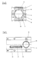
- FIGS. 7-10 A less technically complex construction of a door closer housing is shown in FIGS. 7-10.
- the housing is formed by the tubular hollow cylinder 106, which can be a section of a prefabricated tube with a tightly tolerated inner diameter.
- the hollow cylinder forms the interior for the hydraulic piston 108.
- the two throttle bores 163 and 164 are provided in the radial direction.
- the overflow channel 121 is arranged on the outside of the hollow cylinder 6. It is formed by the channel 102, which is fastened tightly on the tubular hollow cylinder 106 using a suitable welding method.
- the throttle valve 107 or its valve housing is attached to the channel 102. This housing can also be fastened with a welded connection or a suitable other connection.
- the overflow channel 121 formed connects the throttle bores 163 and 164 with the bore 165 to the unpressurized space.
- the valve cone of the throttle valve 107 acts against this bore 165.
- bushings 112 and 123 are arranged transversely to the axis on the hollow cylinder 106.
- the tabs 103 serve to fasten the housing.
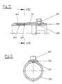
- FIGS. 11 and 2 show the tubular hollow cylinder 206 of an automatic door closer, in which a groove-like depression is formed on the outside in the region of the throttle bores 263, 264 and 265 in order to form the overflow channel 221.
- a partially shell-shaped cover element 202 is placed in a sealed manner over this depression and is preferably fastened with a welded connection.
- the cover element 202 is already connected to the housing of the throttle valve 207 in the same material.
Landscapes
- Closing And Opening Devices For Wings, And Checks For Wings (AREA)
- Power-Operated Mechanisms For Wings (AREA)
- Fluid-Damping Devices (AREA)
- Lock And Its Accessories (AREA)
- Liquid Crystal (AREA)
- Vending Machines For Individual Products (AREA)
- Elevator Door Apparatuses (AREA)
Priority Applications (1)
| Application Number | Priority Date | Filing Date | Title |
|---|---|---|---|
| AT88904918T ATE69856T1 (de) | 1987-06-13 | 1988-06-10 | Selbsttaetiger tuerschliesser. |
Applications Claiming Priority (4)
| Application Number | Priority Date | Filing Date | Title |
|---|---|---|---|
| DE3719883 | 1987-06-13 | ||
| DE3719883 | 1987-06-13 | ||
| DE3735010 | 1987-10-16 | ||
| DE19873735010 DE3735010A1 (de) | 1987-06-13 | 1987-10-16 | Tuerschliesser mit hydraulischer daempfung |
Publications (2)
| Publication Number | Publication Date |
|---|---|
| EP0368871A1 EP0368871A1 (de) | 1990-05-23 |
| EP0368871B1 true EP0368871B1 (de) | 1991-11-27 |
Family
ID=25856659
Family Applications (1)
| Application Number | Title | Priority Date | Filing Date |
|---|---|---|---|
| EP88904918A Expired - Lifetime EP0368871B1 (de) | 1987-06-13 | 1988-06-10 | Selbsttätiger türschliesser |
Country Status (8)
| Country | Link |
|---|---|
| US (1) | US5090089A (OSRAM) |
| EP (1) | EP0368871B1 (OSRAM) |
| JP (1) | JPH02503811A (OSRAM) |
| AT (1) | ATE69856T1 (OSRAM) |
| AU (1) | AU1808888A (OSRAM) |
| DE (4) | DE3735010A1 (OSRAM) |
| FI (1) | FI91911C (OSRAM) |
| WO (1) | WO1988009860A1 (OSRAM) |
Cited By (1)
| Publication number | Priority date | Publication date | Assignee | Title |
|---|---|---|---|---|
| US8225458B1 (en) | 2001-07-13 | 2012-07-24 | Hoffberg Steven M | Intelligent door restraint |
Families Citing this family (21)
| Publication number | Priority date | Publication date | Assignee | Title |
|---|---|---|---|---|
| DE4002889C5 (de) * | 1990-02-01 | 2005-11-10 | Geze Gmbh | Türschließer |
| GB9106245D0 (en) * | 1991-03-23 | 1991-05-08 | Newman Tonks Eng | Door closer |
| US6120385A (en) * | 1994-09-27 | 2000-09-19 | Nemeckay; Stephen A. | Golf training device |
| US5538299A (en) * | 1994-09-27 | 1996-07-23 | Nemeckay; Stephen A. | Housing and securing device |
| USD387971S (en) * | 1995-02-13 | 1997-12-23 | Dexter Automatic Products Company | Combined housing and securing device |
| DE19857297C1 (de) * | 1998-12-14 | 2000-07-06 | Dorma Gmbh & Co Kg | Türschließer |
| RU2183242C1 (ru) * | 2001-06-01 | 2002-06-10 | Амурский государственный университет | Устройство для закрывания двери |
| US7316096B2 (en) | 2004-06-30 | 2008-01-08 | Yale Security Inc. | Door operator |
| US20060021189A1 (en) * | 2004-07-30 | 2006-02-02 | Johnson Loring M | Door closer |
| CA2698634C (en) | 2007-04-24 | 2014-02-11 | Yale Security Inc. | Door closer assembly |
| DE102007059707B4 (de) * | 2007-12-10 | 2022-02-17 | Eco Schulte Gmbh & Co. Kg | Türschließergehäuse mit schräg angeordnetem Ventil |
| IT1395306B1 (it) * | 2009-08-06 | 2012-09-05 | Gosio Dianora | Una cerniera per celle frigorifere, cancelli pedonali o similari |
| US9163446B2 (en) * | 2010-03-17 | 2015-10-20 | Yale Security Inc. | Door control apparatus |
| US8564235B2 (en) | 2010-04-16 | 2013-10-22 | Yale Security Inc. | Self-adjusting door closer |
| US8779713B2 (en) | 2010-04-16 | 2014-07-15 | Yale Security Inc. | Door closer with dynamically adjustable latch region parameters |
| US8773237B2 (en) | 2010-04-16 | 2014-07-08 | Yale Security Inc. | Door closer with teach mode |
| US8415902B2 (en) | 2010-04-16 | 2013-04-09 | Yale Security Inc. | Door closer with calibration mode |
| US8547046B2 (en) | 2010-04-16 | 2013-10-01 | Yale Security Inc. | Door closer with self-powered control unit |
| US8527101B2 (en) | 2010-04-16 | 2013-09-03 | Yale Security Inc. | Door closer assembly |
| DE102013112453A1 (de) * | 2013-11-13 | 2015-05-13 | Dorma Deutschland Gmbh | Obentürschließer |
| US10633903B2 (en) * | 2016-05-13 | 2020-04-28 | Colcom Group S.P.A. | Hinge for the rotatable movement of a door, a shutter or the like |
Family Cites Families (15)
| Publication number | Priority date | Publication date | Assignee | Title |
|---|---|---|---|---|
| DE667522C (de) * | 1936-12-19 | 1938-11-12 | Walter Graichen | Tuerschliesser mit Fluessigkeitschemmung |
| GB639376A (en) * | 1948-07-17 | 1950-06-28 | Eric George Quibell | Improvements in door closers |
| DE826849C (de) * | 1949-12-15 | 1952-01-07 | Yale & Towne Mfg Co | Tuerschliessergehaeuse |
| DE931696C (de) * | 1952-04-06 | 1955-08-16 | Gunther Sasse | Tuerschliesser mit einer Schliesserachse, auf welche ein unter Federspannung stehendes Zugorgan und eine hydraulische Bremseinrichtung einwirken |
| US3079629A (en) * | 1961-05-04 | 1963-03-05 | Ronan And Kunzl Inc | Hydraulically retarded door closer |
| DE1584167A1 (de) * | 1965-12-30 | 1970-03-19 | Merayo Revuelta Jose Luis | Hydraulisch gedaempfter Tuerschliesser |
| GB1214132A (en) * | 1966-11-21 | 1970-12-02 | Brent Metal Works Ltd | Improved door-closer mechanism |
| US3426382A (en) * | 1967-09-27 | 1969-02-11 | Schlage Lock Co | Housing for door closing and checking mechanism |
| US3584331A (en) * | 1969-06-13 | 1971-06-15 | Rixson Inc | Hydraulic door checking mechanism |
| US3574886A (en) * | 1969-07-10 | 1971-04-13 | Norris Industries | Position control hydraulic snubber |
| JPS4935547U (OSRAM) * | 1972-06-27 | 1974-03-29 | ||
| FI194773A7 (OSRAM) * | 1973-06-15 | 1974-12-16 | Veli Jaakko Saajos | |
| FR2311919A1 (fr) * | 1975-05-21 | 1976-12-17 | Baumgartner & Co Hans | Dispositif de commande equipe d'un dispositif de freinage hydraulique pour portes |
| US4115897A (en) * | 1977-10-11 | 1978-09-26 | Eaton Corporation | Zero force hold open door closer |
| US4601502A (en) * | 1985-05-06 | 1986-07-22 | Dyke James R Van | Door stop assembly |
-
1987
- 1987-10-16 DE DE19873735010 patent/DE3735010A1/de not_active Withdrawn
-
1988
- 1988-06-10 DE DE88DE8800347D patent/DE3890451D2/de not_active Expired
- 1988-06-10 AU AU18088/88A patent/AU1808888A/en not_active Abandoned
- 1988-06-10 DE DE3890451A patent/DE3890451C1/de not_active Expired - Lifetime
- 1988-06-10 WO PCT/DE1988/000347 patent/WO1988009860A1/de not_active Ceased
- 1988-06-10 AT AT88904918T patent/ATE69856T1/de not_active IP Right Cessation
- 1988-06-10 JP JP63504669A patent/JPH02503811A/ja active Pending
- 1988-06-10 DE DE8888904918T patent/DE3866547D1/de not_active Expired - Lifetime
- 1988-06-10 EP EP88904918A patent/EP0368871B1/de not_active Expired - Lifetime
- 1988-06-10 US US07/445,696 patent/US5090089A/en not_active Expired - Fee Related
-
1989
- 1989-12-12 FI FI895939A patent/FI91911C/fi not_active IP Right Cessation
Cited By (2)
| Publication number | Priority date | Publication date | Assignee | Title |
|---|---|---|---|---|
| US8225458B1 (en) | 2001-07-13 | 2012-07-24 | Hoffberg Steven M | Intelligent door restraint |
| US9121217B1 (en) | 2001-07-13 | 2015-09-01 | Steven M. Hoffberg | Intelligent door restraint |
Also Published As
| Publication number | Publication date |
|---|---|
| AU1808888A (en) | 1989-01-04 |
| JPH02503811A (ja) | 1990-11-08 |
| DE3866547D1 (de) | 1992-01-09 |
| FI895939A0 (fi) | 1989-12-12 |
| DE3890451C1 (OSRAM) | 1990-04-26 |
| EP0368871A1 (de) | 1990-05-23 |
| FI91911C (fi) | 1994-08-25 |
| FI91911B (fi) | 1994-05-13 |
| ATE69856T1 (de) | 1991-12-15 |
| US5090089A (en) | 1992-02-25 |
| WO1988009860A1 (fr) | 1988-12-15 |
| DE3890451D2 (en) | 1989-08-17 |
| DE3735010A1 (de) | 1988-12-22 |
Similar Documents
| Publication | Publication Date | Title |
|---|---|---|
| EP0368871B1 (de) | Selbsttätiger türschliesser | |
| DE3623787A1 (de) | Gasfeder mit endlagendaempfung | |
| DE2933590A1 (de) | Gasfeder mit hydraulischer oder hydropneumatischer enddaempfung | |
| EP0733822B1 (de) | Mit Fluid gefüllte Zylinder-Kolbenstangen-Einheit, insbesondere Gasfeder | |
| DE3900927A1 (de) | Pneumatisches oder hydropneumatisches verstellelement | |
| EP0757742B1 (de) | Selbsttätiger türschliesser und verfahren zur montage desselben | |
| DE3342404C2 (OSRAM) | ||
| DE4342883C2 (de) | Hydraulischer, regelbarer Schwingungsdämpfer für Kraftfahrzeuge | |
| DE4213809C1 (OSRAM) | ||
| DE19504207C2 (de) | Arbeitszylinder | |
| DE19842840A1 (de) | Dämpfungsventil | |
| DE19815313A1 (de) | Fahrstabilisator für Kraftfahrzeuge | |
| DE2801950A1 (de) | Explosionsschutz- und flammenrueckschlagschutz-ventil | |
| CH666731A5 (de) | Kolben, insbesondere fuer hydraulische oder pneumatische arbeitszylinder. | |
| EP0669469B1 (de) | Fluidisch betätigbarer Drehantrieb | |
| EP1293633A2 (de) | Türschliesser | |
| DE10158123B4 (de) | Endlagengedämpfter Druckmittelzylinder | |
| DE3933624C2 (OSRAM) | ||
| EP1428962A1 (de) | Kolben-Zylinder-Einheit | |
| DE3900817A1 (de) | Gasfeder | |
| DE2458321B2 (de) | Stellventil | |
| EP0080565A2 (de) | Einrichtung zur Endabbremsung des Arbeitskolbens eines doppeltwirkenden Arbeitszylinders | |
| DE4031761C2 (de) | Hydropneumatisches Aggregat | |
| DE69627925T2 (de) | Drehantrieb | |
| DE4031760A1 (de) | Daempfkraftveraenderbarer hydraulischer schwingungsdaempfer |
Legal Events
| Date | Code | Title | Description |
|---|---|---|---|
| PUAI | Public reference made under article 153(3) epc to a published international application that has entered the european phase |
Free format text: ORIGINAL CODE: 0009012 |
|
| 17P | Request for examination filed |
Effective date: 19890906 |
|
| AK | Designated contracting states |
Kind code of ref document: A1 Designated state(s): AT BE CH DE FR GB IT LI LU NL SE |
|
| 17Q | First examination report despatched |
Effective date: 19910508 |
|
| GRAA | (expected) grant |
Free format text: ORIGINAL CODE: 0009210 |
|
| AK | Designated contracting states |
Kind code of ref document: B1 Designated state(s): AT BE CH DE FR GB IT LI LU NL SE |
|
| REF | Corresponds to: |
Ref document number: 69856 Country of ref document: AT Date of ref document: 19911215 Kind code of ref document: T |
|
| ET | Fr: translation filed | ||
| REF | Corresponds to: |
Ref document number: 3866547 Country of ref document: DE Date of ref document: 19920109 |
|
| ITF | It: translation for a ep patent filed | ||
| GBT | Gb: translation of ep patent filed (gb section 77(6)(a)/1977) | ||
| PG25 | Lapsed in a contracting state [announced via postgrant information from national office to epo] |
Ref country code: LU Free format text: LAPSE BECAUSE OF NON-PAYMENT OF DUE FEES Effective date: 19920630 |
|
| PGFP | Annual fee paid to national office [announced via postgrant information from national office to epo] |
Ref country code: NL Payment date: 19920630 Year of fee payment: 5 |
|
| PGFP | Annual fee paid to national office [announced via postgrant information from national office to epo] |
Ref country code: BE Payment date: 19920708 Year of fee payment: 5 |
|
| PGFP | Annual fee paid to national office [announced via postgrant information from national office to epo] |
Ref country code: CH Payment date: 19920720 Year of fee payment: 5 |
|
| PLBE | No opposition filed within time limit |
Free format text: ORIGINAL CODE: 0009261 |
|
| STAA | Information on the status of an ep patent application or granted ep patent |
Free format text: STATUS: NO OPPOSITION FILED WITHIN TIME LIMIT |
|
| 26N | No opposition filed | ||
| PG25 | Lapsed in a contracting state [announced via postgrant information from national office to epo] |
Ref country code: DE Effective date: 19930302 |
|
| PG25 | Lapsed in a contracting state [announced via postgrant information from national office to epo] |
Ref country code: LI Effective date: 19930630 Ref country code: CH Effective date: 19930630 Ref country code: BE Effective date: 19930630 |
|
| BERE | Be: lapsed |
Owner name: E C O SCHULTE G.M.B.H. & CO. K.G. Effective date: 19930630 |
|
| PG25 | Lapsed in a contracting state [announced via postgrant information from national office to epo] |
Ref country code: NL Effective date: 19940101 |
|
| NLV4 | Nl: lapsed or anulled due to non-payment of the annual fee | ||
| REG | Reference to a national code |
Ref country code: CH Ref legal event code: PL |
|
| PGFP | Annual fee paid to national office [announced via postgrant information from national office to epo] |
Ref country code: AT Payment date: 19940620 Year of fee payment: 7 |
|
| PGFP | Annual fee paid to national office [announced via postgrant information from national office to epo] |
Ref country code: SE Payment date: 19940621 Year of fee payment: 7 |
|
| EAL | Se: european patent in force in sweden |
Ref document number: 88904918.5 |
|
| PG25 | Lapsed in a contracting state [announced via postgrant information from national office to epo] |
Ref country code: AT Effective date: 19950610 |
|
| PG25 | Lapsed in a contracting state [announced via postgrant information from national office to epo] |
Ref country code: SE Effective date: 19950611 |
|
| EUG | Se: european patent has lapsed |
Ref document number: 88904918.5 |
|
| PGFP | Annual fee paid to national office [announced via postgrant information from national office to epo] |
Ref country code: GB Payment date: 19970414 Year of fee payment: 10 |
|
| PGFP | Annual fee paid to national office [announced via postgrant information from national office to epo] |
Ref country code: FR Payment date: 19970616 Year of fee payment: 10 |
|
| PG25 | Lapsed in a contracting state [announced via postgrant information from national office to epo] |
Ref country code: GB Free format text: LAPSE BECAUSE OF NON-PAYMENT OF DUE FEES Effective date: 19980610 |
|
| GBPC | Gb: european patent ceased through non-payment of renewal fee |
Effective date: 19980610 |
|
| PG25 | Lapsed in a contracting state [announced via postgrant information from national office to epo] |
Ref country code: FR Free format text: LAPSE BECAUSE OF NON-PAYMENT OF DUE FEES Effective date: 19990226 |
|
| REG | Reference to a national code |
Ref country code: FR Ref legal event code: ST |
|
| PG25 | Lapsed in a contracting state [announced via postgrant information from national office to epo] |
Ref country code: IT Free format text: LAPSE BECAUSE OF NON-PAYMENT OF DUE FEES Effective date: 20050610 |