EP0368871B1 - Selbsttätiger türschliesser - Google Patents
Selbsttätiger türschliesser Download PDFInfo
- Publication number
- EP0368871B1 EP0368871B1 EP88904918A EP88904918A EP0368871B1 EP 0368871 B1 EP0368871 B1 EP 0368871B1 EP 88904918 A EP88904918 A EP 88904918A EP 88904918 A EP88904918 A EP 88904918A EP 0368871 B1 EP0368871 B1 EP 0368871B1
- Authority
- EP
- European Patent Office
- Prior art keywords
- cylinder
- door
- damping
- closer
- damping cylinder
- Prior art date
- Legal status (The legal status is an assumption and is not a legal conclusion. Google has not performed a legal analysis and makes no representation as to the accuracy of the status listed.)
- Expired - Lifetime
Links
Images


Classifications
-
- E—FIXED CONSTRUCTIONS
- E05—LOCKS; KEYS; WINDOW OR DOOR FITTINGS; SAFES
- E05F—DEVICES FOR MOVING WINGS INTO OPEN OR CLOSED POSITION; CHECKS FOR WINGS; WING FITTINGS NOT OTHERWISE PROVIDED FOR, CONCERNED WITH THE FUNCTIONING OF THE WING
- E05F3/00—Closers or openers with braking devices, e.g. checks; Construction of pneumatic or liquid braking devices
- E05F3/04—Closers or openers with braking devices, e.g. checks; Construction of pneumatic or liquid braking devices with liquid piston brakes
- E05F3/10—Closers or openers with braking devices, e.g. checks; Construction of pneumatic or liquid braking devices with liquid piston brakes with a spring, other than a torsion spring, and a piston, the axes of which are the same or lie in the same direction
-
- E—FIXED CONSTRUCTIONS
- E05—LOCKS; KEYS; WINDOW OR DOOR FITTINGS; SAFES
- E05F—DEVICES FOR MOVING WINGS INTO OPEN OR CLOSED POSITION; CHECKS FOR WINGS; WING FITTINGS NOT OTHERWISE PROVIDED FOR, CONCERNED WITH THE FUNCTIONING OF THE WING
- E05F3/00—Closers or openers with braking devices, e.g. checks; Construction of pneumatic or liquid braking devices
- E05F3/04—Closers or openers with braking devices, e.g. checks; Construction of pneumatic or liquid braking devices with liquid piston brakes
- E05F3/12—Special devices controlling the circulation of the liquid, e.g. valve arrangement
-
- E—FIXED CONSTRUCTIONS
- E05—LOCKS; KEYS; WINDOW OR DOOR FITTINGS; SAFES
- E05Y—INDEXING SCHEME RELATING TO HINGES OR OTHER SUSPENSION DEVICES FOR DOORS, WINDOWS OR WINGS AND DEVICES FOR MOVING WINGS INTO OPEN OR CLOSED POSITION, CHECKS FOR WINGS AND WING FITTINGS NOT OTHERWISE PROVIDED FOR, CONCERNED WITH THE FUNCTIONING OF THE WING
- E05Y2201/00—Constructional elements; Accessories therefore
- E05Y2201/20—Brakes; Disengaging means, e.g. clutches; Holders, e.g. locks; Stops; Accessories therefore
- E05Y2201/252—Brakes; Disengaging means, e.g. clutches; Holders, e.g. locks; Stops; Accessories therefore characterised by type of friction
- E05Y2201/254—Fluid or viscous friction
-
- E—FIXED CONSTRUCTIONS
- E05—LOCKS; KEYS; WINDOW OR DOOR FITTINGS; SAFES
- E05Y—INDEXING SCHEME RELATING TO HINGES OR OTHER SUSPENSION DEVICES FOR DOORS, WINDOWS OR WINGS AND DEVICES FOR MOVING WINGS INTO OPEN OR CLOSED POSITION, CHECKS FOR WINGS AND WING FITTINGS NOT OTHERWISE PROVIDED FOR, CONCERNED WITH THE FUNCTIONING OF THE WING
- E05Y2900/00—Application of doors, windows, wings or fittings thereof
- E05Y2900/10—Application of doors, windows, wings or fittings thereof for buildings or parts thereof
- E05Y2900/13—Application of doors, windows, wings or fittings thereof for buildings or parts thereof characterised by the type of wing
- E05Y2900/132—Doors
Definitions
- the invention relates to an automatic door closer according to the preamble of claim 1. It is preferably a pinion-type door closer or crank-mechanism door closer according to the German industrial standard 18263. These door closers are used for fire protection doors, smoke protection doors and apartment doors.
- the energy required for self-closing is usually stored in a helical compression spring.
- the closing movement is dampened by hydraulic throttling.
- the damping piston which is displaceable from the outside, is arranged in the damping cylinder between radial throttle bores, which are connected to one another via an overflow channel, each of which connects a pressure space in the cylinder in front of the piston to the unpressurized space behind the piston via a throttle valve.
- the damping cylinder which simultaneously forms the housing of the door closer, is made in one piece, either as a die-cast part or as a section of a corresponding continuous cast hollow profile, preferably made of a light metal.
- the manufacture of such cylinders is difficult with regard to the tightly tolerated mount for the damping piston and the necessary long overflow channel and the throttle bores and requires special machine tools.
- the mount for the damping piston must be manufactured with high tolerance accuracy.
- the overflow channel which usually runs parallel to the damping piston in the one-piece cylinder, is particularly difficult to manufacture, and can be connected precisely from the outside or from the inside to the throttle bores arranged transversely.
- the object of the invention is to simplify an automatic door closer of the type mentioned in production terms.
- prefabricated pipe sections can be used as damping cylinders which are already sufficiently tightly tolerated with regard to the piston holder.
- the formation of the overflow channel between the outside of the tubular damping cylinder and the tightly fitted cover element avoids the previously required complicated bores in the damping cylinder.
- the cover elements which adapt to the outer shape of the tubular damping cylinder require only a very small increase in the outer diameter of the cylinder.
- a groove is welded on the outside of the tubular damping cylinder as a cover element with an outwardly pronounced cavity which is open towards the tubular hollow cylinder and which forms the overflow channel with the tubular hollow cylinder.
- Covering elements of this type can be attached to the tubular hollow cylinder using a known welding method, without thermal stress affecting the tightly tolerated cylinder receptacle.
- the invention also includes the proposal according to claim 3 to form the respective cover element in one piece with the subsequent throttle valve housing, so that in this case the possible two individual elements are placed together in a sealed manner on the damping cylinder and can preferably be fastened by a welded connection.
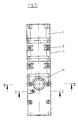
- FIGS. 1-6 Two half-shells 1 and 2 form a cylinder receptacle in which a tubular hollow cylinder 6 forming the door closer housing is positioned and sealed in a form-fitting manner is included.
- the housing shells lie against each other in the division level 4.
- the number 3 indicates an additional cover shown in dashed lines.
- the two half-shells 1 and 2 are braced against one another via the screw connections 5.
- the tubular hollow cylinder 6 is closed at the end by the plug 66.
- a hydraulic piston 8 which is displaceable from the outside via a corresponding connecting rod or the like, not shown, separates a pressure chamber 61 from a non-pressurized chamber 62.
- two radial throttle bores 63 and 64 open into the pressure chamber 61 open into an overflow channel 21 in the half-shell 2 parallel to the cylinder axis.
- this overflow channel 21 is molded openly into the hollow hollow cylinder 6 in the cylinder receptacle of the half-shell 2.
- a seal receptacle 22 is formed around the overflow channel 21 and a molded seal 9 is inserted into it.
- Other types of seals can also be used here.
- the bores 23 and 12 shown in FIGS. 5 and 6, which are used to pass the drive linkage, are also surrounded by a seal receptacle 24.
- the seals 10 to be arranged therein can be seen in FIG. 5.
- the tubular hollow cylinder 6 is also excluded at the corresponding points.
- the hydraulic piston 8 is displaced in the direction of the sealing plug 66.
- the hydraulic fluid flows out of the pressure chamber 61 through the throttle bores 63 and 64 via the overflow channel 21 Throttle valve 7 and from this valve to the unpressurized space 62.
- the throttle valve 7 projects with its valve cone 71 into the bore 65 formed as a valve seat on the hollow cylinder 6.
- the throttle valve 7 is inserted radially into the half-shell 2 with the seal 62 and is adjustable from the outside.
- the hollow cylinder 6 is positioned between the half-shells 1 and 2.
- a cam 11 provided in the half-shell 1 engages in a corresponding recess 67 on the outside of the hollow cylinder 6.
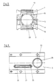
- FIGS. 7-10 A less technically complex construction of a door closer housing is shown in FIGS. 7-10.
- the housing is formed by the tubular hollow cylinder 106, which can be a section of a prefabricated tube with a tightly tolerated inner diameter.
- the hollow cylinder forms the interior for the hydraulic piston 108.
- the two throttle bores 163 and 164 are provided in the radial direction.
- the overflow channel 121 is arranged on the outside of the hollow cylinder 6. It is formed by the channel 102, which is fastened tightly on the tubular hollow cylinder 106 using a suitable welding method.
- the throttle valve 107 or its valve housing is attached to the channel 102. This housing can also be fastened with a welded connection or a suitable other connection.
- the overflow channel 121 formed connects the throttle bores 163 and 164 with the bore 165 to the unpressurized space.
- the valve cone of the throttle valve 107 acts against this bore 165.
- bushings 112 and 123 are arranged transversely to the axis on the hollow cylinder 106.
- the tabs 103 serve to fasten the housing.
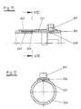
- FIGS. 11 and 2 show the tubular hollow cylinder 206 of an automatic door closer, in which a groove-like depression is formed on the outside in the region of the throttle bores 263, 264 and 265 in order to form the overflow channel 221.
- a partially shell-shaped cover element 202 is placed in a sealed manner over this depression and is preferably fastened with a welded connection.
- the cover element 202 is already connected to the housing of the throttle valve 207 in the same material.
Description
- Die Erfindung betrifft einen selbsttätigen Türschließer nach dem Oberbegriff des Anspruches 1. Es handelt sich dabei vorzugsweise um Zahntrieb-Türschließer oder Kurbeltrieb-Türschließer nach der Deutschen Industrienorm 18263. Diese Türschließer werden verwendet für Feuerschutztüren, Rauchschutztüren und Wohnungsabschlußtüren. Die notwendige Energie für die Selbstschließung wird in der Regel in einer Schraubendruckfeder gespeichert. Die Schließbewegung wird gedämpft durch eine hydraulische Drosselung. Dabei ist in dem Dämpfungszylinder der von außen gesteuert verschiebbare Dämpfungskolben zwischen radialen Drosselbohrungen angeorndet, die über einen Überströmkanal miteinander verbunden sind, der jeweils einen Druckraum im Zylinder vor dem Kolben mit dem drucklosen Raum hinter dem Kolben über ein Drosselventil verbindet.
- Bei den bekannten Türschließern dieser Art ist der Dämpfungszylinder, der gleichzeitig das Gehäuse des Türschließers bildet, einteilig ausgeführt, entweder als Druckgußteil oder als Abschnitt eines entsprechenden Stranggußhohlprofiles, vorzugsweise aus einem Leichtmetall. Die Fertigung solcher Zylinder ist bezüglich der engtolerierten Aufnahme für den Dämpfungskolben und des notwendigen langen Überströmkanals sowie der Drosselbohrungen schwierig und erfordert Spezialwerkzeugmaschinen. Infolge der hohen auftretenden Drücke muß die Fertigung der Aufnahme für den Dämpfungskolben mit hoher Toleranzgenauigkeit erfolgen. Fertigungsschwierigkeiten bereitet insbesondere der in der Regel parallel zum Dämpfungskolben im einteiligen Zylinder verlaufende Überströmkanal, der von außen oder von innen mit den quer angeordneten Drosselbohrungen exakt zu verbinden ist.
- In der DE-PS 931 696 ist bereits vorgeschlagen worden, an einem speziellen Dämpfungszylinder, der der Dämpfung des in einem gesonderten Gehäuse untergebrachten Türschließer dient, außen eine rohrartige Leitung als Überströmkanal anzuordnen. Eine solche außenliegende Überströmleitung erweist sich jedoch als störend.
- Aus der DE-PS 826 849 ist es bekannt, an dem als Gehäuse ausgebildeten Dämpfungszylinder eines selbsttätigen Türschließers einen Ansatz anzugießen mit einer eingegossenen Überströmleitung. Als Zylinderaufnahme sind in dem als Gußkörper ausgebildeten Gehäuse rohrförmige Abschnitte ebenfalls eingegossen. Eine Fertigung solcher Türschließergehäuse erweist sich als aufwendig und schwierig. Sie erfordert das genaue Einrichten der Rohrteile in der Gießform. Das entstehende Gehäuse selbst ist relativ voluminös.
- Bei einem selbsttätigen Türschließer nach der DE-A 1 584 167 ist es bekannt, an dem Dämpfungszylinder konzentrisch einen Hohlzylinder anzuordnen. Der gebildete Ringspalt dient als Überströmkanal für die Hydraulikflüssigkeit. Der relativ große Querschnitt des Ringspaltes läßt jedoch eine ausreichende Drosselsteuerung nicht zu. Der Konstruktionsaufwand ist hoch.
- Die Aufgabe der Erfindung besteht darin, einen selbsttätigen Türschließer der eingangs genannten Art fertigungstechnisch zu vereinfachen.
- Gelöst wird die Erfindungsaufgabe mit einem Türschließer mit sämtlichen Merkmalen des Anspruches 1.
- Nach dem erfindungsgemäßen Vorschlag lassen sich konfektionierte Rohrabschnitte als Dämpfungszylinder verwenden, die bezüglich der Kolbenaufnahme bereits ausreichend engtoleriert sind. Durch die Ausbildung des Überströmkanals zwischen der Außenseite des rohrförmigen Dämpfungszylinders und dem dicht aufgesetzten Abdeckelement werden die bisher notwendigen komplizierten Bohrungen im Dämpfungszylinder vermieden. Die sich der Außenform des rohrförmigen Dämpfungszylinders anpassenden Abdeckelemente erfordern nur eine sehr geringe Vergrößerung des Außendurchmessers des Zylinders.
- Nach einer bevorzugten Ausführungsform der Erfindung gemäß Anspruch 2 ist außen auf dem rohrförmigen Dämpfungszylinder eine Rinne als Abdeckelement aufgeschweißt mit einem nach außen ausgeprägten, zum rohrförmigen Hohlzylinder hin offenen Hohlraum, der mit dem rohrförmigen Hohlzylinder den Überströmkanal bildet. Derartige Abdeckelemente lassen sich mit einem bekannten Schweißverfahren am rohrförmigen Hohlzylinder bebefestigen, ohne daß Wärmebeanspruchungen die engtolerierte Zylinderaufnahme beeinflussen.
- Zur Erfindung gehört auch der Vorschlag gemäß Anspruch 3, das jeweilige Abdeckelement einteilig mit dem anschließenden Drosselventilgehäuse auszubilden, so daß in diesem Fall die möglichen beiden Einzelelemente gemeinsam am Dämpfungszylinder abgedichtet aufgesetzt werden und vorzügsweise durch eine Schweißverbindung befestigt werden können.
- Anhand abgebildeter Ausführungsbeispiele wird die Erfindung im folgenden näher erläutert. Es zeigen:
- Figur 1 die Vorderansicht des Gehäuses eines Türschließers in Schalenbauweise,
- Figur 2 die Draufsicht auf das Gehäuse in Figur 1,
- Figur 3 einen Schnitt nach der Linie I - I in Figur 2,
- Figur 4 einen Schnitt nach der Linie III - III in Figur 3,
- Figur 5 einen Schnitt nach der Linie II - II in Figur 2,
- Figur 6 einen Schnitt nach der Linie IV - IV in Figur 4 ohne den rohrförmigen Hohlzylinder,
- Figur 7 eine Draufsicht auf ein weiteres Türschließergehäuse,
- Figur 8 einen Schnitt nach der Linie V - V in Figur 7
- Figur 9 einen Teilschnitt nach der Linie VI - VI in Figur 7,
- Figur 10 einen Teilschnitt nach der Linie VII - VII in Figur 7,
- Figur 11 einen Teillängsschnitt durch ein weiteres Türschließergehäuse im Bereich des gebildeten Überströmkanals und
- Figur 12 einen Schnitt nach der Linie VIII - VIII in Figur 11.
- Zunächst wird auf die Figuren 1 - 6 Bezug genommen. Zwei Halbschalen 1 und 2 bilden eine Zylinderaufnahme, in der positioniert und abgedichtet formschlüssig ein das Türschließergehäuse bildender rohrförmiger Hohlzylinder 6 aufgenommen ist. Die Gehäuseschalen liegen dabei in der Teilungsebene 4 gegeneinander. Mit der Ziffer 3 ist eine gestrichelt dargestellte zusätzliche Abdeckung angedeutet. Die beiden Halbschalen 1 und 2 werden über die Schraubverbindungen 5 gegeneinander verspannt.
- Der rohrförmige Hohlzylinder 6 ist endseitig durch den Stopfen 66 verschlossen. In dem Hohlzylinder 6 trennt ein Hydraulikkolben 8, der von außen über ein entsprechendes nicht dargestelltes Verbindungsgestänge oder dergleichen verschiebbar ist, einen Druckraum 61 von einem drucklosen Raum 62. Wie Figur 4 zeigt, münden in den Druckraum 61 zwei radiale Drosselbohrungen 63 und 64, die in einen zur Zylinderachse parallelen Überströmkanal 21 in der Halbschale 2 münden.
- Wie aus den Figuren 4 und 6 ersichtlich, ist dieser Überströmkanal 21 zum rohrförmigen Hohlzylinder 6 hin nutartig offen in der Zylinderaufnahme der Halbschale 2 eingeformt. Um den Überströmkanal 21 herum ist eine Dichtungsaufnahme 22 eingeformt, in er eine Formdichtung 9 eingelegt ist. Andere Dichtungsarten sind an dieser Stelle ebenfalls einsetzbar.
- Die in Figur 5 und 6 ersichtlichen Bohrungen 23 und 12, die der Durchführung des Antriebsgestänges dienen, sind ebenfalls von einer Dichtungsaufnahme 24 umgeben. Die darin anzuordnenden Dichtungen 10 sind in Figur 5 erkennbar. Zur Einführung dieses Gestänges, beispielsweise eines Zahntriebes, ist der rohrförmige Hohlzylinder 6 an den entsprechenden Stellen ebenfalls ausgenommen.
- Während der Schließbewegung einer mit einem solchen Türschließer ausgestatteten Tür wird der Hydraulikkolben 8 in Richtung auf den Verschlußstopfen 66 verschoben. Aus dem Druckraum 61 strömt die Hydraulikflüssigkeit durch die Drosselbohrungen 63 und 64 über den Überströmkanal 21 zum Drosselventil 7 und von diesem Ventil zum drucklosen Raum 62. Das Drosselventil 7 ragt mit seinem Ventilkegel 71 in die als Ventilsitz am Hohlzylinder 6 ausgebildete Bohrung 65. Das Drosselventil 7 ist radial in die Halbschale 2 mit der Dichtung 62 eingesetzt und von außen einstellbar.
- Wie aus Figur 3 ersichtlich, ist der Hohlzylinder 6 zwischen den Halbschalen 1 und 2 positioniert. Dazu greift ein in der Halbschale 1 vorgesehener Nocken 11 in eine entsprechende Vertiefung 67 außen am Hohlzylinder 6.
- Eine fertigungstechnisch weniger aufwendige Konstruktion eines Türschließergehäuses ist in den Figuren 7 - 10 dargestellt. Das Gehäuse wird gebildet von dem rohrförmigen Hohlzylinder 106, der ein Abschnitt eines konfektionierten Rohres sein kann mit einem engtolerierten Innendurchmesser. Der Hohlzylinder bildet innen die Aufnahme für den Hydraulikkolben 108. Zur Ausbildung der hydraulischen Dämpfung sind in radialer Richtung die beiden Drosselbohrungen 163 und 164 vorgesehen. Der Überströmkanal 121 ist außenliegend am Hohlzylinder 6 angeordnet. Er wird gebildet durch die Rinne 102, die mit einem geeigneten Schweißverfahren dicht auf dem rohrförmigen Hohlzylinder 106 befestigt ist. Im Anschluß an die Rinne 102 ist das Drosselventil 107 bzw. sein Ventilgehäuse aufgesetzt. Auch dieses Gehäuse kann mit einer Schweißverbindung oder geeigneter anderer Verbindung befestigt sein. Der gebildete Überströmkanal 121 verbindet die Drosselbohrungen 163 und 164 mit der Bohrung 165 zum drucklosen Raum. Gegen diese Bohrung 165 wirkt der Ventilkegel des Drosselventiles 107.
- Zur abgedichteten Lagerung eines Gestänges, beispielsweise für den Antrieb eines Zahntriebes zur Verschiebung des Hydraulikkolbens 108 sind quer zur Achse am Hohlzylinder 106 Buchsen 112 bzw. 123 angeordnet. Der Befestigung des Gehäuses dienen die Laschen 103.
- In den Figuren 11 und 2 ist der rohrförmige Hohlzylinder 206 eines selbsttätigen Türschließers gezeigt, bei dem zur Ausbildung des Überströmkanales 221 außen im Bereich der Drosselbohrungen 263, 264 und 265 eine nutartige Vertiefung ausgebildet ist. Über dieser Vertiefung ist ein teilschalenförmiges Abdeckelement 202 abgedichtet aufgesetzt und vorzugsweise mit einer Schweißverbindung befestigt. Das Abdeckelement 202 ist bereits mit dem Gehäuse des Drosselventiles 207 materialeinheitlich verbunden.
-
- 1
- Halbschale
- 11
- Nocken
- 12
- Bohrung
- 2
- Halbschale
- 21
- Überströmkanal
- 22
- Dichtungsaufnahme
- 23
- Bohrung
- 24
- Dichtungsaufnahme
- 25
- Bohrung
- 3
- Abdeckung
- 4
- Teilungsebene
- 5
- Schraubverbindung
- 6
- Hohlzylinder
- 61
- Druckraum
- 62
- druckloser Raum
- 63
- Drosselbohrung
- 64
- Drosselbohrung
- 65
- Bohrung
- 66
- Stopfen
- 67
- Vertiefung
- 7
- Drosselventil
- 71
- Ventilkegel
- 72
- Dichtung
- 8
- Hydraulikkolben
- 9
- Formdichtung
- 10
- Dichtung
- 102
- Rinne
- 103
- Befestigungslasche
- 106
- Hohlzylinder
- 107
- Drosselventil
- 108
- Kolben
- 112
- Buchse
- 121
- Überströmkanal
- 123
- Buchse
- 163
- Drosselbohrung
- 164
- Drosselbohrung
- 165
- Bohrung
- 202
- Abdeckelement
- 221
- Überströmkanal
- 206
- Hohlzylinder
- 263
- Drosselbohrung
- 264
- Drosselbohrung
- 265
- Drosselbohrung
- 207
- Drosselventil
Claims (6)
Priority Applications (1)
| Application Number | Priority Date | Filing Date | Title |
|---|---|---|---|
| AT88904918T ATE69856T1 (de) | 1987-06-13 | 1988-06-10 | Selbsttaetiger tuerschliesser. |
Applications Claiming Priority (4)
| Application Number | Priority Date | Filing Date | Title |
|---|---|---|---|
| DE3719883 | 1987-06-13 | ||
| DE3719883 | 1987-06-13 | ||
| DE3735010 | 1987-10-16 | ||
| DE19873735010 DE3735010A1 (de) | 1987-06-13 | 1987-10-16 | Tuerschliesser mit hydraulischer daempfung |
Publications (2)
| Publication Number | Publication Date |
|---|---|
| EP0368871A1 EP0368871A1 (de) | 1990-05-23 |
| EP0368871B1 true EP0368871B1 (de) | 1991-11-27 |
Family
ID=25856659
Family Applications (1)
| Application Number | Title | Priority Date | Filing Date |
|---|---|---|---|
| EP88904918A Expired - Lifetime EP0368871B1 (de) | 1987-06-13 | 1988-06-10 | Selbsttätiger türschliesser |
Country Status (8)
| Country | Link |
|---|---|
| US (1) | US5090089A (de) |
| EP (1) | EP0368871B1 (de) |
| JP (1) | JPH02503811A (de) |
| AT (1) | ATE69856T1 (de) |
| AU (1) | AU1808888A (de) |
| DE (4) | DE3735010A1 (de) |
| FI (1) | FI91911C (de) |
| WO (1) | WO1988009860A1 (de) |
Cited By (1)
| Publication number | Priority date | Publication date | Assignee | Title |
|---|---|---|---|---|
| US8225458B1 (en) | 2001-07-13 | 2012-07-24 | Hoffberg Steven M | Intelligent door restraint |
Families Citing this family (20)
| Publication number | Priority date | Publication date | Assignee | Title |
|---|---|---|---|---|
| DE4002889C5 (de) * | 1990-02-01 | 2005-11-10 | Geze Gmbh | Türschließer |
| GB9106245D0 (en) * | 1991-03-23 | 1991-05-08 | Newman Tonks Eng | Door closer |
| US6120385A (en) * | 1994-09-27 | 2000-09-19 | Nemeckay; Stephen A. | Golf training device |
| US5538299A (en) * | 1994-09-27 | 1996-07-23 | Nemeckay; Stephen A. | Housing and securing device |
| USD387971S (en) * | 1995-02-13 | 1997-12-23 | Dexter Automatic Products Company | Combined housing and securing device |
| DE19857297C1 (de) * | 1998-12-14 | 2000-07-06 | Dorma Gmbh & Co Kg | Türschließer |
| US7316096B2 (en) * | 2004-06-30 | 2008-01-08 | Yale Security Inc. | Door operator |
| US20060021189A1 (en) * | 2004-07-30 | 2006-02-02 | Johnson Loring M | Door closer |
| CA2842521C (en) | 2007-04-24 | 2017-03-07 | Yale Security Inc. | Door closer assembly |
| DE102007059707B4 (de) * | 2007-12-10 | 2022-02-17 | Eco Schulte Gmbh & Co. Kg | Türschließergehäuse mit schräg angeordnetem Ventil |
| IT1395306B1 (it) * | 2009-08-06 | 2012-09-05 | Gosio Dianora | Una cerniera per celle frigorifere, cancelli pedonali o similari |
| US9163446B2 (en) * | 2010-03-17 | 2015-10-20 | Yale Security Inc. | Door control apparatus |
| US8779713B2 (en) | 2010-04-16 | 2014-07-15 | Yale Security Inc. | Door closer with dynamically adjustable latch region parameters |
| US8415902B2 (en) | 2010-04-16 | 2013-04-09 | Yale Security Inc. | Door closer with calibration mode |
| US8564235B2 (en) | 2010-04-16 | 2013-10-22 | Yale Security Inc. | Self-adjusting door closer |
| US8547046B2 (en) | 2010-04-16 | 2013-10-01 | Yale Security Inc. | Door closer with self-powered control unit |
| US8527101B2 (en) | 2010-04-16 | 2013-09-03 | Yale Security Inc. | Door closer assembly |
| US8773237B2 (en) | 2010-04-16 | 2014-07-08 | Yale Security Inc. | Door closer with teach mode |
| DE102013112453A1 (de) * | 2013-11-13 | 2015-05-13 | Dorma Deutschland Gmbh | Obentürschließer |
| WO2017195180A1 (en) * | 2016-05-13 | 2017-11-16 | Colcom Group S.P.A. | Hinge for the rotatable movement of a door, a shutter or the like |
Family Cites Families (15)
| Publication number | Priority date | Publication date | Assignee | Title |
|---|---|---|---|---|
| DE667522C (de) * | 1936-12-19 | 1938-11-12 | Walter Graichen | Tuerschliesser mit Fluessigkeitschemmung |
| GB639376A (en) * | 1948-07-17 | 1950-06-28 | Eric George Quibell | Improvements in door closers |
| DE826849C (de) * | 1949-12-15 | 1952-01-07 | Yale & Towne Mfg Co | Tuerschliessergehaeuse |
| DE931696C (de) * | 1952-04-06 | 1955-08-16 | Gunther Sasse | Tuerschliesser mit einer Schliesserachse, auf welche ein unter Federspannung stehendes Zugorgan und eine hydraulische Bremseinrichtung einwirken |
| US3079629A (en) * | 1961-05-04 | 1963-03-05 | Ronan And Kunzl Inc | Hydraulically retarded door closer |
| DE1584167A1 (de) * | 1965-12-30 | 1970-03-19 | Merayo Revuelta Jose Luis | Hydraulisch gedaempfter Tuerschliesser |
| GB1214132A (en) * | 1966-11-21 | 1970-12-02 | Brent Metal Works Ltd | Improved door-closer mechanism |
| US3426382A (en) * | 1967-09-27 | 1969-02-11 | Schlage Lock Co | Housing for door closing and checking mechanism |
| US3584331A (en) * | 1969-06-13 | 1971-06-15 | Rixson Inc | Hydraulic door checking mechanism |
| US3574886A (en) * | 1969-07-10 | 1971-04-13 | Norris Industries | Position control hydraulic snubber |
| JPS4935547U (de) * | 1972-06-27 | 1974-03-29 | ||
| FI194773A (de) * | 1973-06-15 | 1974-12-16 | Veli Jaakko Saajos | |
| FR2311919A1 (fr) * | 1975-05-21 | 1976-12-17 | Baumgartner & Co Hans | Dispositif de commande equipe d'un dispositif de freinage hydraulique pour portes |
| US4115897A (en) * | 1977-10-11 | 1978-09-26 | Eaton Corporation | Zero force hold open door closer |
| US4601502A (en) * | 1985-05-06 | 1986-07-22 | Dyke James R Van | Door stop assembly |
-
1987
- 1987-10-16 DE DE19873735010 patent/DE3735010A1/de not_active Withdrawn
-
1988
- 1988-06-10 AU AU18088/88A patent/AU1808888A/en not_active Abandoned
- 1988-06-10 WO PCT/DE1988/000347 patent/WO1988009860A1/de active IP Right Grant
- 1988-06-10 JP JP63504669A patent/JPH02503811A/ja active Pending
- 1988-06-10 DE DE88DE8800347D patent/DE3890451D2/de not_active Expired
- 1988-06-10 AT AT88904918T patent/ATE69856T1/de not_active IP Right Cessation
- 1988-06-10 DE DE3890451A patent/DE3890451C1/de not_active Expired - Lifetime
- 1988-06-10 DE DE8888904918T patent/DE3866547D1/de not_active Expired - Lifetime
- 1988-06-10 EP EP88904918A patent/EP0368871B1/de not_active Expired - Lifetime
- 1988-06-10 US US07/445,696 patent/US5090089A/en not_active Expired - Fee Related
-
1989
- 1989-12-12 FI FI895939A patent/FI91911C/fi not_active IP Right Cessation
Cited By (2)
| Publication number | Priority date | Publication date | Assignee | Title |
|---|---|---|---|---|
| US8225458B1 (en) | 2001-07-13 | 2012-07-24 | Hoffberg Steven M | Intelligent door restraint |
| US9121217B1 (en) | 2001-07-13 | 2015-09-01 | Steven M. Hoffberg | Intelligent door restraint |
Also Published As
| Publication number | Publication date |
|---|---|
| DE3735010A1 (de) | 1988-12-22 |
| DE3866547D1 (de) | 1992-01-09 |
| FI91911B (fi) | 1994-05-13 |
| FI895939A0 (fi) | 1989-12-12 |
| FI91911C (fi) | 1994-08-25 |
| DE3890451C1 (de) | 1990-04-26 |
| JPH02503811A (ja) | 1990-11-08 |
| EP0368871A1 (de) | 1990-05-23 |
| ATE69856T1 (de) | 1991-12-15 |
| AU1808888A (en) | 1989-01-04 |
| US5090089A (en) | 1992-02-25 |
| DE3890451D2 (en) | 1989-08-17 |
| WO1988009860A1 (en) | 1988-12-15 |
Similar Documents
| Publication | Publication Date | Title |
|---|---|---|
| EP0368871B1 (de) | Selbsttätiger türschliesser | |
| DE3623787A1 (de) | Gasfeder mit endlagendaempfung | |
| DE2933590A1 (de) | Gasfeder mit hydraulischer oder hydropneumatischer enddaempfung | |
| EP0733822B1 (de) | Mit Fluid gefüllte Zylinder-Kolbenstangen-Einheit, insbesondere Gasfeder | |
| DE3900927A1 (de) | Pneumatisches oder hydropneumatisches verstellelement | |
| DE3342404C2 (de) | ||
| DE4015708C1 (en) | Hydraulic IC engine chain tensioner - has liq. outlet limiting closure of sintered metal with incorporated throttling passages | |
| DE4342883C2 (de) | Hydraulischer, regelbarer Schwingungsdämpfer für Kraftfahrzeuge | |
| DE4213809C1 (de) | ||
| DE19504207C2 (de) | Arbeitszylinder | |
| DE19815313C2 (de) | Fahrstabilisator für Kraftfahrzeuge | |
| CH666731A5 (de) | Kolben, insbesondere fuer hydraulische oder pneumatische arbeitszylinder. | |
| EP0669469B1 (de) | Fluidisch betätigbarer Drehantrieb | |
| DE2801950A1 (de) | Explosionsschutz- und flammenrueckschlagschutz-ventil | |
| EP1293633A2 (de) | Türschliesser | |
| DE10158123B4 (de) | Endlagengedämpfter Druckmittelzylinder | |
| DE102005030403A1 (de) | Verstellelement | |
| DE3933624C2 (de) | ||
| EP1428962A1 (de) | Kolben-Zylinder-Einheit | |
| DE3900817A1 (de) | Gasfeder | |
| DE19740674A1 (de) | Blasenförmige Membran | |
| EP0080565A2 (de) | Einrichtung zur Endabbremsung des Arbeitskolbens eines doppeltwirkenden Arbeitszylinders | |
| DE2458321B2 (de) | Stellventil | |
| DE4031761C2 (de) | Hydropneumatisches Aggregat | |
| DE102007018582B4 (de) | Kolben-Zylinderaggregat |
Legal Events
| Date | Code | Title | Description |
|---|---|---|---|
| PUAI | Public reference made under article 153(3) epc to a published international application that has entered the european phase |
Free format text: ORIGINAL CODE: 0009012 |
|
| 17P | Request for examination filed |
Effective date: 19890906 |
|
| AK | Designated contracting states |
Kind code of ref document: A1 Designated state(s): AT BE CH DE FR GB IT LI LU NL SE |
|
| 17Q | First examination report despatched |
Effective date: 19910508 |
|
| GRAA | (expected) grant |
Free format text: ORIGINAL CODE: 0009210 |
|
| AK | Designated contracting states |
Kind code of ref document: B1 Designated state(s): AT BE CH DE FR GB IT LI LU NL SE |
|
| REF | Corresponds to: |
Ref document number: 69856 Country of ref document: AT Date of ref document: 19911215 Kind code of ref document: T |
|
| ET | Fr: translation filed | ||
| REF | Corresponds to: |
Ref document number: 3866547 Country of ref document: DE Date of ref document: 19920109 |
|
| ITF | It: translation for a ep patent filed |
Owner name: SOCIETA' ITALIANA BREVETTI S.P.A. |
|
| GBT | Gb: translation of ep patent filed (gb section 77(6)(a)/1977) | ||
| PG25 | Lapsed in a contracting state [announced via postgrant information from national office to epo] |
Ref country code: LU Free format text: LAPSE BECAUSE OF NON-PAYMENT OF DUE FEES Effective date: 19920630 |
|
| PGFP | Annual fee paid to national office [announced via postgrant information from national office to epo] |
Ref country code: NL Payment date: 19920630 Year of fee payment: 5 |
|
| PGFP | Annual fee paid to national office [announced via postgrant information from national office to epo] |
Ref country code: BE Payment date: 19920708 Year of fee payment: 5 |
|
| PGFP | Annual fee paid to national office [announced via postgrant information from national office to epo] |
Ref country code: CH Payment date: 19920720 Year of fee payment: 5 |
|
| PLBE | No opposition filed within time limit |
Free format text: ORIGINAL CODE: 0009261 |
|
| STAA | Information on the status of an ep patent application or granted ep patent |
Free format text: STATUS: NO OPPOSITION FILED WITHIN TIME LIMIT |
|
| 26N | No opposition filed | ||
| PG25 | Lapsed in a contracting state [announced via postgrant information from national office to epo] |
Ref country code: DE Effective date: 19930302 |
|
| PG25 | Lapsed in a contracting state [announced via postgrant information from national office to epo] |
Ref country code: LI Effective date: 19930630 Ref country code: CH Effective date: 19930630 Ref country code: BE Effective date: 19930630 |
|
| BERE | Be: lapsed |
Owner name: E C O SCHULTE G.M.B.H. & CO. K.G. Effective date: 19930630 |
|
| PG25 | Lapsed in a contracting state [announced via postgrant information from national office to epo] |
Ref country code: NL Effective date: 19940101 |
|
| NLV4 | Nl: lapsed or anulled due to non-payment of the annual fee | ||
| REG | Reference to a national code |
Ref country code: CH Ref legal event code: PL |
|
| PGFP | Annual fee paid to national office [announced via postgrant information from national office to epo] |
Ref country code: AT Payment date: 19940620 Year of fee payment: 7 |
|
| PGFP | Annual fee paid to national office [announced via postgrant information from national office to epo] |
Ref country code: SE Payment date: 19940621 Year of fee payment: 7 |
|
| EAL | Se: european patent in force in sweden |
Ref document number: 88904918.5 |
|
| PG25 | Lapsed in a contracting state [announced via postgrant information from national office to epo] |
Ref country code: AT Effective date: 19950610 |
|
| PG25 | Lapsed in a contracting state [announced via postgrant information from national office to epo] |
Ref country code: SE Effective date: 19950611 |
|
| EUG | Se: european patent has lapsed |
Ref document number: 88904918.5 |
|
| PGFP | Annual fee paid to national office [announced via postgrant information from national office to epo] |
Ref country code: GB Payment date: 19970414 Year of fee payment: 10 |
|
| PGFP | Annual fee paid to national office [announced via postgrant information from national office to epo] |
Ref country code: FR Payment date: 19970616 Year of fee payment: 10 |
|
| PG25 | Lapsed in a contracting state [announced via postgrant information from national office to epo] |
Ref country code: GB Free format text: LAPSE BECAUSE OF NON-PAYMENT OF DUE FEES Effective date: 19980610 |
|
| GBPC | Gb: european patent ceased through non-payment of renewal fee |
Effective date: 19980610 |
|
| PG25 | Lapsed in a contracting state [announced via postgrant information from national office to epo] |
Ref country code: FR Free format text: LAPSE BECAUSE OF NON-PAYMENT OF DUE FEES Effective date: 19990226 |
|
| REG | Reference to a national code |
Ref country code: FR Ref legal event code: ST |
|
| PG25 | Lapsed in a contracting state [announced via postgrant information from national office to epo] |
Ref country code: IT Free format text: LAPSE BECAUSE OF NON-PAYMENT OF DUE FEES Effective date: 20050610 |