EP0368010B1 - Auf eine Antriebswelle aufsteckbares festklemmbares Leimsegment - Google Patents
Auf eine Antriebswelle aufsteckbares festklemmbares Leimsegment Download PDFInfo
- Publication number
- EP0368010B1 EP0368010B1 EP89118862A EP89118862A EP0368010B1 EP 0368010 B1 EP0368010 B1 EP 0368010B1 EP 89118862 A EP89118862 A EP 89118862A EP 89118862 A EP89118862 A EP 89118862A EP 0368010 B1 EP0368010 B1 EP 0368010B1
- Authority
- EP
- European Patent Office
- Prior art keywords
- drive shaft
- axial bore
- glue
- segment
- glueing
- Prior art date
- Legal status (The legal status is an assumption and is not a legal conclusion. Google has not performed a legal analysis and makes no representation as to the accuracy of the status listed.)
- Expired - Lifetime
Links
Images


Classifications
-
- B—PERFORMING OPERATIONS; TRANSPORTING
- B65—CONVEYING; PACKING; STORING; HANDLING THIN OR FILAMENTARY MATERIAL
- B65C—LABELLING OR TAGGING MACHINES, APPARATUS, OR PROCESSES
- B65C9/00—Details of labelling machines or apparatus
- B65C9/08—Label feeding
- B65C9/12—Removing separate labels from stacks
- B65C9/16—Removing separate labels from stacks by wetting devices
-
- Y—GENERAL TAGGING OF NEW TECHNOLOGICAL DEVELOPMENTS; GENERAL TAGGING OF CROSS-SECTIONAL TECHNOLOGIES SPANNING OVER SEVERAL SECTIONS OF THE IPC; TECHNICAL SUBJECTS COVERED BY FORMER USPC CROSS-REFERENCE ART COLLECTIONS [XRACs] AND DIGESTS
- Y10—TECHNICAL SUBJECTS COVERED BY FORMER USPC
- Y10T—TECHNICAL SUBJECTS COVERED BY FORMER US CLASSIFICATION
- Y10T156/00—Adhesive bonding and miscellaneous chemical manufacture
- Y10T156/17—Surface bonding means and/or assemblymeans with work feeding or handling means
- Y10T156/1702—For plural parts or plural areas of single part
- Y10T156/1744—Means bringing discrete articles into assembled relationship
- Y10T156/1768—Means simultaneously conveying plural articles from a single source and serially presenting them to an assembly station
- Y10T156/1771—Turret or rotary drum-type conveyor
- Y10T156/1773—For flexible sheets
-
- Y—GENERAL TAGGING OF NEW TECHNOLOGICAL DEVELOPMENTS; GENERAL TAGGING OF CROSS-SECTIONAL TECHNOLOGIES SPANNING OVER SEVERAL SECTIONS OF THE IPC; TECHNICAL SUBJECTS COVERED BY FORMER USPC CROSS-REFERENCE ART COLLECTIONS [XRACs] AND DIGESTS
- Y10—TECHNICAL SUBJECTS COVERED BY FORMER USPC
- Y10T—TECHNICAL SUBJECTS COVERED BY FORMER US CLASSIFICATION
- Y10T156/00—Adhesive bonding and miscellaneous chemical manufacture
- Y10T156/17—Surface bonding means and/or assemblymeans with work feeding or handling means
- Y10T156/1702—For plural parts or plural areas of single part
- Y10T156/1744—Means bringing discrete articles into assembled relationship
- Y10T156/1776—Means separating articles from bulk source
- Y10T156/1778—Stacked sheet source
- Y10T156/178—Rotary or pivoted picker
-
- Y—GENERAL TAGGING OF NEW TECHNOLOGICAL DEVELOPMENTS; GENERAL TAGGING OF CROSS-SECTIONAL TECHNOLOGIES SPANNING OVER SEVERAL SECTIONS OF THE IPC; TECHNICAL SUBJECTS COVERED BY FORMER USPC CROSS-REFERENCE ART COLLECTIONS [XRACs] AND DIGESTS
- Y10—TECHNICAL SUBJECTS COVERED BY FORMER USPC
- Y10T—TECHNICAL SUBJECTS COVERED BY FORMER US CLASSIFICATION
- Y10T156/00—Adhesive bonding and miscellaneous chemical manufacture
- Y10T156/17—Surface bonding means and/or assemblymeans with work feeding or handling means
- Y10T156/1798—Surface bonding means and/or assemblymeans with work feeding or handling means with liquid adhesive or adhesive activator applying means
Definitions
- the invention relates to a glue segment that can be plugged onto a drive shaft, consisting of a convexly curved glue receiving surface, an axial bore arranged in the center of curvature of the glue receiving surface and an axial plug receptacle arranged between this axial bore and the glue receiving surface for the drive shaft, in which the one located between the axial bore and the plug receptacle Wall is continuously slotted and is penetrated by a clamping bolt arranged transversely to the slot.
- Glue segments of this type are known (DE-PS 2435582). Loose spacer rings are placed on the shaft for the axial alignment of the glue segment on the shaft. This applies both to a single glue segment and to two glue segments that can be set at a certain axial distance. When setting up a labeling station, care must be taken to select the correct spacer rings. It would be desirable if the right spacer rings should not have to be selected each time the machine was retrofitted, but if the spacer rings selected as correct could remain with the glue segments.
- the object of the invention is to provide a glue segment that facilitates the conversion.
- the axial bore which was previously used only for repair purposes, is used together with the clamping bolt to hold the spacer element axially.
- Any desired distance height can be set by selecting the height of the collar. For example, it is possible to start from a basic element with a very high collar and to shorten this collar to the desired distance.
- the collar has a projection on one side with a concave recess which is adapted to the shape of the drive shaft. In this way, the element can also be secured against rotation and the support surface on a collar or ring is enlarged.
- a further embodiment provides that a between the plug-in receptacles and the drive shaft as an anti-rotation device Spring groove connection is provided, in addition to which a spring groove guide is arranged on one side circumferentially offset.
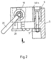
- each glue segment 1, 2 has a convexly curved glue receiving surface 4, 5, the base body 6, 7 of which is adjustably mounted on a support 8, 9 in a manner known per se.
- the carrier 8, 9 has an axial bore 10, 11 in the center of curvature of the convexly curved receiving surface 4, 5. Between this axial bore 10, 11 and the glue-receiving surface 4, 5, a further axial bore is provided as a plug-in receptacle 12, 13 for the drive shaft 3.
- the wall of the carrier 8, 9 between the axial bore 10, 11 and the plug-in receptacle 12, 13 has a continuous axial slot 14, 15. Runs straight through the wall a bore 16, 17, which partially passes through the axial bore 10, 11 and through which a clamping bolt 18, 19 for clamping the carrier 8, 9 runs on the drive shaft 3.
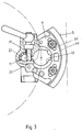
- Each clamping bolt 18, 19 has a toggle 20, as shown in FIGS. 2 and 3.
- each axial bore 10, 11 there is a bushing 21, 22, which has axially offset recesses 23, 24, 25, 26 for the clamping bolt 18, 19. In this way, the bushing 21, 22 can be axially secured, regardless of the end from which it is inserted into the axial bore 10, 11.
- the bushing 21, 22 carries a collar 27, 28, which can be of different heights depending on the desired position of the glue segment 1, 2 on the drive shaft 3. While the collar 27 is supported on the edge 29 of the axial bore 10, the collar 28 is supported on an end face 30 of the base body 7 of the receiving surface 5.
- the glue segment 1 is held at a certain distance from the glue segment 2 in that the collar 27 is supported on the upper edge 31 of the base body 9 of the lower glue segment 2.
- the collar 28 of the lower bush 22, however, is supported on a ring 32 of the shaft 3 serving as an abutment.
- each collar 27 has a projection 33 on one side, which has a concave recess 34 on the shaft side. As a result, a larger support surface is obtained on the ring 32 and the collar 27 is also secured against rotation.
- the collar 27, 28, which is formed on the bushing 21, 22 and acts as a spacer element, has a great height from the production point of view and is shortened to the size suitable for positioning the glue segments 1, 2.
- a spring groove guide 36 is arranged in addition to the anti-rotation device designed as a spring groove connection 35, which has a groove 36 a in the plug receptacle 12, 13 of each glue segment 1, 2 and one Pin 36b in the drive shaft.
Landscapes
- Lining And Supports For Tunnels (AREA)
- Labeling Devices (AREA)
- Dental Tools And Instruments Or Auxiliary Dental Instruments (AREA)
Applications Claiming Priority (2)
| Application Number | Priority Date | Filing Date | Title |
|---|---|---|---|
| DE3837362 | 1988-11-03 | ||
| DE3837362A DE3837362C1 (xx) | 1988-11-03 | 1988-11-03 |
Publications (2)
| Publication Number | Publication Date |
|---|---|
| EP0368010A1 EP0368010A1 (de) | 1990-05-16 |
| EP0368010B1 true EP0368010B1 (de) | 1992-03-04 |
Family
ID=6366431
Family Applications (1)
| Application Number | Title | Priority Date | Filing Date |
|---|---|---|---|
| EP89118862A Expired - Lifetime EP0368010B1 (de) | 1988-11-03 | 1989-10-11 | Auf eine Antriebswelle aufsteckbares festklemmbares Leimsegment |
Country Status (5)
| Country | Link |
|---|---|
| US (1) | US5062918A (xx) |
| EP (1) | EP0368010B1 (xx) |
| CA (1) | CA2002232A1 (xx) |
| DE (2) | DE3837362C1 (xx) |
| ES (1) | ES2030572T3 (xx) |
Families Citing this family (13)
| Publication number | Priority date | Publication date | Assignee | Title |
|---|---|---|---|---|
| US7814647B2 (en) | 2005-05-27 | 2010-10-19 | Prairie Packaging, Inc. | Reinforced plastic foam cup, method of and apparatus for manufacturing same |
| US7818866B2 (en) | 2005-05-27 | 2010-10-26 | Prairie Packaging, Inc. | Method of reinforcing a plastic foam cup |
| US7694843B2 (en) | 2005-05-27 | 2010-04-13 | Prairie Packaging, Inc. | Reinforced plastic foam cup, method of and apparatus for manufacturing same |
| US7704347B2 (en) | 2005-05-27 | 2010-04-27 | Prairie Packaging, Inc. | Reinforced plastic foam cup, method of and apparatus for manufacturing same |
| US8828170B2 (en) | 2010-03-04 | 2014-09-09 | Pactiv LLC | Apparatus and method for manufacturing reinforced containers |
| US9905953B1 (en) | 2016-09-30 | 2018-02-27 | Slobodan Pavlovic | High power spring-actuated electrical connector |
| CN111937250B (zh) | 2018-02-26 | 2022-09-30 | 皇家精密制品有限责任公司 | 用于高功率应用的弹簧致动式电连接器 |
| CN112956085B (zh) | 2018-06-07 | 2023-09-15 | 皇家精密制品有限责任公司 | 具有内部弹簧部件的电连接器系统及其应用 |
| WO2020154330A1 (en) | 2019-01-21 | 2020-07-30 | Royal Precision Products, Llc | Power distribution assembly with boltless busbar system |
| JP2022547535A (ja) | 2019-09-09 | 2022-11-14 | ロイヤル プリシジョン プロダクツ エルエルシー | 読み取り可能かつ記録可能な印を有するコネクタ記録システム |
| US11721942B2 (en) | 2019-09-09 | 2023-08-08 | Eaton Intelligent Power Limited | Connector system for a component in a power management system in a motor vehicle |
| JP2023537688A (ja) | 2020-07-29 | 2023-09-05 | イートン インテリジェント パワー リミテッド | インターロックシステムを含むコネクタシステム |
| DE202020104801U1 (de) | 2020-08-19 | 2021-11-25 | Krones Ag | Schnellwechselsysteme für Etikettieraggregat |
Family Cites Families (9)
| Publication number | Priority date | Publication date | Assignee | Title |
|---|---|---|---|---|
| GB932406A (en) * | 1961-04-29 | 1963-07-24 | Morgan Fairest Ltd | Improvements in or relating to labelling machines |
| DE2263947C3 (de) * | 1972-12-29 | 1982-06-24 | Jagenberg-Werke AG, 4000 Düsseldorf | Etikettiermaschine zum Aufbringen beleimter Etiketten auf stetig vorbewegte Flaschen oder andere Gegenstände |
| US4092207A (en) * | 1974-07-14 | 1978-05-30 | Jagenberg-Werke Aktiengesellschaft | Bottle labeling machine |
| DE2435582C3 (de) * | 1974-07-24 | 1978-11-16 | Jagenberg-Werke Ag, 4000 Duesseldorf | Entnahmeelement für Etiketten in einer Etikettiermaschine |
| DE2517442C3 (de) * | 1975-04-19 | 1984-09-06 | Jagenberg-Werke AG, 4000 Düsseldorf | Etikettiermaschine |
| DE3013082A1 (de) * | 1980-04-03 | 1981-10-08 | Jagenberg-Werke AG, 4000 Düsseldorf | Etikettierstation einer etikettiermaschine, insbesondere flaschen |
| DE3050382C1 (de) * | 1980-06-27 | 1984-10-31 | Jagenberg-Werke AG, 4000 Düsseldorf | Etikettiermaschine fuer Gegenstaende,insbesondere Flaschen |
| DE3044879C2 (de) * | 1980-11-28 | 1982-12-30 | Hermann 8404 Wörth Kronseder | Etikettiervorrichtung für Flaschen o.dgl. |
| DE3216138C2 (de) * | 1982-04-30 | 1984-06-14 | Hermann 8404 Wörth Kronseder | Etikettiervorrichtung für Flaschen o. dgl. |
-
1988
- 1988-11-03 DE DE3837362A patent/DE3837362C1/de not_active Expired - Fee Related
-
1989
- 1989-10-11 EP EP89118862A patent/EP0368010B1/de not_active Expired - Lifetime
- 1989-10-11 ES ES198989118862T patent/ES2030572T3/es not_active Expired - Lifetime
- 1989-10-11 DE DE8989118862T patent/DE58900924D1/de not_active Expired - Fee Related
- 1989-11-03 CA CA002002232A patent/CA2002232A1/en not_active Abandoned
- 1989-11-03 US US07/432,113 patent/US5062918A/en not_active Expired - Fee Related
Also Published As
| Publication number | Publication date |
|---|---|
| EP0368010A1 (de) | 1990-05-16 |
| CA2002232A1 (en) | 1990-05-03 |
| ES2030572T3 (es) | 1992-11-01 |
| US5062918A (en) | 1991-11-05 |
| DE3837362C1 (xx) | 1990-06-21 |
| DE58900924D1 (de) | 1992-04-09 |
Similar Documents
| Publication | Publication Date | Title |
|---|---|---|
| EP0368010B1 (de) | Auf eine Antriebswelle aufsteckbares festklemmbares Leimsegment | |
| EP0610726A1 (de) | Haltevorrichtung | |
| DE1300470B (de) | Verstellbare Halterungsvorrichtung | |
| AT395911B (de) | Anreisslehre fuer die scharniermontage | |
| DE3614121A1 (de) | Pressvorrichtung mit auswechselbaren werkzeugteilen | |
| DE1893600U (de) | Vorrichtung zur halterung von ferritkernen. | |
| DE3031283C2 (de) | Druckkopf und Verfahren zu dessen Herstellung | |
| DE2944666C2 (de) | Vorrichtung zum Ablängen und Biegen der Anschlußdrähte von elektrischen Bauelementen | |
| DE3144547C2 (xx) | ||
| DE2634376C3 (de) | Widerstandstraeger fuer einen lastumschalter einer lastregelanlage eines elektrischen transformators | |
| DE1410317A1 (de) | Maschinenstricknadel | |
| DE4010335C2 (xx) | ||
| EP0086995A1 (de) | Grundkörper insbesondere für Skibindungen | |
| DE8210282U1 (de) | Haltevorrichtung fuer gasduese, thermoelement und zuendelektrode eines zuendbrenners | |
| EP0203369B1 (de) | Anordnung für oder in Dreheisen- bzw. Drehspulinstrumenten | |
| DE2144693C3 (de) | Abnehmbarer Typenkopf für eine Druckvorrichtung | |
| DE2034993B2 (de) | Schneidwerkzeug für spanabhebende Bearbeitung | |
| DE3417410A1 (de) | Elektromagnetische abschirmvorrichtung | |
| DE2729132C3 (xx) | ||
| DE2463105C2 (de) | Vorrichtung zum Ablängen und Biegen der Anschlußdrähte elektrischer Bauelemente | |
| EP0539798B1 (de) | Gerätefuss für Fernsprechgeräte | |
| DE2537036C3 (de) | Lenkstockschalter mit einem hohlzylindrischen Teil zwischen Lenkrohr und Lenksäule | |
| DE2841866C2 (de) | Folgeschnittwerkzeug für Stanzmaschinen | |
| DE2261775A1 (de) | Reibungskupplung | |
| DE2359059C3 (de) | Schneidwerkzeug für die spanabhebende Bearbeitung |
Legal Events
| Date | Code | Title | Description |
|---|---|---|---|
| PUAI | Public reference made under article 153(3) epc to a published international application that has entered the european phase |
Free format text: ORIGINAL CODE: 0009012 |
|
| AK | Designated contracting states |
Kind code of ref document: A1 Designated state(s): DE ES FR GB IT |
|
| 17P | Request for examination filed |
Effective date: 19900716 |
|
| 17Q | First examination report despatched |
Effective date: 19910812 |
|
| ITF | It: translation for a ep patent filed |
Owner name: DE DOMINICIS & MAYER S.R.L. |
|
| GRAA | (expected) grant |
Free format text: ORIGINAL CODE: 0009210 |
|
| AK | Designated contracting states |
Kind code of ref document: B1 Designated state(s): DE ES FR GB IT |
|
| REF | Corresponds to: |
Ref document number: 58900924 Country of ref document: DE Date of ref document: 19920409 |
|
| ET | Fr: translation filed | ||
| GBT | Gb: translation of ep patent filed (gb section 77(6)(a)/1977) | ||
| REG | Reference to a national code |
Ref country code: ES Ref legal event code: FG2A Ref document number: 2030572 Country of ref document: ES Kind code of ref document: T3 |
|
| PLBE | No opposition filed within time limit |
Free format text: ORIGINAL CODE: 0009261 |
|
| STAA | Information on the status of an ep patent application or granted ep patent |
Free format text: STATUS: NO OPPOSITION FILED WITHIN TIME LIMIT |
|
| 26N | No opposition filed | ||
| PGFP | Annual fee paid to national office [announced via postgrant information from national office to epo] |
Ref country code: GB Payment date: 19950809 Year of fee payment: 7 |
|
| PGFP | Annual fee paid to national office [announced via postgrant information from national office to epo] |
Ref country code: ES Payment date: 19950817 Year of fee payment: 7 |
|
| PG25 | Lapsed in a contracting state [announced via postgrant information from national office to epo] |
Ref country code: GB Effective date: 19961011 |
|
| PG25 | Lapsed in a contracting state [announced via postgrant information from national office to epo] |
Ref country code: ES Free format text: LAPSE BECAUSE OF THE APPLICANT RENOUNCES Effective date: 19961014 |
|
| GBPC | Gb: european patent ceased through non-payment of renewal fee |
Effective date: 19961011 |
|
| PGFP | Annual fee paid to national office [announced via postgrant information from national office to epo] |
Ref country code: FR Payment date: 19970814 Year of fee payment: 9 |
|
| PG25 | Lapsed in a contracting state [announced via postgrant information from national office to epo] |
Ref country code: FR Free format text: LAPSE BECAUSE OF NON-PAYMENT OF DUE FEES Effective date: 19990630 |
|
| REG | Reference to a national code |
Ref country code: FR Ref legal event code: ST |
|
| REG | Reference to a national code |
Ref country code: ES Ref legal event code: FD2A Effective date: 20010402 |
|
| PGFP | Annual fee paid to national office [announced via postgrant information from national office to epo] |
Ref country code: DE Payment date: 20040702 Year of fee payment: 16 |
|
| PG25 | Lapsed in a contracting state [announced via postgrant information from national office to epo] |
Ref country code: IT Free format text: LAPSE BECAUSE OF NON-PAYMENT OF DUE FEES;WARNING: LAPSES OF ITALIAN PATENTS WITH EFFECTIVE DATE BEFORE 2007 MAY HAVE OCCURRED AT ANY TIME BEFORE 2007. THE CORRECT EFFECTIVE DATE MAY BE DIFFERENT FROM THE ONE RECORDED. Effective date: 20051011 |
|
| PG25 | Lapsed in a contracting state [announced via postgrant information from national office to epo] |
Ref country code: DE Free format text: LAPSE BECAUSE OF NON-PAYMENT OF DUE FEES Effective date: 20060503 |