EP0360221B1 - Procédé et dispositif pour réaliser un ancrage scellé dans un terrain adjacent à une paroi, en particulier en palplanches, immergée - Google Patents
Procédé et dispositif pour réaliser un ancrage scellé dans un terrain adjacent à une paroi, en particulier en palplanches, immergée Download PDFInfo
- Publication number
- EP0360221B1 EP0360221B1 EP89117305A EP89117305A EP0360221B1 EP 0360221 B1 EP0360221 B1 EP 0360221B1 EP 89117305 A EP89117305 A EP 89117305A EP 89117305 A EP89117305 A EP 89117305A EP 0360221 B1 EP0360221 B1 EP 0360221B1
- Authority
- EP
- European Patent Office
- Prior art keywords
- anchor
- borehole
- tubing
- wall
- seal
- Prior art date
- Legal status (The legal status is an assumption and is not a legal conclusion. Google has not performed a legal analysis and makes no representation as to the accuracy of the status listed.)
- Expired - Lifetime
Links
Images

Classifications
-
- E—FIXED CONSTRUCTIONS
- E02—HYDRAULIC ENGINEERING; FOUNDATIONS; SOIL SHIFTING
- E02D—FOUNDATIONS; EXCAVATIONS; EMBANKMENTS; UNDERGROUND OR UNDERWATER STRUCTURES
- E02D5/00—Bulkheads, piles, or other structural elements specially adapted to foundation engineering
- E02D5/74—Means for anchoring structural elements or bulkheads
- E02D5/76—Anchorings for bulkheads or sections thereof in as much as specially adapted therefor
Definitions
- the invention relates to a method for producing a compression anchor through a wall that closes a floor with pressurized water, in particular sheet pile wall, and a device for carrying out this method with the features of the preambles of patent claims 1 and 9.
- EP-A-0 218 987 discloses such a method and an apparatus for carrying out the method.
- a core drill pipe sealed by means of a stuffing box and sealed on the air side is used for drilling an opening in the sheet pile wall for the subsequent insertion of a drill pipe for drilling the anchor hole.
- a lock slide must be closed before pulling the core drill pipe out of the drill sluice. After inserting the drill pipe into the drilling lock, this gate valve can be opened again.
- the drill pipe is closed with a drill tip or drill bit at the earth end.
- an anchor rod with a claw device is inserted into the advancing pipe, which is driven in shots, at the end on the earth side.
- this anchor rod is sealed with a sealing plate against the inner wall of the drill pipe.
- an annular hose seal is still provided in the area of the anchor chair, which is attached to the anchor rod in a watertight manner, but is initially not activated by a pressure medium.
- the pre-drive pipe is then filled with hardening material and pulled back briefly, so that the previously tight drilling tip remains in the ground.
- the claw device of the anchor rod is stuck in the ground.
- the borehole is filled up to the activated ring hose seal with constant repressing of hardening building material via the injection line and pulling back the drill pipe. Then the gate valve with stuffing box and drill pipe be removed.
- An anchor plate can now be placed on the rest of the anchor chair and an anchor head on the anchor rod.
- the disadvantage here is that the production of the opening for the drill pipe by using a core drill pipe requires a cumbersome additional work phase with the additional use of a locking slide.
- the attachment of a ring hose seal and a sealing plate to the anchor rod requires an appropriate assignment to the corresponding parts of the anchor chair.
- the invention has for its object to improve this known method and device so that a simple creation of the anchor and a simpler design of the anchor chair used and the necessary sealing means is possible.
- the invention offers the advantage that the creation of an opening for the drill pipe in the wall that closes the floor with pressurized water, for example a sheet pile wall, is simplified.
- the seals in the anchor chair for the drill pipe and for the anchor tension member (s) are simplified. Since the ring hose seal used is not on the anchor tension member but is attached to the anchor chair, the pressure medium can be easily and safely introduced into the ring hose seal via an outwardly directed valve.
- the length of the anchor chair can also be shortened because the position of the ring hose seal can be precisely fixed.
- the anchor can be made by drilling with a dense as well as with an open drill bit on the drill pipe or a drill bit with flushing channels.
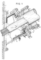
- the sheet pile wall 1 closes off a floor area 2 with a higher groundwater table.
- This sheet pile 1 is to be secured to the ground pressure by anchoring.
- the sheet pile wall 1 is provided with an only prepared opening 3 for the production of a compression anchor through the sheet pile wall 1. For this, e.g. cut the sheet piling into an elliptical shape according to the borehole to be created.
- An anchor chair 4 is attached to the sheet pile wall 1, associated with such a prepared opening 3.
- This anchor chair 4 consists of a base plate 5, which is attached to the sheet piling wall 1 by means of screws 6 on welding studs Sheet pile 1 is attached.
- Welded to the base plate 5 is a pipe socket 7 which is inclined, for example at an angle of 30 °.
- This pipe socket 7 encloses an anchor lock 8.
- a holding plate 9 is screwed onto the free socket end, for example by means of a stud bolt 10.
- the holding plate 9 has a central passage opening 11. With the underside of this holding plate 9, an initially flattened hose ring seal 14 is fastened by means of a clamping ring 12 which is fastened to the holding plate by means of screws 13.
- the hose ring seal 14 has a valve 15, the socket of which is guided through the pipe socket 7 to the outside.
- the valve 15 can be connected to a pressure source (not shown) for a pressure medium. If this pressure medium is fed to the hose ring seal 15, the hose ring seal is inflated, as indicated by the broken line.
- the hose ring seal 14 is formed by an overlapped band provided with beads 16.
- the clamping ring 12 then has a corresponding holding groove 17.
- the hose ring seal 14 either has a flat-shaped initial shape or this is forced by applying a vacuum.
- Another base plate 18 is screwed together with the holding plate 9, with which a further pipe socket 19 is welded.
- This base plate 18 also has a passage opening 20. It has a step-shaped edge 21 which covers the heads of the screws 13 while reducing the plate thickness.
- a squeezable ring seal 22 is arranged adjacent to the base plate 18 and to the inner surface of the pipe socket 19.
- a press ring 23 is arranged above the ring seal 22 and has a plurality of welded-on eyes 24. Screw bolts 25 are fastened to the outer circumference of the pipe socket 19. By tightening the nuts 26, the press ring 23 can be pressed against the ring seal 22.
- a conventional drill pipe 30 is first inserted into the anchor stool 4 fastened to the sheet pile wall 1.
- This drill pipe which is sealed at the end by a drill bit, is sunk with a conventional ram boring device.
- the pinch seal 22 is suitably pressed against the outer wall of the drill pipe 30.
- an anchor pulling member 31 is inserted into the drill pipe which is open at the rear end.
- the anchor tension member 31 can consist of one or more anchor rods or strands. The anchor tension member is inserted up to the bottom end of the drill pipe 30.
- this can be filled with hardening building material.
- the drill pipe 30 is then closed on the air side with a compression cap.
- the drill pipe 30 is withdrawn a short distance and then e.g. the drill bit can be detached by applying a high compression pressure to the building material in the drill pipe 30 by means of a piece of hose passed through the compression cap.
- the drill bit can also be cut off by means of an inserted anchor tension member.
- the anchor tension member is fixed in its position by the building material having a stiffer consistency.
- the anchor tension member 31 has one or more post-injection channels, not shown, in the axial direction of the anchor tension member 31.
- the channels have radial openings over the pressing section of the anchor for the free exit of the injected, hardening building material which is injected after the primary building material has hardened.
- a closed line must be provided over the free length of the anchor tension member.
- a compression line fixed to the anchor can be provided for the primary building material.
- the further injection of hardening building material takes place, as usual, by pulling back the drill pipe 30.
- the hardening building material is then injected under pressure into the region of the drawn drill pipe 30 between the anchor pulling member 31 and the wall of the borehole 30, under pressure.
- the annular hose seal 14 is now inflated by the pressure medium, which is supplied under pressure via the valve 15, as indicated by the broken line. It presses against the outer surface of the anchor tension member 31 or against the surrounding cladding tube and, if necessary, on external lines for supplying the hardening building material. By expanding the ring hose seal 14, the building material present in the anchor lock 4 is partially displaced.
- An immediately hardenable, rubber-like material can also be used as the printing medium. This emerges from a print cartridge placed on the valve 15 of the armature lock 4.
- a concrete wall can also be used. In this, the hole for the drill pipe is worked out while leaving a pierceable wall part.
- drilling can also be done with an open rotary drill bit or with a full drill bit with irrigation channels or using the overlay drilling method.
- the drill pipe is then closed on the air side and pressurized air is applied before the installation of a new pipe section, the anchor installation and the injection of the liquid building material. This pushes the water away from the mouth of the borehole, far into the subsoil. The time until the water flows back is sufficient to carry out the aforementioned work steps. Filling the annular space between the drill pipe and anchor and injecting it into the subsoil when the drill pipe is withdrawn in sections is done in one operation.
- the drill pipe 30 can be pulled out of the drill pipe lock 32.
- a re-grouting can take place after the injected building material has hardened before the anchor head is put on by the post-injection line mentioned.
- the change relates essentially to the anchor chair 4.
- the hose ring seal 14 should be housed protected until it is intended to serve its sealing purposes.
- the pipe socket 7 of the armature chair 4 is sealed by a single base plate 18 via an annular seal 42.
- a pipe socket 40 is firmly connected to the base plate 18.
- the edges of the hose ring seal 14 are fixed by clamping rings 12 fastened to the pipe socket 7 and by counter-clamping rings 41.
- clamping rings 12 fastened to the pipe socket 7 and by counter-clamping rings 41.
Claims (12)
- Procédé de fabrication d'un ancrage scellé traversant une paroi adjacente à un terrain imprégné d'eau sous pression, notamment une paroi (1) en palplanches, dans lequel une chaise (4) d'ancrage est installée sur la paroi, la chaise comportant un sas tubulaire comprenant un joint (22) d'étanchéité, prévu pour le tube de sondage (30), et un sas (8) d'ancrage comprenant un joint tubulaire annulaire (14) d'étanchéité, prévu pour au moins un tirant d'ancrage (31), et dans lequel une matière de construction durcissable peut être injectée, par l'intermédiaire d'un canal d'injection et, le cas échéant, par l'intermédiaire d'un canal d'injection secondaire, dans la chambre annulaire comprise entre le tubage de forage et le tirant, voire la paroi du trou de forage, l'injection étant accompagnée d'un retrait du tube de sondage, caractérisé en ce que le canal d'injection secondaire et, le cas échéant, le canal d'injection sont disposés à l'intérieur de la circonférence du tirant (31), ou en appui sur celui-ci, et en ce que le joint tubulaire annulaire (14) d'étanchéité est prévu de façon fixe dans l'espace, dans le sas (8) d'ancrage, le joint tubulaire annulaire (14) d'étanchéité pouvant être gonflé par l'intermédiaire d'une valve (15) débouchant à l'extérieur.
- Procédé selon la revendication 1, caractérisé en ce que la découpe (3) pour le tube de sondage (30), ménagée dans la paroi (1) de fermeture, est en partie préformée et est finie par détachage au moyen du tube de sondage (30) inséré et étanché.
- Procédé selon la revendication 1, caractérisé en ce qu'après le retrait du tube de sondage (30) étanché, accompagné d'une injection simultanée de matière de construction durcissable, jusqu'à l'arrière du joint tubulaire annulaire (14) d'étanchéité, ce dernier est gonflé au moyen d'un fluide sous pression et est forcé contre le tirant (31) de façon étanche.
- Procédé selon la revendication 3, caractérisé en ce qu'on injecte dans le joint tubulaire annulaire (14) d'étanchéité, afin de le gonfler, une masse caoutchouteuse durcissant instantanément, en l'injectant, le cas échéant, de façon ajustée à partir de cartouches sous pression.
- Procédé selon la revendication 1, caractérisé en ce qu'après avoir atteint sa position finale dans le sol, le tube de sondage est obturé, côté atmosphère, au moyen d'un capuchon d'injection, et en ce qu'après avoir rempli l'espace annulaire compris entre le tube de sondage et le tirant, voire l'espace intérieur du tube de sondage, par l'intermédiaire de la conduite d'injection, avant l'introduction du tirant, on injecte de la matière de construction durcissable dans le sol, par l'intermédiaire de l'entrée ménagée dans le capuchon d'injection, en retirant simultanément le tube de sondage.
- Procédé selon la revendication 1, caractérisé en ce que l'on travaille avec un tube de sondage ayant une couronne de forage étanche.
- Procédé selon la revendication 1, caractérisé en ce que l'on travaille avec un tube de sondage ayant une couronne de forage dotée de canalisations de lavage ou avec une couronne de forage ouverte annulaire, ou encore en mettant en oeuvre le procédé de forage mixte à lavage intérieur.
- Procédé selon la revendication 7, caractérisé en ce qu'avant chaque adjonction de nouvelles sections de tubage, avant l'introduction du tirant et l'injection de matière de construction fluide dans le tube de sondage, on introduit de l'air comprimé dans le tube de sondage, afin de refouler l'eau sous pression.
- Dispositif de fabrication d'un ancrage scellé à travers une paroi adjacente à un terrain imprégné d'eau sous pression, notamment une paroi (1) en palplanches, selon l'une ou plusieurs des revendications 1 à 8, comprenant une chaise (4) d'ancrage disposée sur la paroi, la chaise comprenant un sas tubulaire comprenant un joint (22) d'étanchéité, prévu pour le tube (30) de sondage, et un sas (8) d'ancrage comprenant un joint tubulaire annulaire (14) d'étanchéité, prévu pour au moins un tirant (31), et comprenant un canal d'injection et, le cas échéant, un canal d'injection secondaire, prévus pour une matière de construction durcissable injectée dans l'espace annulaire compris entre le tube (30) de sondage et le tirant, voire la paroi du trou de forage, l'injection étant accompagnée d'un retrait du tube de sondage, caractérisé en ce que le canal d'injection et/ou le canal d'injection secondaire sont disposés à l'intérieur du pourtour extérieur du tirant (31), voire du faisceau d'éléments tirants, ou à l'intérieur du tube enveloppant, et en ce que le joint tubulaire annulaire (14) d'étanchéité est installé de façon fixe dans le sas (8) d'ancrage, et en ce qu'il peut être relié à une source de pression par l'intermédiaire d'une valve (15) débouchant à l'extérieur.
- Dispositif selon la revendication 9, caractérisé en ce que le canal d'injection est constitué par une conduite ou par des éléments entretoises présentant des passages axiaux et radiaux.
- Dispositif selon la revendication 9, caractérisé en ce que le joint tubulaire annulaire présente une forme ventrue et en ce qu'il peut être raccordé à une source de dépression afin d'être aplati.
- Dispositif selon la revendication 9, caractérisé en ce que le joint tubulaire annulaire (14) d'étanchéité est protégé par une tubulure (40) l'isolant du tube (30) de sondage, en ce que cette tubulure est reliée de façon fixe à la plaque d'embase (18) fermant de façon étanche la chaise (4) d'ancrage, au moyen d'un joint presse-étoupe (22), et en ce que cette tubulure est montée de façon coulissante par rapport au bord supérieur du joint tubulaire annulaire d'étanchéité, et étanche par rapport à celui-ci, grâce à un joint torique (43).
Priority Applications (1)
| Application Number | Priority Date | Filing Date | Title |
|---|---|---|---|
| AT89117305T ATE90407T1 (de) | 1988-09-20 | 1989-09-19 | Verfahren und vorrichtung zur herstellung eines verpressankers durch eine einen boden mit druckwasser abschliessende wand, insbesondere spundwand. |
Applications Claiming Priority (2)
| Application Number | Priority Date | Filing Date | Title |
|---|---|---|---|
| DE3831926A DE3831926A1 (de) | 1988-09-20 | 1988-09-20 | Verfahren und vorrichtung zum herstellen eines verpressankers durch eine einen boden mit druckwasser abschliessende wand, insbesondere spundwand |
| DE3831926 | 1988-09-20 |
Publications (3)
| Publication Number | Publication Date |
|---|---|
| EP0360221A2 EP0360221A2 (fr) | 1990-03-28 |
| EP0360221A3 EP0360221A3 (en) | 1990-10-31 |
| EP0360221B1 true EP0360221B1 (fr) | 1993-06-09 |
Family
ID=6363333
Family Applications (1)
| Application Number | Title | Priority Date | Filing Date |
|---|---|---|---|
| EP89117305A Expired - Lifetime EP0360221B1 (fr) | 1988-09-20 | 1989-09-19 | Procédé et dispositif pour réaliser un ancrage scellé dans un terrain adjacent à une paroi, en particulier en palplanches, immergée |
Country Status (4)
| Country | Link |
|---|---|
| EP (1) | EP0360221B1 (fr) |
| AT (1) | ATE90407T1 (fr) |
| DE (2) | DE3831926A1 (fr) |
| ES (1) | ES2045321T3 (fr) |
Families Citing this family (10)
| Publication number | Priority date | Publication date | Assignee | Title |
|---|---|---|---|---|
| DE4226655C2 (de) * | 1992-08-12 | 1996-12-05 | Zueblin Ag | Verfahren zur Sicherung von Baugrubenwänden durch Setzen von spannbaren Erdankern |
| DE4305923C2 (de) * | 1993-02-26 | 1997-02-27 | Bilfinger Berger Bau | Abdichtvorrichtung für Ankerköpfe gegen drückendes Wasser |
| DE4316097A1 (de) * | 1993-05-13 | 1994-11-17 | Bauer Spezialtiefbau | Verfahren und Vorrichtung zum Setzen eines Injektionsankers |
| DE9409363U1 (de) * | 1994-06-09 | 1994-08-04 | Bilfinger Berger Bau | Abgedichtete Ankerdurchführung für Verbauwände |
| DE9416718U1 (de) * | 1994-10-18 | 1994-12-15 | Bilfinger Berger Bau | Versenkte, abgedichtete Ankerdurchführung, insbesondere für Schlitzwände |
| NL1011701C2 (nl) * | 1999-03-30 | 2000-12-04 | Van Leeuwen Harmelen Bv Geb | Werkwijze voor het verankeren van een in de grond geplaatste wand met behulp van op trek belastbare schroefankers. |
| DE10032692A1 (de) * | 2000-07-05 | 2002-01-17 | Zueblin Ag | Verfahren zur Verankerung von Baugrubenwänden bei gleichzeitiger Verminderung des Wasserdrucks auf diese Wände und Konstruktion zur Durchführung des Verfahrens |
| DE102007030697B4 (de) * | 2007-06-30 | 2014-04-03 | Stump Spezialtiefbau Gmbh | Verfahren und Anordnung zur Abdichtung einer Öffnung in Form eines Loches in einer Spundwand |
| DE102007043621B4 (de) * | 2007-09-13 | 2013-03-28 | Stump Spezialtiefbau Gmbh | Bohrungsabdichtung |
| NL2022393B1 (nl) * | 2019-01-14 | 2020-08-14 | Key Staal B V | Samenstel van een keerwand, tenminste twee langwerpige verankeringselementen en een gordingbalk |
Family Cites Families (4)
| Publication number | Priority date | Publication date | Assignee | Title |
|---|---|---|---|---|
| US3665717A (en) * | 1971-01-14 | 1972-05-30 | Soil Sampling Service Inc | Method and apparatus for installing elongated rods in unstable earth formations |
| FR2141436B1 (fr) * | 1971-06-02 | 1973-06-29 | Sif Entreprise Bachy | |
| BE887709A (fr) * | 1981-02-27 | 1981-06-15 | Camar P V B A | Werkwijze en machine voor het aanbrengen van een element doorheen een muur onder de bescherming van een sas |
| DE3535320A1 (de) * | 1985-10-03 | 1987-04-09 | Dyckerhoff & Widmann Ag | Verfahren und vorrichtung zum setzen eines stab-, draht- oder rohrfoermigen einbauteils in eine bodenformation mit drueckendem wasser |
-
1988
- 1988-09-20 DE DE3831926A patent/DE3831926A1/de not_active Withdrawn
-
1989
- 1989-09-19 EP EP89117305A patent/EP0360221B1/fr not_active Expired - Lifetime
- 1989-09-19 DE DE8989117305T patent/DE58904617D1/de not_active Expired - Fee Related
- 1989-09-19 ES ES89117305T patent/ES2045321T3/es not_active Expired - Lifetime
- 1989-09-19 AT AT89117305T patent/ATE90407T1/de not_active IP Right Cessation
Also Published As
| Publication number | Publication date |
|---|---|
| EP0360221A2 (fr) | 1990-03-28 |
| EP0360221A3 (en) | 1990-10-31 |
| DE58904617D1 (de) | 1993-07-15 |
| ES2045321T3 (es) | 1994-01-16 |
| DE3831926A1 (de) | 1990-03-22 |
| ATE90407T1 (de) | 1993-06-15 |
Similar Documents
| Publication | Publication Date | Title |
|---|---|---|
| DE3323332C2 (fr) | ||
| DE2935126A1 (de) | Verfahren zum injizieren von moertelschlamm in den erdboden | |
| DE1533576B1 (de) | Einrichtung zum Einzementieren eines Futterrohrstranges in einem Bohrloch | |
| EP0360221B1 (fr) | Procédé et dispositif pour réaliser un ancrage scellé dans un terrain adjacent à une paroi, en particulier en palplanches, immergée | |
| DE102008005452B4 (de) | Verfahren zum Verfestigen von Bodenabschnitten und Vorrichtung zur Durchführung des Verfahrens | |
| DE3840158C2 (fr) | ||
| DE3430789C2 (fr) | ||
| EP0218987A2 (fr) | Méthode pour la mise en place d'un élément de construction au travers d'un rideau de palplanches dans une formation du sol comportant de l'eau sous pression ainsi qu'un dispositif pour la mise en oeuvre de la méthode | |
| EP0421072A1 (fr) | Dispositif pour l'injection d'une résine synthétique dans des fissures dans le béton | |
| DE102005022585A1 (de) | Bohrvorsatz, insbesondere für eine Belüftungslanze, und Belüftungslanze | |
| DE4005032C2 (de) | Vorrichtung zum Aufbringen einer Kraft zwischen einer Bodenplatte und einem Gründungselement | |
| DE3626988C2 (fr) | ||
| DE4305923C2 (de) | Abdichtvorrichtung für Ankerköpfe gegen drückendes Wasser | |
| DE2505668A1 (de) | Vorrichtung an bohrausruestungen | |
| DE2651149C3 (de) | Abdichtverfahren beim Herstellen von Tunneltoren mittels Schildvortriebsvorrichtungen und Vorrichtung zur Durchführung des Verfahrens | |
| DE3100733A1 (de) | Verfahren zur befestigung von gegenstaenden an fertigen beton- oder steinwaenden sowie vorrichtung zur durchfuehrung des verfahrens | |
| DE2800370A1 (de) | Verfahren und vorrichtung zum einbauen eines verpressankers in eine bodenformation gegen drueckendes wasser | |
| EP0410304B1 (fr) | Dispositif pour l'injection de suspension | |
| DE2715967C2 (de) | Vorrichtung zum wasserdichten Durchführen eines VerpreBankers durch eine wasserrückhaltende Baugrubenwand, insbesondere Schlitzwand aus Stahlbeton | |
| DE3610118C2 (fr) | ||
| DE2829416A1 (de) | Vorrichtung und verfahren zur zementierung von pfeilern fuer bohrinseln | |
| DE4202926A1 (de) | Blaehpacker mit schutzmantel | |
| DE2515652C2 (de) | Verfahren und vorrichtung zum abdichten von traenkbohrloechern durch zementieren | |
| DE2617758B2 (de) | Verfahren zum Injizieren von Kunststoff-Füllungen in Wände, Mauern, Fassadenwände u.dgl. sowie Injektionsröhrchen zur Durchführung des Verfahrens | |
| DE2410212A1 (de) | Verschlussvorrichtung fuer kunststoffinjektionen in bohrloecher beim sicherungsverbau sowie unter und ueber tag und verfahren zur herstellung eines verbundverbaus als gebirgssicherung im unter- und uebertagebau |
Legal Events
| Date | Code | Title | Description |
|---|---|---|---|
| PUAI | Public reference made under article 153(3) epc to a published international application that has entered the european phase |
Free format text: ORIGINAL CODE: 0009012 |
|
| AK | Designated contracting states |
Kind code of ref document: A2 Designated state(s): AT BE CH DE ES FR GB IT LI LU NL |
|
| PUAL | Search report despatched |
Free format text: ORIGINAL CODE: 0009013 |
|
| AK | Designated contracting states |
Kind code of ref document: A3 Designated state(s): AT BE CH DE ES FR GB IT LI LU NL |
|
| 17P | Request for examination filed |
Effective date: 19901207 |
|
| 17Q | First examination report despatched |
Effective date: 19920123 |
|
| RAP3 | Party data changed (applicant data changed or rights of an application transferred) |
Owner name: TGB TECHNOGRUNDBAU GMBH |
|
| GRAA | (expected) grant |
Free format text: ORIGINAL CODE: 0009210 |
|
| AK | Designated contracting states |
Kind code of ref document: B1 Designated state(s): AT BE CH DE ES FR GB IT LI LU NL |
|
| REF | Corresponds to: |
Ref document number: 90407 Country of ref document: AT Date of ref document: 19930615 Kind code of ref document: T |
|
| ITF | It: translation for a ep patent filed |
Owner name: STUDIO INGG. FISCHETTI & WEBER |
|
| REF | Corresponds to: |
Ref document number: 58904617 Country of ref document: DE Date of ref document: 19930715 |
|
| ET | Fr: translation filed | ||
| PGFP | Annual fee paid to national office [announced via postgrant information from national office to epo] |
Ref country code: CH Payment date: 19930824 Year of fee payment: 5 |
|
| GBT | Gb: translation of ep patent filed (gb section 77(6)(a)/1977) |
Effective date: 19930722 |
|
| PGFP | Annual fee paid to national office [announced via postgrant information from national office to epo] |
Ref country code: AT Payment date: 19930826 Year of fee payment: 5 |
|
| PGFP | Annual fee paid to national office [announced via postgrant information from national office to epo] |
Ref country code: BE Payment date: 19930902 Year of fee payment: 5 |
|
| PGFP | Annual fee paid to national office [announced via postgrant information from national office to epo] |
Ref country code: GB Payment date: 19930909 Year of fee payment: 5 |
|
| PGFP | Annual fee paid to national office [announced via postgrant information from national office to epo] |
Ref country code: LU Payment date: 19930915 Year of fee payment: 5 |
|
| PGFP | Annual fee paid to national office [announced via postgrant information from national office to epo] |
Ref country code: FR Payment date: 19930921 Year of fee payment: 5 |
|
| PGFP | Annual fee paid to national office [announced via postgrant information from national office to epo] |
Ref country code: NL Payment date: 19930930 Year of fee payment: 5 |
|
| EPTA | Lu: last paid annual fee | ||
| REG | Reference to a national code |
Ref country code: ES Ref legal event code: FG2A Ref document number: 2045321 Country of ref document: ES Kind code of ref document: T3 |
|
| PLBE | No opposition filed within time limit |
Free format text: ORIGINAL CODE: 0009261 |
|
| STAA | Information on the status of an ep patent application or granted ep patent |
Free format text: STATUS: NO OPPOSITION FILED WITHIN TIME LIMIT |
|
| 26N | No opposition filed | ||
| PGFP | Annual fee paid to national office [announced via postgrant information from national office to epo] |
Ref country code: ES Payment date: 19940712 Year of fee payment: 6 |
|
| PG25 | Lapsed in a contracting state [announced via postgrant information from national office to epo] |
Ref country code: LU Free format text: LAPSE BECAUSE OF NON-PAYMENT OF DUE FEES Effective date: 19940919 Ref country code: GB Effective date: 19940919 Ref country code: AT Effective date: 19940919 |
|
| PG25 | Lapsed in a contracting state [announced via postgrant information from national office to epo] |
Ref country code: LI Effective date: 19940930 Ref country code: CH Effective date: 19940930 Ref country code: BE Effective date: 19940930 |
|
| BERE | Be: lapsed |
Owner name: TECHNOGRUNDBAU G.M.B.H. TGB Effective date: 19940930 |
|
| PG25 | Lapsed in a contracting state [announced via postgrant information from national office to epo] |
Ref country code: NL Effective date: 19950401 |
|
| NLV4 | Nl: lapsed or anulled due to non-payment of the annual fee | ||
| GBPC | Gb: european patent ceased through non-payment of renewal fee |
Effective date: 19940919 |
|
| PG25 | Lapsed in a contracting state [announced via postgrant information from national office to epo] |
Ref country code: FR Effective date: 19950531 |
|
| REG | Reference to a national code |
Ref country code: CH Ref legal event code: PL |
|
| REG | Reference to a national code |
Ref country code: FR Ref legal event code: ST |
|
| PG25 | Lapsed in a contracting state [announced via postgrant information from national office to epo] |
Ref country code: ES Free format text: LAPSE BECAUSE OF NON-PAYMENT OF DUE FEES Effective date: 19950920 |
|
| PGFP | Annual fee paid to national office [announced via postgrant information from national office to epo] |
Ref country code: DE Payment date: 19961127 Year of fee payment: 8 |
|
| PG25 | Lapsed in a contracting state [announced via postgrant information from national office to epo] |
Ref country code: DE Free format text: LAPSE BECAUSE OF NON-PAYMENT OF DUE FEES Effective date: 19980603 |
|
| REG | Reference to a national code |
Ref country code: ES Ref legal event code: FD2A Effective date: 19961011 |
|
| PG25 | Lapsed in a contracting state [announced via postgrant information from national office to epo] |
Ref country code: IT Free format text: LAPSE BECAUSE OF NON-PAYMENT OF DUE FEES;WARNING: LAPSES OF ITALIAN PATENTS WITH EFFECTIVE DATE BEFORE 2007 MAY HAVE OCCURRED AT ANY TIME BEFORE 2007. THE CORRECT EFFECTIVE DATE MAY BE DIFFERENT FROM THE ONE RECORDED. Effective date: 20050919 |