EP0360221B1 - Method and apparatus for making a sealed anchor in a soil area bordered by an immersed wall, especially a sheet piling wall - Google Patents
Method and apparatus for making a sealed anchor in a soil area bordered by an immersed wall, especially a sheet piling wall Download PDFInfo
- Publication number
- EP0360221B1 EP0360221B1 EP89117305A EP89117305A EP0360221B1 EP 0360221 B1 EP0360221 B1 EP 0360221B1 EP 89117305 A EP89117305 A EP 89117305A EP 89117305 A EP89117305 A EP 89117305A EP 0360221 B1 EP0360221 B1 EP 0360221B1
- Authority
- EP
- European Patent Office
- Prior art keywords
- anchor
- borehole
- tubing
- wall
- seal
- Prior art date
- Legal status (The legal status is an assumption and is not a legal conclusion. Google has not performed a legal analysis and makes no representation as to the accuracy of the status listed.)
- Expired - Lifetime
Links
- 238000000034 method Methods 0.000 title claims abstract description 22
- 239000002689 soil Substances 0.000 title claims abstract 8
- 238000002347 injection Methods 0.000 claims abstract description 14
- 239000007924 injection Substances 0.000 claims abstract description 14
- 238000007789 sealing Methods 0.000 claims abstract description 8
- 239000004566 building material Substances 0.000 claims description 19
- 238000005553 drilling Methods 0.000 claims description 11
- XLYOFNOQVPJJNP-UHFFFAOYSA-N water Substances O XLYOFNOQVPJJNP-UHFFFAOYSA-N 0.000 claims description 9
- 230000006835 compression Effects 0.000 claims description 7
- 238000007906 compression Methods 0.000 claims description 7
- 238000004519 manufacturing process Methods 0.000 claims description 4
- 239000007788 liquid Substances 0.000 claims description 2
- 238000005056 compaction Methods 0.000 claims 8
- 239000012530 fluid Substances 0.000 claims 2
- 230000008595 infiltration Effects 0.000 claims 2
- 238000001764 infiltration Methods 0.000 claims 2
- 239000000463 material Substances 0.000 abstract description 3
- 210000000078 claw Anatomy 0.000 description 3
- 238000003825 pressing Methods 0.000 description 3
- 238000003780 insertion Methods 0.000 description 2
- 230000037431 insertion Effects 0.000 description 2
- 238000009434 installation Methods 0.000 description 2
- 238000004873 anchoring Methods 0.000 description 1
- 239000011324 bead Substances 0.000 description 1
- 238000005253 cladding Methods 0.000 description 1
- 238000011010 flushing procedure Methods 0.000 description 1
- 239000003673 groundwater Substances 0.000 description 1
- 230000002262 irrigation Effects 0.000 description 1
- 238000003973 irrigation Methods 0.000 description 1
- 239000002184 metal Substances 0.000 description 1
- 230000000754 repressing effect Effects 0.000 description 1
- 238000009423 ventilation Methods 0.000 description 1
- 238000013022 venting Methods 0.000 description 1
- 238000003466 welding Methods 0.000 description 1
Images

Classifications
-
- E—FIXED CONSTRUCTIONS
- E02—HYDRAULIC ENGINEERING; FOUNDATIONS; SOIL SHIFTING
- E02D—FOUNDATIONS; EXCAVATIONS; EMBANKMENTS; UNDERGROUND OR UNDERWATER STRUCTURES
- E02D5/00—Bulkheads, piles, or other structural elements specially adapted to foundation engineering
- E02D5/74—Means for anchoring structural elements or bulkheads
- E02D5/76—Anchorings for bulkheads or sections thereof in as much as specially adapted therefor
Definitions
- the invention relates to a method for producing a compression anchor through a wall that closes a floor with pressurized water, in particular sheet pile wall, and a device for carrying out this method with the features of the preambles of patent claims 1 and 9.
- EP-A-0 218 987 discloses such a method and an apparatus for carrying out the method.
- a core drill pipe sealed by means of a stuffing box and sealed on the air side is used for drilling an opening in the sheet pile wall for the subsequent insertion of a drill pipe for drilling the anchor hole.
- a lock slide must be closed before pulling the core drill pipe out of the drill sluice. After inserting the drill pipe into the drilling lock, this gate valve can be opened again.
- the drill pipe is closed with a drill tip or drill bit at the earth end.
- an anchor rod with a claw device is inserted into the advancing pipe, which is driven in shots, at the end on the earth side.
- this anchor rod is sealed with a sealing plate against the inner wall of the drill pipe.
- an annular hose seal is still provided in the area of the anchor chair, which is attached to the anchor rod in a watertight manner, but is initially not activated by a pressure medium.
- the pre-drive pipe is then filled with hardening material and pulled back briefly, so that the previously tight drilling tip remains in the ground.
- the claw device of the anchor rod is stuck in the ground.
- the borehole is filled up to the activated ring hose seal with constant repressing of hardening building material via the injection line and pulling back the drill pipe. Then the gate valve with stuffing box and drill pipe be removed.
- An anchor plate can now be placed on the rest of the anchor chair and an anchor head on the anchor rod.
- the disadvantage here is that the production of the opening for the drill pipe by using a core drill pipe requires a cumbersome additional work phase with the additional use of a locking slide.
- the attachment of a ring hose seal and a sealing plate to the anchor rod requires an appropriate assignment to the corresponding parts of the anchor chair.
- the invention has for its object to improve this known method and device so that a simple creation of the anchor and a simpler design of the anchor chair used and the necessary sealing means is possible.
- the invention offers the advantage that the creation of an opening for the drill pipe in the wall that closes the floor with pressurized water, for example a sheet pile wall, is simplified.
- the seals in the anchor chair for the drill pipe and for the anchor tension member (s) are simplified. Since the ring hose seal used is not on the anchor tension member but is attached to the anchor chair, the pressure medium can be easily and safely introduced into the ring hose seal via an outwardly directed valve.
- the length of the anchor chair can also be shortened because the position of the ring hose seal can be precisely fixed.
- the anchor can be made by drilling with a dense as well as with an open drill bit on the drill pipe or a drill bit with flushing channels.
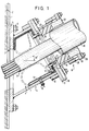
- the sheet pile wall 1 closes off a floor area 2 with a higher groundwater table.
- This sheet pile 1 is to be secured to the ground pressure by anchoring.
- the sheet pile wall 1 is provided with an only prepared opening 3 for the production of a compression anchor through the sheet pile wall 1. For this, e.g. cut the sheet piling into an elliptical shape according to the borehole to be created.
- An anchor chair 4 is attached to the sheet pile wall 1, associated with such a prepared opening 3.
- This anchor chair 4 consists of a base plate 5, which is attached to the sheet piling wall 1 by means of screws 6 on welding studs Sheet pile 1 is attached.
- Welded to the base plate 5 is a pipe socket 7 which is inclined, for example at an angle of 30 °.
- This pipe socket 7 encloses an anchor lock 8.
- a holding plate 9 is screwed onto the free socket end, for example by means of a stud bolt 10.
- the holding plate 9 has a central passage opening 11. With the underside of this holding plate 9, an initially flattened hose ring seal 14 is fastened by means of a clamping ring 12 which is fastened to the holding plate by means of screws 13.
- the hose ring seal 14 has a valve 15, the socket of which is guided through the pipe socket 7 to the outside.
- the valve 15 can be connected to a pressure source (not shown) for a pressure medium. If this pressure medium is fed to the hose ring seal 15, the hose ring seal is inflated, as indicated by the broken line.
- the hose ring seal 14 is formed by an overlapped band provided with beads 16.
- the clamping ring 12 then has a corresponding holding groove 17.
- the hose ring seal 14 either has a flat-shaped initial shape or this is forced by applying a vacuum.
- Another base plate 18 is screwed together with the holding plate 9, with which a further pipe socket 19 is welded.
- This base plate 18 also has a passage opening 20. It has a step-shaped edge 21 which covers the heads of the screws 13 while reducing the plate thickness.
- a squeezable ring seal 22 is arranged adjacent to the base plate 18 and to the inner surface of the pipe socket 19.
- a press ring 23 is arranged above the ring seal 22 and has a plurality of welded-on eyes 24. Screw bolts 25 are fastened to the outer circumference of the pipe socket 19. By tightening the nuts 26, the press ring 23 can be pressed against the ring seal 22.
- a conventional drill pipe 30 is first inserted into the anchor stool 4 fastened to the sheet pile wall 1.
- This drill pipe which is sealed at the end by a drill bit, is sunk with a conventional ram boring device.
- the pinch seal 22 is suitably pressed against the outer wall of the drill pipe 30.
- an anchor pulling member 31 is inserted into the drill pipe which is open at the rear end.
- the anchor tension member 31 can consist of one or more anchor rods or strands. The anchor tension member is inserted up to the bottom end of the drill pipe 30.
- this can be filled with hardening building material.
- the drill pipe 30 is then closed on the air side with a compression cap.
- the drill pipe 30 is withdrawn a short distance and then e.g. the drill bit can be detached by applying a high compression pressure to the building material in the drill pipe 30 by means of a piece of hose passed through the compression cap.
- the drill bit can also be cut off by means of an inserted anchor tension member.
- the anchor tension member is fixed in its position by the building material having a stiffer consistency.
- the anchor tension member 31 has one or more post-injection channels, not shown, in the axial direction of the anchor tension member 31.
- the channels have radial openings over the pressing section of the anchor for the free exit of the injected, hardening building material which is injected after the primary building material has hardened.
- a closed line must be provided over the free length of the anchor tension member.
- a compression line fixed to the anchor can be provided for the primary building material.
- the further injection of hardening building material takes place, as usual, by pulling back the drill pipe 30.
- the hardening building material is then injected under pressure into the region of the drawn drill pipe 30 between the anchor pulling member 31 and the wall of the borehole 30, under pressure.
- the annular hose seal 14 is now inflated by the pressure medium, which is supplied under pressure via the valve 15, as indicated by the broken line. It presses against the outer surface of the anchor tension member 31 or against the surrounding cladding tube and, if necessary, on external lines for supplying the hardening building material. By expanding the ring hose seal 14, the building material present in the anchor lock 4 is partially displaced.
- An immediately hardenable, rubber-like material can also be used as the printing medium. This emerges from a print cartridge placed on the valve 15 of the armature lock 4.
- a concrete wall can also be used. In this, the hole for the drill pipe is worked out while leaving a pierceable wall part.
- drilling can also be done with an open rotary drill bit or with a full drill bit with irrigation channels or using the overlay drilling method.
- the drill pipe is then closed on the air side and pressurized air is applied before the installation of a new pipe section, the anchor installation and the injection of the liquid building material. This pushes the water away from the mouth of the borehole, far into the subsoil. The time until the water flows back is sufficient to carry out the aforementioned work steps. Filling the annular space between the drill pipe and anchor and injecting it into the subsoil when the drill pipe is withdrawn in sections is done in one operation.
- the drill pipe 30 can be pulled out of the drill pipe lock 32.
- a re-grouting can take place after the injected building material has hardened before the anchor head is put on by the post-injection line mentioned.
- the change relates essentially to the anchor chair 4.
- the hose ring seal 14 should be housed protected until it is intended to serve its sealing purposes.
- the pipe socket 7 of the armature chair 4 is sealed by a single base plate 18 via an annular seal 42.
- a pipe socket 40 is firmly connected to the base plate 18.
- the edges of the hose ring seal 14 are fixed by clamping rings 12 fastened to the pipe socket 7 and by counter-clamping rings 41.
- clamping rings 12 fastened to the pipe socket 7 and by counter-clamping rings 41.
Landscapes
- Engineering & Computer Science (AREA)
- Structural Engineering (AREA)
- Life Sciences & Earth Sciences (AREA)
- General Life Sciences & Earth Sciences (AREA)
- Mining & Mineral Resources (AREA)
- Paleontology (AREA)
- Civil Engineering (AREA)
- General Engineering & Computer Science (AREA)
- Piles And Underground Anchors (AREA)
- Joining Of Building Structures In Genera (AREA)
- Cultivation Receptacles Or Flower-Pots, Or Pots For Seedlings (AREA)
- Nozzles (AREA)
Abstract
Description
Die Erfindung betrifft ein Verfahren zum Herstellen eines Verpreßankers durch eine einen Boden mit Druckwasser abschließende Wand, insbesondere Spundwand sowie eine Vorrichtung zum Ausführen dieses Verfahrens mit den Merkmalen der Oberbegriffe der Patentansprüche 1 und 9.The invention relates to a method for producing a compression anchor through a wall that closes a floor with pressurized water, in particular sheet pile wall, and a device for carrying out this method with the features of the preambles of
Aus der EP-A-0 218 987 ist ein derartiges Verfahren sowie eine Vorrichtung zur Durchführung des Verfahrens bekannt. Hierbei wird ein mittels einer Stopfbuchse abgedichtetes, luftseitig abgeschlossenes Kernbohrrohr zum Aufbohren einer Öffnung in der Spundwand für das nachträgliche Einführen eines Bohrrohres zum Bohren des Ankerloches verwendet. Vor dem Abziehen des Kernbohrrohres aus der Bohrschleuse muß ein Sperrschieber geschlossen werden. Nach dem Einführen des Bohrrohres in die Bohrschleuse kann dieser Sperrschieber wieder geöffnet werden. Das Bohrrohr ist mit einer Bohrspitze bzw. Bohrkrone am erdseitigen Ende verschlossen. In das schußweise vorgetriebene Vortreibrohr wird nach Erreichen der Solltiefe ein Ankerstab mit einer Verkralleinrichtung am erdseitigen Ende eingeführt. Am luftseitigen Ende ist dieser Ankerstab mit einem Dichtteller gegenüber der Innenwand des Bohrrohres abgedichtet. Zusätzlich ist noch immer im Bereich des Ankerstuhls eine Ringschlauchdichtung vorgesehen, die wasserdicht am Ankerstab befestigt, aber zunächst nicht durch ein Druckmedium aktiviert ist. In ihr befinden sich Durchgangsöffnungen für die Verpreß- und Nachverpreßleitungen sowie Entlüftungsleitungen. Hierauf wird das Vortreibrohr mit erhärtendem Material gefüllt und kurz zurückgezogen, so daß die bisher dichte Bohrspitze im Erdreich zurückbleibt. Die Verkralleinrichtung des Ankerstabes setzt sich im Erdreich fest. Unter ständigem Nachpressen von erhärtendem Baustoff über die Verpreßleitung und Zurückziehen des Bohrrohres wird das Bohrloch bis zur aktivierten Ringschlauchdichtung gefüllt. Hierauf kann der Sperrschieber mit Stopfbuchse und Bohrrohr entfernt werden. Es kann nun auf den Ankerstuhlrest eine Ankerplatte und auf den Ankerstab ein Ankerkopf aufgesetzt werden. Nachteilig ist hierbei, daß die Herstellung der Öffnung für das Bohrrohr durch Anwendung eines Kernbohrrohres eine umständliche zusätzliche Arbeitsphase unter zusätzlicher Anwendung eines Sperrschiebers erforderlich macht. Außerdem erfordert die Befestigung einer Ringschlauchdichtung und eines Dichttellers am Ankerstab eine lagegemäße Zuordnung zu den entsprechenden Teilen des Ankerstuhls. Schließlich ist nicht erkennbar, wie die Ringschlauchdichtung durch das Außenrohr des Ankerstuhls mittels eines Druckmittels aktivierbar sein soll, wenn die Lage dieser Ringschlauchdichtung von außen nicht erkennbar ist. Außerdem müssen bei diesem Verfahren Verpreß-, Nachverpreß- und Entlüftungsleitungen außerhalb des Querschnittes des Ankerstabes verlegt und durch die am Ankerstab befestigten Dichtungen einschließlich der Ringschlauchdichtung hindurchgeführt werden. Schließlich sieht dieses bekannte Verfahren vor, daß nur mit einer dichten Bohrkrone gearbeitet werden kann und erfordert zudem die Verwendung einer Verkralleinrichtung am bodenseitigen Ende des Ankerstabes.EP-A-0 218 987 discloses such a method and an apparatus for carrying out the method. In this case, a core drill pipe sealed by means of a stuffing box and sealed on the air side is used for drilling an opening in the sheet pile wall for the subsequent insertion of a drill pipe for drilling the anchor hole. A lock slide must be closed before pulling the core drill pipe out of the drill sluice. After inserting the drill pipe into the drilling lock, this gate valve can be opened again. The drill pipe is closed with a drill tip or drill bit at the earth end. After reaching the desired depth, an anchor rod with a claw device is inserted into the advancing pipe, which is driven in shots, at the end on the earth side. At the air end, this anchor rod is sealed with a sealing plate against the inner wall of the drill pipe. In addition, an annular hose seal is still provided in the area of the anchor chair, which is attached to the anchor rod in a watertight manner, but is initially not activated by a pressure medium. There are through openings for the injection and post injection lines as well as ventilation lines. The pre-drive pipe is then filled with hardening material and pulled back briefly, so that the previously tight drilling tip remains in the ground. The claw device of the anchor rod is stuck in the ground. The borehole is filled up to the activated ring hose seal with constant repressing of hardening building material via the injection line and pulling back the drill pipe. Then the gate valve with stuffing box and drill pipe be removed. An anchor plate can now be placed on the rest of the anchor chair and an anchor head on the anchor rod. The disadvantage here is that the production of the opening for the drill pipe by using a core drill pipe requires a cumbersome additional work phase with the additional use of a locking slide. In addition, the attachment of a ring hose seal and a sealing plate to the anchor rod requires an appropriate assignment to the corresponding parts of the anchor chair. Finally, it is not possible to see how the ring hose seal should be activated by means of a pressure medium through the outer tube of the anchor chair if the position of this ring hose seal is not recognizable from the outside. In addition, with this method, pressing, post-pressing and venting lines have to be laid outside the cross section of the anchor rod and passed through the seals, including the ring hose seal, attached to the anchor rod. Finally, this known method provides that only a dense drill bit can be used and also requires the use of a claw device at the bottom end of the anchor rod.
Der Erfindung liegt die Aufgabe zugrunde, dieses bekannte Verfahren und Vorrichtung so zu verbessern, daß ein einfacheres Erstellen des Ankers und eine einfachere Ausbildung des verwendeten Ankerstuhls sowie der notwendigen Abdichtmittel möglich wird.The invention has for its object to improve this known method and device so that a simple creation of the anchor and a simpler design of the anchor chair used and the necessary sealing means is possible.
Diese Aufgabe löst die Erfindung mit den kennzeichnenden Merkmalen des Patentanspruches 1 und 9.This object is achieved by the invention with the characterizing features of
Die Erfindung bietet den Vorteil, daß das Erstellen einer Öffnung für das Bohrrohr in der den Boden mit Druckwasser abschließenden Wand, z.B. einer Spundwand, vereinfacht wird. Zusätzlich werden die Abdichtungen im Ankerstuhl für das Bohrrohr und für das oder die Ankerzugglieder vereinfacht. Da außerdem die verwendete Ringschlauchdichtung nicht am Ankerzugglied sondern am Ankerstuhl befestigt ist, kann über ein nach außen geführtes Ventil das Druckmedium in die Ringschlauchdichtung leicht und sicher eingeführt werden. Auch kann die Länge des Ankerstuhls verkürzt werden, da die Lage der Ringschlauchdichtung genau fixierbar ist. Schließlich ist der Anker durch Bohren mit einer dichten als auch mit einer offenen Bohrkrone am Bohrrohr bzw. einer Bohrkrone mit Spülkanälen möglich.The invention offers the advantage that the creation of an opening for the drill pipe in the wall that closes the floor with pressurized water, for example a sheet pile wall, is simplified. In addition, the seals in the anchor chair for the drill pipe and for the anchor tension member (s) are simplified. Since the ring hose seal used is not on the anchor tension member but is attached to the anchor chair, the pressure medium can be easily and safely introduced into the ring hose seal via an outwardly directed valve. The length of the anchor chair can also be shortened because the position of the ring hose seal can be precisely fixed. Finally, the anchor can be made by drilling with a dense as well as with an open drill bit on the drill pipe or a drill bit with flushing channels.
Weitere Ausgestaltungen der Erfindung ergeben sich aus den Unteransprüchen.Further refinements of the invention result from the subclaims.
Die Erfindung wird nachfolgend anhand von in der Zeichnung dargestellten Ausführungsbeispielen näher erläutert. In der Zeichnung zeigen:
- Fig. 1
- einen vertikalen Teilschnitt eines Ankerstuhles zur Herstellung eines Ankers nach der Erfindung dargestellt;
- Fig.
- 2 einen Teilschnitt einer geänderten Ausführungsform.
- Fig. 1
- a vertical partial section of an anchor chair for producing an anchor according to the invention;
- Fig.
- 2 shows a partial section of a modified embodiment.
Die Spundwand 1 schließt einen Bodenbereich 2 mit höhergelegenem Grundwasserspiegel ab.The sheet pile wall 1 closes off a
Diese Spundwand 1 soll einen den Bodendruck durch Verpreßanker gesichert werden.This sheet pile 1 is to be secured to the ground pressure by anchoring.
An entsprechender Stelle wird die Spundwand 1 zur Herstellung eines Verpreßankers durch die Spundwand 1 hindurch mit einer nur vorbereiteten Öffnung 3 versehen. Hierzu wird z.B. mittels Schneidbrennens die Spundwand in Ellipsenform entsprechend dem zu erstellenden Bohrloch angeschnitten.At the appropriate point, the sheet pile wall 1 is provided with an only prepared opening 3 for the production of a compression anchor through the sheet pile wall 1. For this, e.g. cut the sheet piling into an elliptical shape according to the borehole to be created.
Hierauf wird, zugeordnet zu einer solchen vorbereiteten Öffnung 3, ein Ankerstuhl 4 an der Spundwand 1 befestigt. Dieser Ankerstuhl 4 besteht aus einer Grundplatte 5, die mittels Schrauben 6 an vorher an die Spundwand 1 angebrachten Schweißbolzen an der Spundwand 1 befestigt wird. Mit der Grundplatte 5 verschweißt ist ein, z.B. unter einem Winkel von 30° geneigter Rohrstutzen 7 befestigt. Dieser Rohrstutzen 7 umschließt eine Ankerschleuse 8. Am freien Stutzenende ist eine Halteplatte 9, z.B. mittels Stehschraubbolzen 10, angeschraubt. Die Halteplatte 9 besitzt eine zentrische Durchtrittsöffnung 11. Mit der Unterseite dieser Halteplatte 9 ist mittels eines Klemmringes 12, der an der Halteplatte mittels Schrauben 13 befestigt ist, eine zunächst flachgelegte Schlauchringdichtung 14 befestigt. Die Schlauchringdichtung 14 besitzt ein Ventil 15, dessen Stutzen durch den Rohrstutzen 7 hindurch nach außen geführt ist. Das Ventil 15 ist an eine nicht dargestellte Druckquelle für ein Druckmedium anschließbar. Wird dieses Druckmedium der Schlauchringdichtung 15 zugeleitet, wird die Schlauchringdichtung wie strichliert angedeutet, aufgebläht.An anchor chair 4 is attached to the sheet pile wall 1, associated with such a prepared opening 3. This anchor chair 4 consists of a
Zur besseren Halterung ist die Schlauchringdichtung 14 von einem mit Wulsten 16 versehenen, überlappten Band gebildet. Der Klemmring 12 besitzt dann eine entsprechende Haltenut 17.For better mounting, the
Die Schlauchringdichtung 14 besitzt entweder eine flachgeformte Ausgangsform oder aber diese wird durch Anlegen von Vakuum erzwungen.The
Zusammen mit der Halteplatte 9 ist eine weitere Grundplatte 18 verschraubt, mit der ein weiterer Rohrstutzen 19 verschweißt ist. Auch diese Grundplatte 18 besitzt wieder eine Durchtrittsöffnung 20. Sie besitzt einen stufenförmig ausgebildeten Rand 21, der unter Verminderung der Plattenstärke die Köpfe der Schrauben 13 überdeckt.Another
Anliegend an die Grundplatte 18 und an die Innenfläche des Rohrstutzens 19 ist eine quetschbare Ringdichtung 22 angeordnet. Überhalb der Ringdichtung 22 ist ein Preßring 23 angeordnet, der mehrere angeschweißte Augen 24 besitzt. Mit dem Außenumfang des Rohrstutzens 19 sind Schraubbolzen 25 befestigt. Durch Anziehen der Muttern 26 kann der Preßring 23 gegen die Ringdichtung 22 gepreßt werden.A
In den, an der Spundwand 1 befestigten Ankerstuhl 4 wird zunächst ein übliches Bohrrohr 30 eingeführt. Dieses, am Ende durch eine Bohrkrone dicht verschlossene Bohrrohr, wird mit einer üblichen Rammbohreinrichtung abgeteuft. Die Quetschdichtung 22 ist dabei passend an die Außenwandung des Bohrrohres 30 angepreßt. Durch das vorausgehende Ende des Bohrrohres 30 wird zunächst das vorangeschnittene, noch stehende Öffnungsspundwandteil zum Bodenbereich 2 hinausgedrückt. Im weiteren Verlauf wird das notwendige Bohrloch erstellt.A
Hat das Bohrrohr 30 seine Endlage erreicht, wird in das am rückwärtigen Ende geöffnete Bohrrohr ein Ankerzugglied 31 eingeführt. Das Ankerzugglied 31 kann aus ein oder mehreren Ankerstangen oder Litzen bestehen. Das Ankerzugglied wird bis zum bodenseitigen Ende des Bohrrohres 30 eingeführt.When the
Vor oder nach dem Einführen des Ankerzuggliedes 31 in das Bohrrohr 30 kann dieses mit erhärtendem Baustoff gefüllt werden.Before or after inserting the
Anschließend wird das Bohrrohr 30 luftseitig mit einer Verpreßkappe verschlossen. Das Bohrrohr 30 wird ein kurzes Stück zurückgezogen und dann kann z.B. durch Aufbringen eines hohen Verpreßdruckes auf den Baustoff im Bohrrohr 30 mittels eines durch die Verpreßkappe hindurchgeführten Schlauchstückes die Bohrkrone abgelöst werden. Die Bohrkrone kann auch mittels des eingeführten Ankerzuggliedes durch einen Stoß abgetrennt werden.The
Durch fachgerechte Injektion des erhärtenden Baustoffes unter Zurückziehen des Bohrrohres kann das Abströmen des Druckwassers in das Bohrrohr verhindert werden. Das Ankerzugglied wird dabei in seiner Lage durch den eine steifere Konsistenz besitzenden Baustoff fixiert.By properly injecting the hardening building material while pulling back the drill pipe, the discharge of the pressurized water into the drill pipe can be prevented. The anchor tension member is fixed in its position by the building material having a stiffer consistency.
Das Ankerzugglied 31 weist einen oder mehrere nicht dargestellte Nachinjektionskanäle in axialer Richtung des Ankerzuggliedes 31 auf. Die Kanäle besitzen dabei über die Verpreßstrecke des Ankers radiale Öffnungen zum freien Austritt des injizierten, erhärtenden Baustoffes der nach Erhärten des Primärbaustoffes injiziert wird. Über die freie Länge des Ankerzuggliedes ist eine geschlossene Leitung vorzusehen.The
Gegebenenfalls kann eine am Anker fest montierte Verpreßleitung für den Primärbaustoff vorgesehen sein.If necessary, a compression line fixed to the anchor can be provided for the primary building material.
Das weitere Injizieren von erhärtendem Baustoff erfolgt wie üblich unter Zurückziehen des Bohrrohres 30. Über die Verpreßstrecke wird dann in den Bereich des gezogenen Bohrrohres 30 zwischen Ankerzugglied 31 und Wandung des Bohrloches 30 erhärtender Baustoff unter Druck injiziert.The further injection of hardening building material takes place, as usual, by pulling back the
Dieser Vorgang erfolgt, bis das bodenseitige Ende des Bohrrohres die Oberkante der Ankerschleuse 8 erreicht hat. Nun wird die Ringschlauchdichtung 14 durch das Druckmedium, welches über das Ventil 15 unter Druck zugeführt wird, wie strichliert angedeutet, aufgebläht. Sie preßt sich gegen die Außenfläche des Ankerzuggliedes 31 bzw. an das umgebende Hüllrohr und ggf. an außenliegende Leitungen zur Zuführung des erhärtenden Baustoffes an. Durch das Aufblähen der Ringschlauchdichtung 14 wird der in der Ankerschleuse 4 vorhandene Baustoff teilweise verdrängt.This process takes place until the bottom end of the drill pipe has reached the upper edge of the anchor lock 8. The
Als Druckmedium kann auch ein sofort erhärtbares, gummiartiges Material verwendet werden. Dieses tritt aus einer auf das Ventil 15 der Ankerschleuse 4 aufgesetzten Druckpatrone aus.An immediately hardenable, rubber-like material can also be used as the printing medium. This emerges from a print cartridge placed on the
Anstatt einer metallischen Spundwand 1 kann auch eine Betonwand verwendet werden. Bei dieser wird das Loch für das Bohrrohr unter Verbleib eines durchstoßbaren Wandteiles herausgearbeitet.Instead of a sheet metal wall 1, a concrete wall can also be used. In this, the hole for the drill pipe is worked out while leaving a pierceable wall part.
Bei geringem Wasserandrang kann auch mit offener Drehbohrkrone bzw. mit Vollbohrkrone mit Spülkanälen oder im Überlagerungsbohrverfahren gebohrt werden.If the water is low, drilling can also be done with an open rotary drill bit or with a full drill bit with irrigation channels or using the overlay drilling method.
Gegebenenfalls wird dann jeweils vor dem Aufsetzen eines neuen Rohrabschnittes, dem Ankereinbau und dem Injizieren des flüssigen Baustoffes das Bohrrohr luftseitig geschlossen und mit Preßluft beaufschlagt. Dadurch wird das Wasser vom Bohrlochmund weg, weit in den Baugrund hinein abgedrängt. Die Zeitspanne bis zum Zurückfließen des Wassers reicht aus, um die vorgenannten Arbeitsschritte ausführen zu können. Das Auffüllen des Ringraumes zwischen Bohrrohr und Anker und das Injizieren in den Baugrund bei abschnittsweisem Zurückziehen des Bohrrohres geschieht in einem Arbeitsgang.If necessary, the drill pipe is then closed on the air side and pressurized air is applied before the installation of a new pipe section, the anchor installation and the injection of the liquid building material. This pushes the water away from the mouth of the borehole, far into the subsoil. The time until the water flows back is sufficient to carry out the aforementioned work steps. Filling the annular space between the drill pipe and anchor and injecting it into the subsoil when the drill pipe is withdrawn in sections is done in one operation.
Nach dem die Abdichtung mit dem Ankerzugglied 31 hergestellt ist, kann das Bohrrohr 30 aus der Bohrrohrschleuse 32 abgezogen werden.After the seal has been made with the
Hierauf wird die Grundplatte 18 mit Rohrstutzen 19 sowie Dichtung 22 und Anpreßring 23 abgebaut und durch einen üblichen Ankerkopf ersetzt.Then the
Ggf. kann vor Aufsetzen des Ankerkopfes durch die erwähnte Nachinjektionsleitung ein Nachverpressen nach Erhärten des injizierten Baustoffes erfolgen.Possibly. a re-grouting can take place after the injected building material has hardened before the anchor head is put on by the post-injection line mentioned.
Bei der geänderten Ausführungsform nach Fig. 2 sind für gleiche Teile wie in Fig. 1 gleiche Bezugszeichen verwendet.In the modified embodiment according to FIG. 2, the same reference numerals are used for the same parts as in FIG. 1.
Die Änderung betrifft im wesentlichen den Ankerstuhl 4. Die Schlauchringdichtung 14 soll hier geschützt solange untergebracht sein, bis sie ihre Abdichtungszwecke erfüllen soll.The change relates essentially to the anchor chair 4. The
Hierfür ist der Rohrstutzen 7 des Ankerstuhls 4 durch eine einzige Grundplatte 18 über eine Ringdichtung 42 abgedichtet. Mit der Grundplatte 18 ist ein Rohrstutzen 40 fest verbunden.For this purpose, the pipe socket 7 of the armature chair 4 is sealed by a
Die Ränder der Schlauchringdichtung 14 sind durch am Rohrstutzen 7 befestigte Klemmringe 12 und durch Gegenklemmringe 41 fixiert. Während des Bohrens des Bohrloches, Einführen des Ankerzuggliedes 31 und Zurückziehen des Bohrrohres 30 bis in Höhe der Quetschdichtung 22 wird durch eine am Ventil 15 angeschlossene Vakuumquelle die Schlauchringdichtung in der in Fig. 2 dargestellten flach gelegten Lage gehalten.The edges of the
Anschließend werden die Muttern der Stehschraubbolzen 10 gelöst. Hierdurch kann die Grundplatte 18 mit Rohrstutzen 19, Quetschdichtung 22, Preßring 23, zusammen mit dem Rohrstutzen 40 am Bohrrohr 30 hochgeschoben werden. An dem Preßring 41 ist eine Ringdichtung 43 befestigt. Diese behält die Abdichtung gegenüber dem Rohrstutzen 40 bei. Dieses Hochschieben erfolgt bis das untere Ende des Rohrstutzens 40 etwa in Höhe der Ringdichtung 43 sich befindet. Wird die Vakuumquelle abgeschaltet, nimmt die Schlauchringdichtung 14 ihre vorgegebene, bereits abdichtende Form (strichliert angegeben) an. Gegebenenfalls kann durch Anschließen bzw. Zuschalten einer Überdruckquelle auf das Ventil 15 im Inneren der Schlauchringdichtung 14 ein Überdruck erzeugt werden, der zu einer erhöhten Anpreßung der Schlauchringdichtung an das Ankerzugglied 31 führt.Then the nuts of the
Die weiteren Verfahrensschritte bleiben wie bei der Ausführungsform nach Fig. 1 beibehalten.The further method steps remain the same as in the embodiment according to FIG. 1.
Claims (12)
- A process for fabricating a permanent soil anchor through a wall which is occluding soil with infiltration water, particularly sheet piling (1), in which an anchor seat (4) is fastened to the wall, which anchor seat has a tubing lock with a seal (22) for the borehole tubing (30) and an anchor lock (8) with a flexible tubular ring seal (14) for at least one anchor tension element (31) and in which a hardenable building material is injected via a press compaction channel and optionally via a subsequent injection channel into the annular space between the borehole tubing and the anchor tension element or the borehole wall with withdrawal of the borehole tubing (30), characterised in that the subsequent injection channel and optionally the press compaction channel are disposed within the periphery of the anchor tension element (31) or seated against the latter, and the flexible tubular ring seal (14) is provided spatially fixed on the anchor lock (8), wherein the flexible tubular ring seal (14) can be inflated via an outwardly directed valve (15).
- A process according to claim 1, characterised in that the recess (3) for the borehole tubing (30) is partially formed in the occluding wall (1) and is broken out by the sealed borehole tubing (30) introduced.
- A process according to claim 1, characterised in that, after withdrawal of the sealed borehole tubing (30) with simultaneous injection of hardenable building material down to below the flexible tubular ring seal (14), the latter is inflated by means of a pressure medium and is pressed sealed against the anchor tension element (31).
- A process according to claim 3, characterised in that a mass which immediately sets like rubber, and which is optionally provided in a matched amount from pressure cartridges, is compressed into the flexible tubular ring seal (14) for inflation.
- A process according to claim 1, characterised in that the borehole tubing (30) is blanked off on its air side by means of a compression cap on reaching its final position in the soil region, and that, after the annular space between the borehole tubing and the anchor tension element or the internal space of the borehole tubing has been filled via the press compaction line before introducing the anchor tension element, hardenable building material is injected into the soil region via an inlet on the press compaction cap, with withdrawal of the borehole tubing.
- A process according to claim 1, characterised in that the process is carried out using borehole tubing with an impermeable drill bit.
- A process according to claim 1, characterised in that the process is carried out using borehole tubing with drilling fluid channels or with an open annular drill bit, or using the so-called capped drilling process with internal drilling fluid.
- A process according to claim 7, characterised in that before the attachment of each new pipe section, compressed air is introduced into the borehole tubing for the introduction of the anchor and the press compaction of the borehole tubing with liquid building material, in order to push back infiltrated water.
- A device for manufacturing a permanent soil anchor through a wall which is occluding soil with infiltration water, particularly sheet piling (1), according to one or more of claims 1 to 8, with an anchor seat (4) fastened to the wall, which anchor seat has a tubing lock with a seal (22) for the borehole tubing (30) and an anchor lock (8) with a flexible tubular seal (14) for at least one anchor tension element (31), and with a press compaction channel and optionally a subsequent injection channel for hardenable building material which is injected into the annular space between the borehole tubing (30) and the anchor tension element or borehole wall with the withdrawal of the borehole tubing, characterised in that the press compaction channel and/or the subsequent injection channel are constructed inside the outer periphery of the anchor tension element (31) or of the anchor tension element bundle, or of the surrounding casing tube, respectively, and that the flexible tubular ring seal (14) is attached fixed to the anchor lock (8) and can be connected to a source of pressure via an outwardly directed valve (15).
- A device according to claim 9, characterised in that the press compaction channel is formed from a duct or from distance pieces which are radially and axially permeable.
- A device according to claim 9, characterised in that the flexible tubular seal has a convex shape and can be connected to a source of reduced pressure in order to be seated flat.
- A device according to claim 9, characterised in that the flexible tubular ring seal (14) is protected by a pipe section (40) which blanks it off from the borehole tubing (30), that this pipe section is attached fixed by means of a compressible seal (22) to the base plate (18) sealing the anchor seat (4), and that this pipe section is movably sealed in relation to the upper edge of the flexible tubular ring seal by means of a ring seal (43).
Priority Applications (1)
| Application Number | Priority Date | Filing Date | Title |
|---|---|---|---|
| AT89117305T ATE90407T1 (en) | 1988-09-20 | 1989-09-19 | METHOD AND DEVICE FOR THE PRODUCTION OF A GROUND ANCHOR THROUGH A WALL SEALING A SOIL WITH PRESSURE WATER, IN PARTICULAR SHEET PILING. |
Applications Claiming Priority (2)
| Application Number | Priority Date | Filing Date | Title |
|---|---|---|---|
| DE3831926 | 1988-09-20 | ||
| DE3831926A DE3831926A1 (en) | 1988-09-20 | 1988-09-20 | METHOD AND DEVICE FOR PRODUCING A PRESSURE ANCHOR THROUGH A WALL CLOSING A FLOOR WITH PRESSURE WATER, IN PARTICULAR PILLOW WALL |
Publications (3)
| Publication Number | Publication Date |
|---|---|
| EP0360221A2 EP0360221A2 (en) | 1990-03-28 |
| EP0360221A3 EP0360221A3 (en) | 1990-10-31 |
| EP0360221B1 true EP0360221B1 (en) | 1993-06-09 |
Family
ID=6363333
Family Applications (1)
| Application Number | Title | Priority Date | Filing Date |
|---|---|---|---|
| EP89117305A Expired - Lifetime EP0360221B1 (en) | 1988-09-20 | 1989-09-19 | Method and apparatus for making a sealed anchor in a soil area bordered by an immersed wall, especially a sheet piling wall |
Country Status (4)
| Country | Link |
|---|---|
| EP (1) | EP0360221B1 (en) |
| AT (1) | ATE90407T1 (en) |
| DE (2) | DE3831926A1 (en) |
| ES (1) | ES2045321T3 (en) |
Families Citing this family (10)
| Publication number | Priority date | Publication date | Assignee | Title |
|---|---|---|---|---|
| DE4226655C2 (en) * | 1992-08-12 | 1996-12-05 | Zueblin Ag | Procedure for securing construction pit walls by setting tensionable ground anchors |
| DE4305923C2 (en) * | 1993-02-26 | 1997-02-27 | Bilfinger Berger Bau | Sealing device for anchor heads against pressing water |
| DE4316097A1 (en) * | 1993-05-13 | 1994-11-17 | Bauer Spezialtiefbau | Method and device for setting a grouted anchor |
| DE9409363U1 (en) * | 1994-06-09 | 1994-08-04 | Bilfinger + Berger Bauaktiengesellschaft, 68165 Mannheim | Sealed anchor bushing for shoring walls |
| DE9416718U1 (en) * | 1994-10-18 | 1994-12-15 | Bilfinger + Berger Bauaktiengesellschaft, 68165 Mannheim | Countersunk, sealed anchor bushing, especially for diaphragm walls |
| NL1011701C2 (en) * | 1999-03-30 | 2000-12-04 | Van Leeuwen Harmelen Bv Geb | Method for anchoring a wall placed in the ground by means of tension-loadable screw anchors. |
| DE10032692A1 (en) * | 2000-07-05 | 2002-01-17 | Zueblin Ag | Method for anchoring of excavation walls uses drainage anchors with tension elements to secure walls and drain ground water from behind walls, to reduce water pressure on walls |
| DE102007030697B4 (en) * | 2007-06-30 | 2014-04-03 | Stump Spezialtiefbau Gmbh | Method and arrangement for sealing an opening in the form of a hole in a sheet pile wall |
| DE102007043621B4 (en) * | 2007-09-13 | 2013-03-28 | Stump Spezialtiefbau Gmbh | bore seal |
| NL2022393B1 (en) * | 2019-01-14 | 2020-08-14 | Key Staal B V | Assembly of a retaining wall, at least two elongated anchoring elements and a purlin beam |
Family Cites Families (4)
| Publication number | Priority date | Publication date | Assignee | Title |
|---|---|---|---|---|
| US3665717A (en) * | 1971-01-14 | 1972-05-30 | Soil Sampling Service Inc | Method and apparatus for installing elongated rods in unstable earth formations |
| FR2141436B1 (en) * | 1971-06-02 | 1973-06-29 | Sif Entreprise Bachy | |
| BE887709A (en) * | 1981-02-27 | 1981-06-15 | Camar P V B A | WERKWIJZE MACHINE VOOR HET AANBRENGEN VAN EEN ELEMENT DOORHEEN EEN MUUR ONDER DE BESCHERMING VAN EEN SAS |
| DE3535320A1 (en) * | 1985-10-03 | 1987-04-09 | Dyckerhoff & Widmann Ag | METHOD AND DEVICE FOR SETTING A ROD, WIRE OR TUBULAR INSTALLATION COMPONENT IN A FLOOR INFORMATION WITH PRESSING WATER |
-
1988
- 1988-09-20 DE DE3831926A patent/DE3831926A1/en not_active Withdrawn
-
1989
- 1989-09-19 EP EP89117305A patent/EP0360221B1/en not_active Expired - Lifetime
- 1989-09-19 ES ES89117305T patent/ES2045321T3/en not_active Expired - Lifetime
- 1989-09-19 AT AT89117305T patent/ATE90407T1/en not_active IP Right Cessation
- 1989-09-19 DE DE8989117305T patent/DE58904617D1/en not_active Expired - Fee Related
Also Published As
| Publication number | Publication date |
|---|---|
| ES2045321T3 (en) | 1994-01-16 |
| EP0360221A2 (en) | 1990-03-28 |
| ATE90407T1 (en) | 1993-06-15 |
| EP0360221A3 (en) | 1990-10-31 |
| DE58904617D1 (en) | 1993-07-15 |
| DE3831926A1 (en) | 1990-03-22 |
Similar Documents
| Publication | Publication Date | Title |
|---|---|---|
| DE2935126A1 (en) | METHOD FOR INJECTING MORTAR SLUDGE IN EARTH | |
| DE1533576B1 (en) | Device for cementing a casing string in a borehole | |
| EP0360221B1 (en) | Method and apparatus for making a sealed anchor in a soil area bordered by an immersed wall, especially a sheet piling wall | |
| DE3430789C2 (en) | ||
| DE3840158C2 (en) | ||
| EP0218987A2 (en) | Method for inserting a structural member into a sheet pile wall in a soil formation containing water under pressure, and device for carrying out the method | |
| EP0421072A1 (en) | Injection packer for injecting synthetic resin into the cracks of concrete | |
| DE102005022585A1 (en) | Boring header for ventilation lance, has connector opening and discharge opening, where fluid channel provided between connector opening and discharge opening runs through drill bit and boring shaft | |
| DE4005032C2 (en) | Device for applying a force between a base plate and a foundation element | |
| DE4305923C2 (en) | Sealing device for anchor heads against pressing water | |
| DE2505668A1 (en) | DEVICE ON DRILLING EQUIPMENT | |
| DE2651149C3 (en) | Sealing process when producing tunnel gates by means of shield jacking devices and device for carrying out the process | |
| DE2800370C2 (en) | Method and device for installing a grouting anchor in a ground formation against pressing water | |
| DE3045632C2 (en) | ||
| DE20306797U1 (en) | Tubular drill for core drilling machine, has fluid supply with outlet located within working circumference of cutting parts | |
| EP0410304B1 (en) | Device for injecting a suspension | |
| DE2715967C2 (en) | Device for the watertight implementation of a VerpreBanker through a water-retaining construction pit wall, in particular a diaphragm wall made of reinforced concrete | |
| DE3610118C2 (en) | ||
| DE2829416A1 (en) | DEVICE AND METHOD FOR CEMENTING PILES FOR DRILL RIGS | |
| DE4202926A1 (en) | Flexible expanding tube for packing boreholes - comprises esp. flexible cross section and is covered with narrow mesh expanding wire netting | |
| DE2515652C2 (en) | METHOD AND DEVICE FOR SEALING TRAENK HOLES BY CEMENTING | |
| DE2617758B2 (en) | Process for injecting plastic fillings into walls, walls, facade walls and the like, as well as injection tubes for carrying out the process | |
| DE2410212A1 (en) | Sealing device for rock consolidating plastics grouting - includes tensioner arm, bored probe, and foam plastics recessed end plug | |
| DE3622934C2 (en) | Compact drilling rig | |
| DE9409363U1 (en) | Sealed anchor bushing for shoring walls |
Legal Events
| Date | Code | Title | Description |
|---|---|---|---|
| PUAI | Public reference made under article 153(3) epc to a published international application that has entered the european phase |
Free format text: ORIGINAL CODE: 0009012 |
|
| AK | Designated contracting states |
Kind code of ref document: A2 Designated state(s): AT BE CH DE ES FR GB IT LI LU NL |
|
| PUAL | Search report despatched |
Free format text: ORIGINAL CODE: 0009013 |
|
| AK | Designated contracting states |
Kind code of ref document: A3 Designated state(s): AT BE CH DE ES FR GB IT LI LU NL |
|
| 17P | Request for examination filed |
Effective date: 19901207 |
|
| 17Q | First examination report despatched |
Effective date: 19920123 |
|
| RAP3 | Party data changed (applicant data changed or rights of an application transferred) |
Owner name: TGB TECHNOGRUNDBAU GMBH |
|
| GRAA | (expected) grant |
Free format text: ORIGINAL CODE: 0009210 |
|
| AK | Designated contracting states |
Kind code of ref document: B1 Designated state(s): AT BE CH DE ES FR GB IT LI LU NL |
|
| REF | Corresponds to: |
Ref document number: 90407 Country of ref document: AT Date of ref document: 19930615 Kind code of ref document: T |
|
| ITF | It: translation for a ep patent filed | ||
| REF | Corresponds to: |
Ref document number: 58904617 Country of ref document: DE Date of ref document: 19930715 |
|
| ET | Fr: translation filed | ||
| PGFP | Annual fee paid to national office [announced via postgrant information from national office to epo] |
Ref country code: CH Payment date: 19930824 Year of fee payment: 5 |
|
| GBT | Gb: translation of ep patent filed (gb section 77(6)(a)/1977) |
Effective date: 19930722 |
|
| PGFP | Annual fee paid to national office [announced via postgrant information from national office to epo] |
Ref country code: AT Payment date: 19930826 Year of fee payment: 5 |
|
| PGFP | Annual fee paid to national office [announced via postgrant information from national office to epo] |
Ref country code: BE Payment date: 19930902 Year of fee payment: 5 |
|
| PGFP | Annual fee paid to national office [announced via postgrant information from national office to epo] |
Ref country code: GB Payment date: 19930909 Year of fee payment: 5 |
|
| PGFP | Annual fee paid to national office [announced via postgrant information from national office to epo] |
Ref country code: LU Payment date: 19930915 Year of fee payment: 5 |
|
| PGFP | Annual fee paid to national office [announced via postgrant information from national office to epo] |
Ref country code: FR Payment date: 19930921 Year of fee payment: 5 |
|
| PGFP | Annual fee paid to national office [announced via postgrant information from national office to epo] |
Ref country code: NL Payment date: 19930930 Year of fee payment: 5 |
|
| EPTA | Lu: last paid annual fee | ||
| REG | Reference to a national code |
Ref country code: ES Ref legal event code: FG2A Ref document number: 2045321 Country of ref document: ES Kind code of ref document: T3 |
|
| PLBE | No opposition filed within time limit |
Free format text: ORIGINAL CODE: 0009261 |
|
| STAA | Information on the status of an ep patent application or granted ep patent |
Free format text: STATUS: NO OPPOSITION FILED WITHIN TIME LIMIT |
|
| 26N | No opposition filed | ||
| PGFP | Annual fee paid to national office [announced via postgrant information from national office to epo] |
Ref country code: ES Payment date: 19940712 Year of fee payment: 6 |
|
| PG25 | Lapsed in a contracting state [announced via postgrant information from national office to epo] |
Ref country code: LU Free format text: LAPSE BECAUSE OF NON-PAYMENT OF DUE FEES Effective date: 19940919 Ref country code: GB Effective date: 19940919 Ref country code: AT Effective date: 19940919 |
|
| PG25 | Lapsed in a contracting state [announced via postgrant information from national office to epo] |
Ref country code: LI Effective date: 19940930 Ref country code: CH Effective date: 19940930 Ref country code: BE Effective date: 19940930 |
|
| BERE | Be: lapsed |
Owner name: TECHNOGRUNDBAU G.M.B.H. TGB Effective date: 19940930 |
|
| PG25 | Lapsed in a contracting state [announced via postgrant information from national office to epo] |
Ref country code: NL Effective date: 19950401 |
|
| NLV4 | Nl: lapsed or anulled due to non-payment of the annual fee | ||
| GBPC | Gb: european patent ceased through non-payment of renewal fee |
Effective date: 19940919 |
|
| PG25 | Lapsed in a contracting state [announced via postgrant information from national office to epo] |
Ref country code: FR Effective date: 19950531 |
|
| REG | Reference to a national code |
Ref country code: CH Ref legal event code: PL |
|
| REG | Reference to a national code |
Ref country code: FR Ref legal event code: ST |
|
| PG25 | Lapsed in a contracting state [announced via postgrant information from national office to epo] |
Ref country code: ES Free format text: LAPSE BECAUSE OF NON-PAYMENT OF DUE FEES Effective date: 19950920 |
|
| PGFP | Annual fee paid to national office [announced via postgrant information from national office to epo] |
Ref country code: DE Payment date: 19961127 Year of fee payment: 8 |
|
| PG25 | Lapsed in a contracting state [announced via postgrant information from national office to epo] |
Ref country code: DE Free format text: LAPSE BECAUSE OF NON-PAYMENT OF DUE FEES Effective date: 19980603 |
|
| REG | Reference to a national code |
Ref country code: ES Ref legal event code: FD2A Effective date: 19961011 |
|
| PG25 | Lapsed in a contracting state [announced via postgrant information from national office to epo] |
Ref country code: IT Free format text: LAPSE BECAUSE OF NON-PAYMENT OF DUE FEES;WARNING: LAPSES OF ITALIAN PATENTS WITH EFFECTIVE DATE BEFORE 2007 MAY HAVE OCCURRED AT ANY TIME BEFORE 2007. THE CORRECT EFFECTIVE DATE MAY BE DIFFERENT FROM THE ONE RECORDED. Effective date: 20050919 |