EP0359962A1 - Siège, en particulier siège de véhicule automobile - Google Patents
Siège, en particulier siège de véhicule automobile Download PDFInfo
- Publication number
- EP0359962A1 EP0359962A1 EP19890114417 EP89114417A EP0359962A1 EP 0359962 A1 EP0359962 A1 EP 0359962A1 EP 19890114417 EP19890114417 EP 19890114417 EP 89114417 A EP89114417 A EP 89114417A EP 0359962 A1 EP0359962 A1 EP 0359962A1
- Authority
- EP
- European Patent Office
- Prior art keywords
- seat
- headrest
- seat part
- support
- backrest
- Prior art date
- Legal status (The legal status is an assumption and is not a legal conclusion. Google has not performed a legal analysis and makes no representation as to the accuracy of the status listed.)
- Granted
Links
Images

Classifications
-
- B—PERFORMING OPERATIONS; TRANSPORTING
- B60—VEHICLES IN GENERAL
- B60N—SEATS SPECIALLY ADAPTED FOR VEHICLES; VEHICLE PASSENGER ACCOMMODATION NOT OTHERWISE PROVIDED FOR
- B60N2/00—Seats specially adapted for vehicles; Arrangement or mounting of seats in vehicles
- B60N2/02—Seats specially adapted for vehicles; Arrangement or mounting of seats in vehicles the seat or part thereof being movable, e.g. adjustable
- B60N2/22—Seats specially adapted for vehicles; Arrangement or mounting of seats in vehicles the seat or part thereof being movable, e.g. adjustable the back-rest being adjustable
-
- B—PERFORMING OPERATIONS; TRANSPORTING
- B60—VEHICLES IN GENERAL
- B60N—SEATS SPECIALLY ADAPTED FOR VEHICLES; VEHICLE PASSENGER ACCOMMODATION NOT OTHERWISE PROVIDED FOR
- B60N2/00—Seats specially adapted for vehicles; Arrangement or mounting of seats in vehicles
- B60N2/02—Seats specially adapted for vehicles; Arrangement or mounting of seats in vehicles the seat or part thereof being movable, e.g. adjustable
- B60N2/04—Seats specially adapted for vehicles; Arrangement or mounting of seats in vehicles the seat or part thereof being movable, e.g. adjustable the whole seat being movable
- B60N2/16—Seats specially adapted for vehicles; Arrangement or mounting of seats in vehicles the seat or part thereof being movable, e.g. adjustable the whole seat being movable height-adjustable
- B60N2/1605—Seats specially adapted for vehicles; Arrangement or mounting of seats in vehicles the seat or part thereof being movable, e.g. adjustable the whole seat being movable height-adjustable characterised by the cinematic
- B60N2/161—Rods
- B60N2/1615—Parallelogram-like structure
-
- B—PERFORMING OPERATIONS; TRANSPORTING
- B60—VEHICLES IN GENERAL
- B60N—SEATS SPECIALLY ADAPTED FOR VEHICLES; VEHICLE PASSENGER ACCOMMODATION NOT OTHERWISE PROVIDED FOR
- B60N2/00—Seats specially adapted for vehicles; Arrangement or mounting of seats in vehicles
- B60N2/80—Head-rests
- B60N2/806—Head-rests movable or adjustable
- B60N2/809—Head-rests movable or adjustable vertically slidable
- B60N2/829—Head-rests movable or adjustable vertically slidable characterised by their adjusting mechanisms, e.g. electric motors
Definitions
- the invention relates to a seat of the type mentioned in the preamble of claim and, for example, from DE-OS 34 43 517.
- the support element receiving the seat part is articulated on guide rails via support levers located at its corner regions.
- the seat part is raised or lowered by an adjustment drive or by spring action and load on the vehicle occupant.
- the headrest which is arranged to be displaceable in height on the backrest, provides effective protection for the vehicle occupant in the event of danger, it should also be moved in height after adjustment of the height of the seat part and the backrest connected to it to adapt to the respective body size of the vehicle occupant.
- this is often forgotten, so that the headrest does not offer an effective protective effect.
- the object of the invention is therefore to attach a headrest of the type mentioned in the preamble of claim 1 to the backrest of the motor vehicle seat in such a way that it is independent of the respective body size of the vehicle occupant after each Shifting the height of the seat part offers an optimal protective effect.
- the headrest is coupled to the height adjustment device of the seat part in such a way that it remains at approximately the same height regardless of its height shift and is therefore adapted to every body size of a vehicle occupant. This is because when the height adjustment of the seat part is adapted to the respective body size of the vehicle occupant, the eye level of the vehicle occupant remains at approximately the same altitude, the headrest providing the vehicle occupant with optimal protection in the event of danger through the arrangement according to the invention.
- the adjustment device of the headrest consists of few and at the same time inexpensive to produce individual parts, which are also hardly susceptible to failure in operational use. If necessary, the adjustment of the headrest can be retrofitted at a comparatively low cost.
- a particularly advantageous embodiment of the invention consists in articulating a swivel plate with a longitudinal slot on the support element carrying the seat part and firmly connecting the support lever with a swivel lever from which a guide pin engages in the longitudinal slot.
- a Bowden cable acts on the swivel plate at a distance from the guide slot, the first end section of which is attached to the support element, while the second end section is attached to the top of a guide crossmember of the headrest.
- the U-shaped support rods of the headrest are each connected via a releasable connecting joint to support rod sections fixed to the headrest, so that the headrest can be easily removed if necessary.
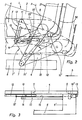
- the motor vehicle seat 1 shown in FIG. 1 consists of a seat part 2 and a backrest 3 articulated thereon.
- the seat part 2 is of a frame-like, roughly its rectangular contour
- Corresponding support element 4 is worn, on which in turn in the area of the front edge of the seat part 2 and in the area of the backrest 3 two articulated support levers 5 and 6 are articulated, the lower end portions of which are attached to a guide rail 8 which is longitudinally displaceably mounted on the vehicle floor via pivot bolts 7 are pivotally mounted.
- the seat part 2 and thus the backrest 3 is illustrated by the raised position a shown in FIGS.
- the support lever 6 lying in the region of the backrest 3 is articulated via a bearing pin 9 on the frame section of the support element 4 facing the vehicle exterior. Furthermore, in parallel distance to the support lever 6 on this via an intermediate part 6 'a pivot lever 10 is permanently attached, which includes an angle of about 40 ° with the support lever 6. Via a bearing pin 11, a triangular swivel plate 12 is further articulated on the support element 4, which has a longitudinal slot 13 which runs parallel to an outer edge and is directed towards the bearing pin 11, in which a guide pin 14 projecting from the free end portion of the swivel lever 10 engages in a longitudinally displaceable manner.
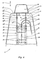
- Fig. 4 it can be seen that the headrest 18 which is arranged on the backrest 3 so as to be vertically displaceable is held by two spaced apart support rods 19 which are connected at their lower end via a cross member 20 and arranged in a backrest 3, thereby approximately parallel to the back of the extending guide frame 21 are guided vertically.
- This consists of two guide rails 22 which are U-shaped in cross section and each surround a support rod 19 and are connected via an overhead guide cross member 23 and a transverse connecting part 24 which is provided at a greater distance from the lowest position of the cross part 20.
- the through openings 23 'provided in the guide cross member 23' for carrying the support rods 19 can be designed such that they are guided in the guide cross member 23 when there are height shifts in the directions of the double arrow e.
- a connecting joint 25 is provided, with which the support rod sections 19 'attached to the headrest 18' are releasably connectable.
- Bowden cable 16 With its first end portion 16 'attached to the support member 4 Bowden cable 16 is attached with its second end portion 16 ⁇ to form a convex arc on the top 23 ⁇ of the guide cross member 23 as shown in FIG. 4.
- the wire rope 15 of the Bowden cable 16 is attached to the top of the cross member 20, while on the underside of a tension spring 26 is attached with its opposite end to the connecting part 24 with bias.
- the headrest 18 is pulled in the raised position a of the seat part 2 (Fig. 1 and 4) on its support rods 19 to the upper edge 3 'of the backrest 3. If the seat part 2 and thus the backrest 3 of the motor vehicle seat 1 is shifted into the lowered position b (dash-dotted lines), the guide pin 14 slides along the longitudinal slot 13 of the pivot plate 12 by pivoting the support lever 6 in the direction of arrow c and thereby pivots it from the in Fig. 2 with solid lines shown pivot position f in the pivot position shown with dash-dotted lines f '.
- the articulation point 15 'of the wire rope 15 of the Bowden cable 16 is shifted from its position in the raised position a of the seat part 2 to the front (arrow direction h), so that the end section engaging on the upper side of the transverse part 20 of the guide rods 19 of the headrest 18 also engages of the wire rope 15 is pulled against the action of the tension spring 26 upward (arrow direction h).
- the headrest 18 remains approximately in its original position m (when the seat part 2 is in the upright position), while the backrest 3 is moved downward between them Upper edge 3 'and the lower edge of the headrest 18 a distance k arises.
- the inside support lever 6 is designed as a one-leg pivot lever;
- the support lever 6 provided with the swivel lever 10 can also be provided on the inside of the motor vehicle seat 1 facing the longitudinal plane of the vehicle or in the central region of its width.
Landscapes
- Engineering & Computer Science (AREA)
- Aviation & Aerospace Engineering (AREA)
- Transportation (AREA)
- Mechanical Engineering (AREA)
- Seats For Vehicles (AREA)
Applications Claiming Priority (2)
| Application Number | Priority Date | Filing Date | Title |
|---|---|---|---|
| DE3831790 | 1988-09-19 | ||
| DE3831790A DE3831790A1 (de) | 1988-09-19 | 1988-09-19 | Sitz, insbesondere kraftfahrzeugsitz |
Publications (2)
| Publication Number | Publication Date |
|---|---|
| EP0359962A1 true EP0359962A1 (fr) | 1990-03-28 |
| EP0359962B1 EP0359962B1 (fr) | 1993-06-09 |
Family
ID=6363250
Family Applications (1)
| Application Number | Title | Priority Date | Filing Date |
|---|---|---|---|
| EP89114417A Expired - Lifetime EP0359962B1 (fr) | 1988-09-19 | 1989-08-04 | Siège, en particulier siège de véhicule automobile |
Country Status (2)
| Country | Link |
|---|---|
| EP (1) | EP0359962B1 (fr) |
| DE (2) | DE3831790A1 (fr) |
Cited By (10)
| Publication number | Priority date | Publication date | Assignee | Title |
|---|---|---|---|---|
| EP0754591A2 (fr) * | 1995-07-19 | 1997-01-22 | LEAR CORPORATION ITALIA S.p.A. | Siège de véhicule automobile |
| FR2749812A1 (fr) * | 1996-06-17 | 1997-12-19 | Faure Bertrand Equipements Sa | Siege avant de vehicule automobile avec appui-tete asservi |
| EP0826553A2 (fr) * | 1996-08-28 | 1998-03-04 | TRW Occupant Restraint Systems GmbH | Siège de véhicule à appui-tête, monté réglable sur le dossier |
| EP0819569A3 (fr) * | 1996-07-16 | 1998-11-11 | Gestind M.B. Manifattura Di Bruzolo S.P.A | Appui-tête pour sièges de véhicules automobiles |
| FR2777516A1 (fr) * | 1998-04-15 | 1999-10-22 | Faure Bertrand Equipements Sa | Siege de vehicule automobile comportant au moins un element reglable automatiquement en fonction de la position longitudinale du siege dans le vehicule |
| EP1038723A3 (fr) * | 1999-03-19 | 2001-01-17 | C.Rob. Hammerstein GmbH & Co.KG | Siège de véhicule avec un dispositif de déplacement longitudinal et un appui-tête |
| GB2359017A (en) * | 1997-09-10 | 2001-08-15 | Autoliv Dev | A vehicle seat head-rest |
| NL1018170C2 (nl) * | 2001-04-25 | 2002-10-29 | Whiplash Preventie Systems Hol | Stoel met ten opzichte van de zitting verplaatsbare rugleuning en daarin toe te passen verplaatsingsinrichting. |
| FR2860461A1 (fr) * | 2003-10-07 | 2005-04-08 | Renault Sa | Ensemble de dossier de siege pour vehicule automobile |
| WO2010043030A1 (fr) * | 2008-10-14 | 2010-04-22 | Magna Seating Inc. | Appuie-tête et poignée plate de rangement de siège |
Families Citing this family (8)
| Publication number | Priority date | Publication date | Assignee | Title |
|---|---|---|---|---|
| DE3843616A1 (de) * | 1988-12-23 | 1990-06-28 | Bayerische Motoren Werke Ag | Sitz, insbesondere kraftfahrzeugsitz |
| DE3843617A1 (de) * | 1988-12-23 | 1990-06-28 | Bayerische Motoren Werke Ag | Sitz, insbesondere fuer ein kraftfahrzeug |
| DE4319120A1 (de) * | 1993-06-09 | 1994-12-15 | Bayerische Motoren Werke Ag | Sitz, insbesondere Kraftfahrzeugsitz |
| DE19513705C5 (de) * | 1995-04-11 | 2005-09-08 | Lear Corp., Southfield | Längseinstellbarer Fahrzeugsitz |
| DE19631843A1 (de) * | 1996-08-07 | 1998-02-12 | Bayerische Motoren Werke Ag | Fahrzeugsitz mit einer Kopfstütze |
| DE19726795B4 (de) * | 1997-06-24 | 2004-10-21 | Faurecia Autositze Gmbh & Co. Kg | Kraftfahrzeugsitz mit höhenverstellbarer Kopfstütze |
| DE19746736C2 (de) * | 1997-10-13 | 2000-01-20 | Brose Fahrzeugteile | Vorrichtung zur Einstellung einer Kopfstütze an einem Fahrzeugsitz |
| DE19832902C2 (de) * | 1998-07-22 | 2002-09-05 | Grammer Ag | Fahrzeugsitz mit einer Kopfstütze |
Citations (4)
| Publication number | Priority date | Publication date | Assignee | Title |
|---|---|---|---|---|
| US3311413A (en) * | 1964-07-17 | 1967-03-28 | Anderson Co | Headrest positioning mechanism |
| DE2447874A1 (de) * | 1974-10-08 | 1976-04-22 | Volkswagenwerk Ag | Sicherheitseinrichtung |
| DE2810577A1 (de) * | 1978-03-11 | 1979-09-20 | Volkswagenwerk Ag | Fahrzeug, insbesondere personenkraftfahrzeug |
| DE3034828A1 (de) * | 1980-09-16 | 1982-04-29 | Bremshey Ag, 5650 Solingen | Sitz, insbesondere fahrgastsitz |
Family Cites Families (1)
| Publication number | Priority date | Publication date | Assignee | Title |
|---|---|---|---|---|
| DE3634500A1 (de) * | 1986-02-10 | 1987-08-20 | Wilfried Prof Dr Me Diebschlag | Sitz, insbesondere autositz |
-
1988
- 1988-09-19 DE DE3831790A patent/DE3831790A1/de active Granted
-
1989
- 1989-08-04 EP EP89114417A patent/EP0359962B1/fr not_active Expired - Lifetime
- 1989-08-04 DE DE8989114417T patent/DE58904615D1/de not_active Expired - Fee Related
Patent Citations (4)
| Publication number | Priority date | Publication date | Assignee | Title |
|---|---|---|---|---|
| US3311413A (en) * | 1964-07-17 | 1967-03-28 | Anderson Co | Headrest positioning mechanism |
| DE2447874A1 (de) * | 1974-10-08 | 1976-04-22 | Volkswagenwerk Ag | Sicherheitseinrichtung |
| DE2810577A1 (de) * | 1978-03-11 | 1979-09-20 | Volkswagenwerk Ag | Fahrzeug, insbesondere personenkraftfahrzeug |
| DE3034828A1 (de) * | 1980-09-16 | 1982-04-29 | Bremshey Ag, 5650 Solingen | Sitz, insbesondere fahrgastsitz |
Cited By (16)
| Publication number | Priority date | Publication date | Assignee | Title |
|---|---|---|---|---|
| EP0754591A2 (fr) * | 1995-07-19 | 1997-01-22 | LEAR CORPORATION ITALIA S.p.A. | Siège de véhicule automobile |
| EP0754591A3 (fr) * | 1995-07-19 | 1997-07-09 | Lear Corp Italia Spa | Siège de véhicule automobile |
| FR2749812A1 (fr) * | 1996-06-17 | 1997-12-19 | Faure Bertrand Equipements Sa | Siege avant de vehicule automobile avec appui-tete asservi |
| EP0819569A3 (fr) * | 1996-07-16 | 1998-11-11 | Gestind M.B. Manifattura Di Bruzolo S.P.A | Appui-tête pour sièges de véhicules automobiles |
| EP0826553A2 (fr) * | 1996-08-28 | 1998-03-04 | TRW Occupant Restraint Systems GmbH | Siège de véhicule à appui-tête, monté réglable sur le dossier |
| EP0826553A3 (fr) * | 1996-08-28 | 1998-12-02 | TRW Occupant Restraint Systems GmbH & Co. KG | Siège de véhicule à appui-tête, monté réglable sur le dossier |
| GB2359017A (en) * | 1997-09-10 | 2001-08-15 | Autoliv Dev | A vehicle seat head-rest |
| GB2359017B (en) * | 1997-09-10 | 2002-02-20 | Autoliv Dev | A vehicle seat |
| FR2777516A1 (fr) * | 1998-04-15 | 1999-10-22 | Faure Bertrand Equipements Sa | Siege de vehicule automobile comportant au moins un element reglable automatiquement en fonction de la position longitudinale du siege dans le vehicule |
| EP1038723A3 (fr) * | 1999-03-19 | 2001-01-17 | C.Rob. Hammerstein GmbH & Co.KG | Siège de véhicule avec un dispositif de déplacement longitudinal et un appui-tête |
| NL1018170C2 (nl) * | 2001-04-25 | 2002-10-29 | Whiplash Preventie Systems Hol | Stoel met ten opzichte van de zitting verplaatsbare rugleuning en daarin toe te passen verplaatsingsinrichting. |
| WO2002085664A3 (fr) * | 2001-04-25 | 2003-01-03 | Whiplash Preventie Systems Hol | Siege a dossier mobile sur l'assise et dispositif mecanique a cet effet |
| FR2860461A1 (fr) * | 2003-10-07 | 2005-04-08 | Renault Sa | Ensemble de dossier de siege pour vehicule automobile |
| WO2005032880A3 (fr) * | 2003-10-07 | 2005-07-21 | Renault Sa | Ensemble de dossier de siege pour vehicule automobile |
| WO2010043030A1 (fr) * | 2008-10-14 | 2010-04-22 | Magna Seating Inc. | Appuie-tête et poignée plate de rangement de siège |
| US8459731B2 (en) | 2008-10-14 | 2013-06-11 | Magna Seating Inc. | Head restraint and seat stow flat handle |
Also Published As
| Publication number | Publication date |
|---|---|
| DE58904615D1 (de) | 1993-07-15 |
| DE3831790C2 (fr) | 1990-08-23 |
| EP0359962B1 (fr) | 1993-06-09 |
| DE3831790A1 (de) | 1990-03-22 |
Similar Documents
| Publication | Publication Date | Title |
|---|---|---|
| DE3831790C2 (fr) | ||
| DE60300049T2 (de) | Kopfstütze für Kraftfahrzeugsitze | |
| EP0001230B1 (fr) | Cabine de conduite habitable pour véhicules de transport à longue distance | |
| DE3940839C1 (fr) | ||
| EP0099095A2 (fr) | Siège de véhicule avec appuie-cuisse réglable | |
| EP1201475A2 (fr) | Dispositif pare-vent | |
| DE2522074B2 (de) | Feststellvorrichtung für die Gleitführung eines in Längsrichtung verschiebbaren Kfz-Sitzes | |
| DE2940463A1 (de) | In sitzlaengsrichtung verstellbarer automobilsitz | |
| EP1578631B1 (fr) | Cabriolet comportant un toit mobile | |
| DE3136651C2 (de) | Schalensitz für Kraftfahrzeuge | |
| EP2161175B1 (fr) | Pont d'un passage doté d'un soufflet entre deux véhicules reliés ensemble de manière articulée, par exemple d'un véhicule sur rail | |
| DE1919350A1 (de) | Einrichtung fuer Scheibenwischerarme | |
| EP0831001A1 (fr) | Rancher pour une bache | |
| DE10216893C1 (de) | Kraftfahrzeug, insbesondere Personenwagen, mit einem Verdeck | |
| EP2767442B1 (fr) | Dispositif de protection de soutènement d'un véhicule utilitaire et véhicule utilitaire équipé d'un tel dispositif | |
| DE102012104812B4 (de) | Kraftfahrzeug mit einem feststehenden Überrollbügel | |
| DE3425273A1 (de) | Gleitschuh fuer ein fahrzeug-schiebedach | |
| DE3940491C1 (en) | Step flap for vehicle ramp - has adaptor with support to bear on ramp when latter pulled out for use | |
| DE3843617C2 (fr) | ||
| EP1851086A1 (fr) | Siege de vehicule | |
| DE3838656C2 (fr) | ||
| DE2833953C2 (de) | Vorrichtung zum Verringern des Luftwiderstandes eines Lastkraftwagens | |
| DE3420418C2 (fr) | ||
| EP0043529B1 (fr) | Siège de véhicule, en particulier siège rabattable pour véhicule agricole | |
| EP0970843A1 (fr) | Structure de siège avec fonction de rabattement pour siège d'automobile |
Legal Events
| Date | Code | Title | Description |
|---|---|---|---|
| PUAI | Public reference made under article 153(3) epc to a published international application that has entered the european phase |
Free format text: ORIGINAL CODE: 0009012 |
|
| AK | Designated contracting states |
Kind code of ref document: A1 Designated state(s): DE FR GB IT SE |
|
| 17P | Request for examination filed |
Effective date: 19900329 |
|
| 17Q | First examination report despatched |
Effective date: 19920701 |
|
| GRAA | (expected) grant |
Free format text: ORIGINAL CODE: 0009210 |
|
| RAP3 | Party data changed (applicant data changed or rights of an application transferred) |
Owner name: BAYERISCHE MOTOREN WERKE AKTIENGESELLSCHAFT |
|
| AK | Designated contracting states |
Kind code of ref document: B1 Designated state(s): DE FR GB IT SE |
|
| GBT | Gb: translation of ep patent filed (gb section 77(6)(a)/1977) |
Effective date: 19930608 |
|
| ET | Fr: translation filed | ||
| REF | Corresponds to: |
Ref document number: 58904615 Country of ref document: DE Date of ref document: 19930715 |
|
| ITF | It: translation for a ep patent filed |
Owner name: STUDIO JAUMANN |
|
| PLBE | No opposition filed within time limit |
Free format text: ORIGINAL CODE: 0009261 |
|
| STAA | Information on the status of an ep patent application or granted ep patent |
Free format text: STATUS: NO OPPOSITION FILED WITHIN TIME LIMIT |
|
| 26N | No opposition filed | ||
| PGFP | Annual fee paid to national office [announced via postgrant information from national office to epo] |
Ref country code: GB Payment date: 19940802 Year of fee payment: 6 |
|
| PGFP | Annual fee paid to national office [announced via postgrant information from national office to epo] |
Ref country code: SE Payment date: 19940831 Year of fee payment: 6 |
|
| EAL | Se: european patent in force in sweden |
Ref document number: 89114417.2 |
|
| PG25 | Lapsed in a contracting state [announced via postgrant information from national office to epo] |
Ref country code: GB Effective date: 19950804 |
|
| PG25 | Lapsed in a contracting state [announced via postgrant information from national office to epo] |
Ref country code: SE Effective date: 19950805 |
|
| PGFP | Annual fee paid to national office [announced via postgrant information from national office to epo] |
Ref country code: FR Payment date: 19950831 Year of fee payment: 7 |
|
| GBPC | Gb: european patent ceased through non-payment of renewal fee |
Effective date: 19950804 |
|
| EUG | Se: european patent has lapsed |
Ref document number: 89114417.2 |
|
| PG25 | Lapsed in a contracting state [announced via postgrant information from national office to epo] |
Ref country code: FR Effective date: 19970430 |
|
| REG | Reference to a national code |
Ref country code: FR Ref legal event code: ST |
|
| PGFP | Annual fee paid to national office [announced via postgrant information from national office to epo] |
Ref country code: DE Payment date: 20000927 Year of fee payment: 12 |
|
| PG25 | Lapsed in a contracting state [announced via postgrant information from national office to epo] |
Ref country code: DE Free format text: LAPSE BECAUSE OF NON-PAYMENT OF DUE FEES Effective date: 20020501 |
|
| PG25 | Lapsed in a contracting state [announced via postgrant information from national office to epo] |
Ref country code: IT Free format text: LAPSE BECAUSE OF NON-PAYMENT OF DUE FEES;WARNING: LAPSES OF ITALIAN PATENTS WITH EFFECTIVE DATE BEFORE 2007 MAY HAVE OCCURRED AT ANY TIME BEFORE 2007. THE CORRECT EFFECTIVE DATE MAY BE DIFFERENT FROM THE ONE RECORDED. Effective date: 20050804 |