EP1578631B1 - Cabriolet comportant un toit mobile - Google Patents
Cabriolet comportant un toit mobile Download PDFInfo
- Publication number
- EP1578631B1 EP1578631B1 EP03813531A EP03813531A EP1578631B1 EP 1578631 B1 EP1578631 B1 EP 1578631B1 EP 03813531 A EP03813531 A EP 03813531A EP 03813531 A EP03813531 A EP 03813531A EP 1578631 B1 EP1578631 B1 EP 1578631B1
- Authority
- EP
- European Patent Office
- Prior art keywords
- hinge
- vehicle according
- cabriolet vehicle
- intermediate lever
- beam part
- Prior art date
- Legal status (The legal status is an assumption and is not a legal conclusion. Google has not performed a legal analysis and makes no representation as to the accuracy of the status listed.)
- Expired - Lifetime
Links
- 239000000969 carrier Substances 0.000 description 9
- 239000004744 fabric Substances 0.000 description 5
- 101100498160 Mus musculus Dach1 gene Proteins 0.000 description 2
- 238000006073 displacement reaction Methods 0.000 description 2
- 229920003023 plastic Polymers 0.000 description 2
- 239000004033 plastic Substances 0.000 description 2
- 241000282346 Meles meles Species 0.000 description 1
- 238000004026 adhesive bonding Methods 0.000 description 1
- 238000010276 construction Methods 0.000 description 1
- 229920002635 polyurethane Polymers 0.000 description 1
- 239000004814 polyurethane Substances 0.000 description 1
- 239000007787 solid Substances 0.000 description 1
- 229920001187 thermosetting polymer Polymers 0.000 description 1
- 238000003466 welding Methods 0.000 description 1
Images


Classifications
-
- B—PERFORMING OPERATIONS; TRANSPORTING
- B60—VEHICLES IN GENERAL
- B60J—WINDOWS, WINDSCREENS, NON-FIXED ROOFS, DOORS, OR SIMILAR DEVICES FOR VEHICLES; REMOVABLE EXTERNAL PROTECTIVE COVERINGS SPECIALLY ADAPTED FOR VEHICLES
- B60J7/00—Non-fixed roofs; Roofs with movable panels, e.g. rotary sunroofs
- B60J7/08—Non-fixed roofs; Roofs with movable panels, e.g. rotary sunroofs of non-sliding type, i.e. movable or removable roofs or panels, e.g. let-down tops or roofs capable of being easily detached or of assuming a collapsed or inoperative position
- B60J7/12—Non-fixed roofs; Roofs with movable panels, e.g. rotary sunroofs of non-sliding type, i.e. movable or removable roofs or panels, e.g. let-down tops or roofs capable of being easily detached or of assuming a collapsed or inoperative position foldable; Tensioning mechanisms therefor, e.g. struts
- B60J7/1226—Soft tops for convertible vehicles
- B60J7/1234—Soft tops for convertible vehicles characterised by arches, e.g. shape or material
-
- B—PERFORMING OPERATIONS; TRANSPORTING
- B60—VEHICLES IN GENERAL
- B60J—WINDOWS, WINDSCREENS, NON-FIXED ROOFS, DOORS, OR SIMILAR DEVICES FOR VEHICLES; REMOVABLE EXTERNAL PROTECTIVE COVERINGS SPECIALLY ADAPTED FOR VEHICLES
- B60J7/00—Non-fixed roofs; Roofs with movable panels, e.g. rotary sunroofs
- B60J7/08—Non-fixed roofs; Roofs with movable panels, e.g. rotary sunroofs of non-sliding type, i.e. movable or removable roofs or panels, e.g. let-down tops or roofs capable of being easily detached or of assuming a collapsed or inoperative position
- B60J7/12—Non-fixed roofs; Roofs with movable panels, e.g. rotary sunroofs of non-sliding type, i.e. movable or removable roofs or panels, e.g. let-down tops or roofs capable of being easily detached or of assuming a collapsed or inoperative position foldable; Tensioning mechanisms therefor, e.g. struts
- B60J7/1226—Soft tops for convertible vehicles
- B60J7/1265—Soft tops for convertible vehicles characterised by kinematic movements, e.g. using parallelogram linkages
Definitions
- the invention relates to a convertible vehicle having a movable roof which is flexible at least in some areas and has a roof covering stretched over at least partially rigid support, wherein the supports each have at least one joint on which a first support part pivotable about a hinge axis with a second Carrier part is connected.
- Such a convertible vehicle is known from FR 2814403 A from DE 101 23 227. Although the construction described in DE 101 23 227 has proven itself, it can lead to excessive stresses in the roof cover when opening and closing. In addition, the tops of the side members are in the region of the pivot axis directly to each other, which is disadvantageous in curved carriers with respect to the space required in the folded state.
- the object of the invention is to improve a convertible vehicle of the type mentioned in view of the disadvantages described above.
- the intermediate lever is arranged within the contour of the carrier parts when the extension of the first and second carrier part (closed roof) is aligned.
- the hinge axis and / or the further hinge axis is arranged in a closed roof or edge region of the joint.
- the intermediate lever with respect to a pivoting movement about the hinge axis and / or the further hinge axis (each) cooperates with a stop for limiting the pivoting range.
- first and / or the second support member relative to the intermediate lever can be pivoted by approximately 90 °.
- the intermediate lever is provided with at least one stop, which is preferably designed as a nose-shaped extension of the intermediate lever.
- the intermediate lever is pivotally connected to the hinge axis with a (first) hinge part, that is slidably received in the second carrier part
- the (first) hinge part is slide-movable along a longitudinal axis of the second carrier part.
- the (first) hinge part is slidably movable at an angle to a longitudinal axis of the second carrier, wherein a distance between the hinge axis and the longitudinal axis of the second carrier part changes upon displacement of the (first) hinge part.
- the (first) joint part along a predetermined trajectory in the second carrier part is displaceable, wherein a distance between the hinge axis and a longitudinal axis of the second carrier part changes upon displacement of the (first) joint part in a predetermined manner.
- the (first) hinge part is biased by at least one return spring, in particular tension spring or drawstring, in a starting position in the second carrier part.
- the invention further provides that the intermediate lever on its side facing the sliding (first) hinge part has an angled extension to which the return spring is attached
- hinge axes are formed by bolts which are received in bores in the support parts and the (first) hinge part.
- the carrier parts are mutually pivotable up to about 180 °.
- the joint is connected via a second joint part with the first support part, wherein the second joint part can be slidably movably received in the first support part.
- Due to the intermediate lever a defined end position is achieved with a mutual distance of the longitudinal support elements in the pivoted position, so that a gap between the carriers is formed, in which the top fabric is receivable.
- the tension spring engages an angled portion of the intermediate lever, one obtains a defined pivoting sequence about the hinge axes of the intermediate lever, whereby the opening or closing operation of the roof is simplified and improved.
- the invention also advantageously allows for displaceably arranged hinge part avoiding excessive stresses in the top cloth and in the carriers (Faltgestlinde). If, as provided for advantageous is, all kinematic components are included within the longitudinal beam elements, a minimal space or space requirement is achieved. When using a tension spring a defined position of the components is achieved to each other.
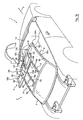
- the convertible vehicle 1 shown schematically in FIGS. 1 a and 1 b has an overall movable roof 2, which comprises a rigid rear roof part 3 and a flexible roof part 4 adjoining it in the direction of travel F.
- the roof 2 can be designed to be flexible overall. An over the roof stretched roof cover is not shown.
- the flexible roof part 4 has vehicle edge side frame supports 6, 8 and support 10, 12, wherein for simplicity of the description present, the frame supports are also referred to as a carrier.
- the carriers 6 to 12 are arranged in the illustrated embodiment in the vehicle longitudinal direction and connect the rigid roof part 3 with an upper portion of a front windshield frame 14.
- a different number and in particular (in addition or only) a middle carrier lying in the vertical vehicle longitudinal center plane may be provided.
- transverse braces (not shown) may be foldable.
- transverse connectors 16, 17 are provided between the carriers 10, 12.
- Such cross connectors may also be provided between the (middle) supports 10, 12 and (lateral) supports or frame supports 6, 8.
- the cross connectors run just below the top of the carrier, so that they do not appear in the roof cover with the roof closed.
- All carriers 6 to 12 are connected to each other via a front cross member 19 which serves to bear against the windshield frame 14.
- the longitudinal beams 6, 8, 10, 12 are in the illustrated embodiment in each case by three joints 18a, 18b, 18c in their longitudinal course in four sections 6a, b, c, d; 8a, b, c, d; 10a, b, c, d and 12a, b, c, d divided.
- the flexible roof part 4 is foldable about these joints, as indicated in Fig. 1b.
- each associated with respect to a folding movement joints 18a, 18b, 18c is coordinated so that the said joints are each moved simultaneously.
- the juxtaposed joints, for example, 18a are not on a common straight transverse line, but their position is matched by the curvature and the movement of the opening and closing of the roof to each other. This sequence of movements is known, for example, from DE 101 23 227.
- Fig. 2 to 6 show the structure and function of the joints 18a, b, c, d, wherein the individual joints of a roof with respect to specific individual dimensions, etc. may possibly be quite different from each other.
- the carriers 6, 8, 10, 12 may, for example, consist of a plastic, in particular of a mechanically highly resilient plastic such as a thermoset, such as polyurethane.
- the carriers are essentially of a similar design and each comprise a hollow or solid profile, for example a triangular profile (FIG. 6).
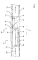
- FIG. 2 shows by way of example a joint 18a arranged within the carrier 10 in a starting position which corresponds to a closed position of the roof (FIG. 1a) and in which the carrier parts 10a, 10b are aligned with respect to their longitudinal axes 20a, 20b.
- the second or in the direction of travel F seen front support member 10b has a longitudinal guide 22 in the longitudinal axis 20b longitudinally displaceably received and guided first joint part 24 on which pivotable about a hinge axis 26, the rear, first support member 10a is articulated.
- the first carrier part 10a is not directly articulated in the illustrated preferred embodiment on the hinge axis 26, but via an associated with the hinge axis 26 intermediate lever 28 which in turn via a further hinge axis 30 pivotally connected to the first support member 10a connected is.
- the joint axes 26, 30 are arranged in the upper region of the carrier 10, and the longitudinal guide 22 is executed due to its triangular cross-sectional shape (Fig. 6) against rotation.
- connection of the intermediate lever 28 to the first or rear support part 10a is expediently also formed by a support member 10a separately executed second or rear hinge part 32, which is inserted into the support member formed as a hollow carrier profile 10a and there by welding, clamps, screws or gluing can be attached, with the advantage that the carrier can be designed as a simple drawn tube.
- any other profile cross-section for the carrier 10 or the other carriers is of course conceivable, for example a round tube, rectangular tube or special shapes.
- the second hinge part 32 is not rigid, but like the first hinge part 24 is received longitudinally displaceable in the support member 10 a.
- the intermediate lever 28 has on its the first support part 10a side facing a narrow nose-shaped extension 34 and on its the first hinge part 24 and the second support member 10b side facing an angled, at about 45 ° to the longitudinal direction of the intermediate lever downwardly facing lever-like extension 36, at the end via a first pin connection 38, a tension spring 40 (or a drawstring) is attached.
- the tension spring 40 is connected to a second pin or Bolt 41 attached to the front support member 10b.
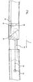
- a pivoting movement takes place about the further articulation axis 30 of the intermediate lever 28 with the rear support part 10a (FIG. 4).
- a rotational movement about the hinge axis 26 of the intermediate lever 28 with the front support part 10b and the (first) hinge part 24 is avoided due to the tensile force of the tension spring in connection with the arrangement of the connection points of the tension spring described above.
- the first pivoting movement is continued until the nose-shaped extension 34 of the intermediate lever 28 reaches a stop 42 within the rear support part 10a. In this position (FIG. 4), the intermediate lever 28 is approximately perpendicular to the rear support part 10a.
- the front support member 10b pivots about the hinge axis 30 with the intermediate lever against the tensile force of the tension spring 40, while the length (distance of the connection points 38, 41) increases.
- This pivotal movement is continued (FIG. 5) until a stop surface 44 abuts a recess for the intermediate lever 28 in the front support part 10b or in the joint part 24 against the intermediate lever 28 (FIGS. 5, 6).
- the front and rear support part are now approximately parallel to each other at a defined distance from each other. In a space formed therebetween intermediate space 46, the folded top cloth can be added.
Landscapes
- Engineering & Computer Science (AREA)
- Mechanical Engineering (AREA)
- Body Structure For Vehicles (AREA)
- Fittings On The Vehicle Exterior For Carrying Loads, And Devices For Holding Or Mounting Articles (AREA)
- Superstructure Of Vehicle (AREA)
Abstract
Claims (15)
- Véhicule cabriolet avec un toit mobile (4), lequel est formé au moins en zones flexibles et présente un revêtement de toit tendu sur des supports au moins en zones rigides (6, 8, 10, 12), les supports (6, 8, 10, 12) présentant chacun au moins une articulation (18a, b, c), à laquelle est reliée de façon directe ou indirecte une première partie de support (10a) à une deuxième partie de support (10b) par le biais d'un axe articulé (26) de façon à pouvoir pivoter de manière angulaire, au moins une articulation (18a) présentant un levier intermédiaire (28), lequel est relié de façon à pouvoir pivoter à la deuxième partie de support (10b) par le biais de l'essieu articulé (26) et de façon à pouvoir tourner à la première partie de support (10a) par le biais d'un axe supplémentaire (30) éloigné de l'axe articulé (26) caractérisé en ce que le levier intermédiaire (28) est relié de façon indirecte à la deuxième partie de support, grâce à quoi il est relié de façon à pouvoir pivoter à une partie articulée (24) au niveau de l'essieu articulé (26), laquelle est reçue dans la deuxième partie de support (10b) mobile de façon coulissante.
- Véhicule cabriolet selon la revendication 1, caractérisé en ce que le levier intermédiaire (28) est arrangé à l'intérieur d'un contour des parties de support (10a, 10b), la première (10a) et la deuxième (10b) partie de support s'étendant de façon alignée.
- Véhicule cabriolet selon la revendication 1 ou la revendication 2, caractérisé en ce que l'axe articulé (26) et/ou l'axe articulé supplémentaire (30) est arrangé dans une zone de bord supérieure de l'articulation (18a), le toit étant fermé.
- Véhicule cabriolet selon l'une des revendications précédentes, caractérisé en ce que le levier intermédiaire (28) coopère avec une butée (42, 44) pour limiter l'étendue de pivotement relativement à un mouvement pivotant autour de l'axe articulé (26) et/ou de l'axe articulé supplémentaire (30).
- Véhicule cabriolet selon l'une des revendications précédentes, caractérisé en ce que la première (10a) et/ou la deuxième partie de support (10b) peut pivoter d'environ 90° par rapport au levier intermédiaire (28).
- Véhicule cabriolet selon l'une des revendications précédentes, caractérisé en ce que le levier intermédiaire (28) est pourvu d'au moins une butée, laquelle est formée de préférence comme un prolongement en forme de nez (34) du levier intermédiaire (28).
- Véhicule cabriolet selon l'une des revendications précédentes, caractérisé en ce que la partie articulée (24) est mobile de façon coulissante le long d'un axe longitudinal (20b) de la deuxième partie de support (10b).
- Véhicule cabriolet selon l'une des revendications 1 à 6, caractérisé en ce que la partie articulée (24) est mobile de façon coulissante sur un angle par rapport à un axe longitudinal (20b) de la deuxième partie de support (10b), grâce à quoi une distance entre l'essieu articulé (26) et l'axe longitudinal (20b) de la deuxième partie de support (10b) varie lorsque la partie de support (24) est déplacée.
- Véhicule cabriolet selon l'une des revendications précédentes, caractérisé en ce que la partie articulée (24) peut être déplacée le long d'une trajectoire prédéterminée dans la deuxième partie de support (10b), grâce à quoi une distance entre l'axe articulé (26) et un axe longitudinal (20b) de la deuxième partie de support (10b) varie lorsque la partie de support (24) est déplacée.
- Véhicule cabriolet selon l'une des revendications précédentes, caractérisé en ce que la partie articulée (24) est décalée en direction d'une position initiale dans la deuxième partie de support (10b) par au moins un ressort de rappel (40), en particulier un ressort de traction ou un tirant.
- Véhicule cabriolet selon l'une des revendications précédentes, caractérisé en ce que le levier intermédiaire (28) présente, sur son côté faisant face à la partie articulée mobile de façon coulissante (24), un prolongement coudé (36) auquel est attaché le ressort de rappel (40).
- Véhicule cabriolet selon l'une des revendications précédentes, caractérisé en ce que les axes articulés (26, 30) sont construits à l'aide de boulons, lesquels sont reçus dans des alésages dans les parties de support (10a, 10b) et dans la partie articulée (24).
- Véhicule cabriolet selon l'une des revendications précédentes, caractérisé en ce que les parties de support (10a, 10b) peuvent pivoter l'une par rapport à l'autre jusqu'à environ 180°.
- Véhicule cabriolet selon l'une des revendications précédentes, caractérisé en ce que l'articulation (18a) est reliée à la première partie de support (10a) par le biais d'une deuxième partie articulée.
- Véhicule cabriolet selon la revendication 14, caractérisé en ce que la deuxième partie articulée est reçue mobile de façon coulissante dans la première partie de support (10a).
Applications Claiming Priority (3)
| Application Number | Priority Date | Filing Date | Title |
|---|---|---|---|
| DE2002159864 DE10259864A1 (de) | 2002-12-20 | 2002-12-20 | Cabriolet-Fahrzeug mit einem beweglichen Dach |
| DE10259864 | 2002-12-20 | ||
| PCT/DE2003/004109 WO2004056596A2 (fr) | 2002-12-20 | 2003-12-12 | Cabriolet comportant un toit mobile |
Publications (2)
| Publication Number | Publication Date |
|---|---|
| EP1578631A2 EP1578631A2 (fr) | 2005-09-28 |
| EP1578631B1 true EP1578631B1 (fr) | 2006-04-26 |
Family
ID=32519170
Family Applications (1)
| Application Number | Title | Priority Date | Filing Date |
|---|---|---|---|
| EP03813531A Expired - Lifetime EP1578631B1 (fr) | 2002-12-20 | 2003-12-12 | Cabriolet comportant un toit mobile |
Country Status (4)
| Country | Link |
|---|---|
| EP (1) | EP1578631B1 (fr) |
| AU (1) | AU2003296532A1 (fr) |
| DE (2) | DE10259864A1 (fr) |
| WO (1) | WO2004056596A2 (fr) |
Families Citing this family (16)
| Publication number | Priority date | Publication date | Assignee | Title |
|---|---|---|---|---|
| WO2005061253A1 (fr) * | 2003-12-19 | 2005-07-07 | Ferrari S.P.A. | Vehicule automobile pourvu d'une capote escamotable |
| ITBO20040465A1 (it) | 2004-07-23 | 2004-10-23 | Ferrari Spa | Telaio di un automobile provvisto di moduli in materiale composito prodotti con tecnologia rtm |
| DE102009042236A1 (de) * | 2009-09-18 | 2011-03-31 | Magna Car Top Systems Gmbh | Faltverdeck für einen Personenkraftwagen |
| US10696146B2 (en) | 2013-04-02 | 2020-06-30 | Bestop, Inc. | Front top assembly for SUV |
| US9931921B2 (en) | 2013-04-02 | 2018-04-03 | Bestop, Inc. | Soft front cockpit cover |
| US9539888B2 (en) | 2013-04-02 | 2017-01-10 | Bestop, Inc. | Soft front cockpit cover |
| US9139073B2 (en) | 2013-04-02 | 2015-09-22 | Magna International Inc. | Soft front cockpit cover |
| US9944155B2 (en) | 2014-03-26 | 2018-04-17 | Bestop, Inc. | Lift assist mechanism for soft top |
| US10166848B2 (en) | 2015-11-17 | 2019-01-01 | Bestop, Inc. | Locking lift assist for folding soft tops |
| US10913338B2 (en) | 2015-11-17 | 2021-02-09 | Bestop, Inc. | Lift assist lock-down for a soft top |
| US10414253B2 (en) | 2016-05-13 | 2019-09-17 | Bestop, Inc. | Sliding / folding slanted back soft top assembly for SUV |
| US10603994B2 (en) | 2016-05-13 | 2020-03-31 | Bestop, Inc. | Slanted back soft top assembly for SUV |
| US10639975B2 (en) | 2016-05-13 | 2020-05-05 | Bestop, Inc. | Sliding soft top |
| US10449843B2 (en) | 2016-05-13 | 2019-10-22 | Bestop, Inc. | Folding soft top with lift assist |
| US10583720B2 (en) | 2016-05-13 | 2020-03-10 | Bestop, Inc. | Folding slanted back soft top assembly for SUV |
| US10618394B2 (en) | 2017-04-20 | 2020-04-14 | Bestop, Inc. | Removable door surround for a folding soft top |
Family Cites Families (4)
| Publication number | Priority date | Publication date | Assignee | Title |
|---|---|---|---|---|
| US5080428A (en) * | 1989-12-27 | 1992-01-14 | Rouland Paul K | Foldable roof assembly for vehicles having a TARGA top |
| WO1995029073A1 (fr) * | 1994-04-20 | 1995-11-02 | Karl Bauhof | Toit ouvrant pour automobiles |
| FR2814403B1 (fr) * | 2000-09-28 | 2002-11-29 | France Design | Toit escamotable dans le coffre arriere d'un vehicule |
| DE10123227B4 (de) * | 2001-05-12 | 2005-03-17 | Wilhelm Karmann Gmbh | Cabriolet-Fahrzeug mit einem zumindest bereichsweise flexiblen Dach |
-
2002
- 2002-12-20 DE DE2002159864 patent/DE10259864A1/de not_active Withdrawn
-
2003
- 2003-12-12 AU AU2003296532A patent/AU2003296532A1/en not_active Abandoned
- 2003-12-12 EP EP03813531A patent/EP1578631B1/fr not_active Expired - Lifetime
- 2003-12-12 DE DE50303145T patent/DE50303145D1/de not_active Expired - Lifetime
- 2003-12-12 WO PCT/DE2003/004109 patent/WO2004056596A2/fr not_active Application Discontinuation
Also Published As
| Publication number | Publication date |
|---|---|
| DE50303145D1 (de) | 2006-06-01 |
| DE10259864A1 (de) | 2004-07-15 |
| EP1578631A2 (fr) | 2005-09-28 |
| WO2004056596A2 (fr) | 2004-07-08 |
| AU2003296532A1 (en) | 2004-07-14 |
| WO2004056596A3 (fr) | 2004-08-19 |
Similar Documents
| Publication | Publication Date | Title |
|---|---|---|
| EP1578631B1 (fr) | Cabriolet comportant un toit mobile | |
| EP1197368B1 (fr) | Couvercle multi-pièce pour véhicule | |
| DE10063152B4 (de) | Klappdachwagen | |
| DE4100240C1 (fr) | ||
| DE3925150C2 (fr) | ||
| DE69108368T2 (de) | Schwenkschiebetür für Fahrzeuge. | |
| EP1080966A2 (fr) | Capote pour cabriolet | |
| DE10333781B4 (de) | Öffnungsfähiges Fahrzeugdach | |
| DE102004061758B4 (de) | Windstopeinrichtung | |
| WO2007025502A1 (fr) | Structure de toit pour vehicules automobiles | |
| EP0359962A1 (fr) | Siège, en particulier siège de véhicule automobile | |
| DE3328294C2 (de) | Klappverdeck für Fahrzeuge, insbesondere Kraftfahrzeuge | |
| EP1990223B1 (fr) | Capote d'un véhicule cabriolet | |
| EP3081418B1 (fr) | Dispositif pare-vent | |
| DE19942429A1 (de) | Schwenkantrieb für einen vorderen seitlichen Dachlenker eines Fahrzeugdaches oder Cabrioletverdecks | |
| DE19962995B4 (de) | Cabriolet-Fahrzeug mit einem zumindest bereichsweise flexiblen Dach | |
| EP1578630B1 (fr) | Vehicule de type cabriolet a toit mobile | |
| DE19737970A1 (de) | Versenkbares Klappdach für Fahrzeuge mit einem Überrollschutz | |
| EP0885760B1 (fr) | Capote pliante pour véhicule convertible | |
| DE3528817C2 (fr) | ||
| EP1110782B1 (fr) | Véhicule convertible avec au moins un toit ayant des regions flexible et au moins un joint perpendiculaire pour le support de celui | |
| DE102013111566A1 (de) | Windabweiser | |
| WO2004037575A2 (fr) | Vehicule automobile | |
| DE60225950T2 (de) | Schiebetüren mit Betätigungsmechanismus | |
| WO2004045881A1 (fr) | Automobile |
Legal Events
| Date | Code | Title | Description |
|---|---|---|---|
| PUAI | Public reference made under article 153(3) epc to a published international application that has entered the european phase |
Free format text: ORIGINAL CODE: 0009012 |
|
| 17P | Request for examination filed |
Effective date: 20050720 |
|
| AK | Designated contracting states |
Kind code of ref document: A2 Designated state(s): AT BE BG CH CY CZ DE DK EE ES FI FR GB GR HU IE IT LI LU MC NL PT RO SE SI SK TR |
|
| GRAP | Despatch of communication of intention to grant a patent |
Free format text: ORIGINAL CODE: EPIDOSNIGR1 |
|
| RBV | Designated contracting states (corrected) |
Designated state(s): DE FR GB IT |
|
| GRAS | Grant fee paid |
Free format text: ORIGINAL CODE: EPIDOSNIGR3 |
|
| GRAA | (expected) grant |
Free format text: ORIGINAL CODE: 0009210 |
|
| AK | Designated contracting states |
Kind code of ref document: B1 Designated state(s): DE FR GB IT |
|
| REG | Reference to a national code |
Ref country code: GB Ref legal event code: FG4D Free format text: NOT ENGLISH |
|
| REF | Corresponds to: |
Ref document number: 50303145 Country of ref document: DE Date of ref document: 20060601 Kind code of ref document: P |
|
| GBT | Gb: translation of ep patent filed (gb section 77(6)(a)/1977) |
Effective date: 20060816 |
|
| ET | Fr: translation filed | ||
| PLBE | No opposition filed within time limit |
Free format text: ORIGINAL CODE: 0009261 |
|
| STAA | Information on the status of an ep patent application or granted ep patent |
Free format text: STATUS: NO OPPOSITION FILED WITHIN TIME LIMIT |
|
| 26N | No opposition filed |
Effective date: 20070129 |
|
| PGFP | Annual fee paid to national office [announced via postgrant information from national office to epo] |
Ref country code: FR Payment date: 20110218 Year of fee payment: 8 Ref country code: IT Payment date: 20110219 Year of fee payment: 8 Ref country code: DE Payment date: 20110202 Year of fee payment: 8 |
|
| PGFP | Annual fee paid to national office [announced via postgrant information from national office to epo] |
Ref country code: GB Payment date: 20110128 Year of fee payment: 8 |
|
| GBPC | Gb: european patent ceased through non-payment of renewal fee |
Effective date: 20111212 |
|
| REG | Reference to a national code |
Ref country code: FR Ref legal event code: ST Effective date: 20120831 |
|
| REG | Reference to a national code |
Ref country code: DE Ref legal event code: R119 Ref document number: 50303145 Country of ref document: DE Effective date: 20120703 |
|
| PG25 | Lapsed in a contracting state [announced via postgrant information from national office to epo] |
Ref country code: DE Free format text: LAPSE BECAUSE OF NON-PAYMENT OF DUE FEES Effective date: 20120703 Ref country code: GB Free format text: LAPSE BECAUSE OF NON-PAYMENT OF DUE FEES Effective date: 20111212 |
|
| PG25 | Lapsed in a contracting state [announced via postgrant information from national office to epo] |
Ref country code: IT Free format text: LAPSE BECAUSE OF NON-PAYMENT OF DUE FEES Effective date: 20111212 |
|
| PG25 | Lapsed in a contracting state [announced via postgrant information from national office to epo] |
Ref country code: FR Free format text: LAPSE BECAUSE OF NON-PAYMENT OF DUE FEES Effective date: 20120102 |