EP0352064B1 - Antriebssystem für Turbolader mit umlaufenden Elektromaschinen - Google Patents
Antriebssystem für Turbolader mit umlaufenden Elektromaschinen Download PDFInfo
- Publication number
- EP0352064B1 EP0352064B1 EP89307257A EP89307257A EP0352064B1 EP 0352064 B1 EP0352064 B1 EP 0352064B1 EP 89307257 A EP89307257 A EP 89307257A EP 89307257 A EP89307257 A EP 89307257A EP 0352064 B1 EP0352064 B1 EP 0352064B1
- Authority
- EP
- European Patent Office
- Prior art keywords
- engine
- rotary electric
- electric power
- electric
- drive system
- Prior art date
- Legal status (The legal status is an assumption and is not a legal conclusion. Google has not performed a legal analysis and makes no representation as to the accuracy of the status listed.)
- Expired - Lifetime
Links
Images


Classifications
-
- F—MECHANICAL ENGINEERING; LIGHTING; HEATING; WEAPONS; BLASTING
- F02—COMBUSTION ENGINES; HOT-GAS OR COMBUSTION-PRODUCT ENGINE PLANTS
- F02B—INTERNAL-COMBUSTION PISTON ENGINES; COMBUSTION ENGINES IN GENERAL
- F02B37/00—Engines characterised by provision of pumps driven at least for part of the time by exhaust
- F02B37/12—Control of the pumps
- F02B37/14—Control of the alternation between or the operation of exhaust drive and other drive of a pump, e.g. dependent on speed
-
- F—MECHANICAL ENGINEERING; LIGHTING; HEATING; WEAPONS; BLASTING
- F02—COMBUSTION ENGINES; HOT-GAS OR COMBUSTION-PRODUCT ENGINE PLANTS
- F02B—INTERNAL-COMBUSTION PISTON ENGINES; COMBUSTION ENGINES IN GENERAL
- F02B37/00—Engines characterised by provision of pumps driven at least for part of the time by exhaust
- F02B37/013—Engines characterised by provision of pumps driven at least for part of the time by exhaust with exhaust-driven pumps arranged in series
-
- F—MECHANICAL ENGINEERING; LIGHTING; HEATING; WEAPONS; BLASTING
- F02—COMBUSTION ENGINES; HOT-GAS OR COMBUSTION-PRODUCT ENGINE PLANTS
- F02B—INTERNAL-COMBUSTION PISTON ENGINES; COMBUSTION ENGINES IN GENERAL
- F02B37/00—Engines characterised by provision of pumps driven at least for part of the time by exhaust
- F02B37/04—Engines with exhaust drive and other drive of pumps, e.g. with exhaust-driven pump and mechanically-driven second pump
- F02B37/10—Engines with exhaust drive and other drive of pumps, e.g. with exhaust-driven pump and mechanically-driven second pump at least one pump being alternatively or simultaneously driven by exhaust and other drive, e.g. by pressurised fluid from a reservoir or an engine-driven pump
-
- F—MECHANICAL ENGINEERING; LIGHTING; HEATING; WEAPONS; BLASTING
- F02—COMBUSTION ENGINES; HOT-GAS OR COMBUSTION-PRODUCT ENGINE PLANTS
- F02B—INTERNAL-COMBUSTION PISTON ENGINES; COMBUSTION ENGINES IN GENERAL
- F02B37/00—Engines characterised by provision of pumps driven at least for part of the time by exhaust
- F02B37/12—Control of the pumps
-
- F—MECHANICAL ENGINEERING; LIGHTING; HEATING; WEAPONS; BLASTING
- F02—COMBUSTION ENGINES; HOT-GAS OR COMBUSTION-PRODUCT ENGINE PLANTS
- F02B—INTERNAL-COMBUSTION PISTON ENGINES; COMBUSTION ENGINES IN GENERAL
- F02B39/00—Component parts, details, or accessories relating to, driven charging or scavenging pumps, not provided for in groups F02B33/00 - F02B37/00
- F02B39/02—Drives of pumps; Varying pump drive gear ratio
- F02B39/08—Non-mechanical drives, e.g. fluid drives having variable gear ratio
- F02B39/10—Non-mechanical drives, e.g. fluid drives having variable gear ratio electric
-
- F—MECHANICAL ENGINEERING; LIGHTING; HEATING; WEAPONS; BLASTING
- F02—COMBUSTION ENGINES; HOT-GAS OR COMBUSTION-PRODUCT ENGINE PLANTS
- F02B—INTERNAL-COMBUSTION PISTON ENGINES; COMBUSTION ENGINES IN GENERAL
- F02B63/00—Adaptations of engines for driving pumps, hand-held tools or electric generators; Portable combinations of engines with engine-driven devices
- F02B63/04—Adaptations of engines for driving pumps, hand-held tools or electric generators; Portable combinations of engines with engine-driven devices for electric generators
-
- F—MECHANICAL ENGINEERING; LIGHTING; HEATING; WEAPONS; BLASTING
- F02—COMBUSTION ENGINES; HOT-GAS OR COMBUSTION-PRODUCT ENGINE PLANTS
- F02D—CONTROLLING COMBUSTION ENGINES
- F02D23/00—Controlling engines characterised by their being supercharged
- F02D23/02—Controlling engines characterised by their being supercharged the engines being of fuel-injection type
-
- F—MECHANICAL ENGINEERING; LIGHTING; HEATING; WEAPONS; BLASTING
- F02—COMBUSTION ENGINES; HOT-GAS OR COMBUSTION-PRODUCT ENGINE PLANTS
- F02D—CONTROLLING COMBUSTION ENGINES
- F02D41/00—Electrical control of supply of combustible mixture or its constituents
- F02D41/0002—Controlling intake air
- F02D41/0007—Controlling intake air for control of turbo-charged or super-charged engines
-
- Y—GENERAL TAGGING OF NEW TECHNOLOGICAL DEVELOPMENTS; GENERAL TAGGING OF CROSS-SECTIONAL TECHNOLOGIES SPANNING OVER SEVERAL SECTIONS OF THE IPC; TECHNICAL SUBJECTS COVERED BY FORMER USPC CROSS-REFERENCE ART COLLECTIONS [XRACs] AND DIGESTS
- Y02—TECHNOLOGIES OR APPLICATIONS FOR MITIGATION OR ADAPTATION AGAINST CLIMATE CHANGE
- Y02T—CLIMATE CHANGE MITIGATION TECHNOLOGIES RELATED TO TRANSPORTATION
- Y02T10/00—Road transport of goods or passengers
- Y02T10/10—Internal combustion engine [ICE] based vehicles
- Y02T10/12—Improving ICE efficiencies
Definitions
- the present invention relates to a drive system for turbochargers with motor-generators mounted on their rotatable shafts and, more particularly, to a drive system for a multistage turbocharger assembly with series-connected turbines and compressors.
- JP-A-60-43152 discloses a system for recovering and feeding any remaining exhaust energy back to the shaft of the engine after the exhaust energy from the engine has been recovered by the exhaust turbine to drive the compressor.
- the disclosed system has a rotary electric machine and an intake air compressor which are mounted on the rotatable shaft of the exhaust turbine.
- the exhaust energy which is recovered as rotational energy by the exhaust turbine is used to rotate the compressor for supercharging the engine.
- the rotary electric machine operates as an electric generator to generate electric energy which is supplied to an electric motor coupled to the shaft of the engine.
- the motor coupled to the engine shaft is rotated to assist in rotating the ending shaft, thereby feeding the exhaust energy recovered by the exhaust turbine back to the engine shaft.
- the system disclosed in the latter publication however requires large electric power to drive the rotary electric machine. Since such large electric power is supplied from a battery, the battery tends to run out of the stored electric energy quickly, and various other electric devices connected to the battery may not be supplied with a desired amount of electric energy. The battery is also apt to be of a short service life. Since only one turbocharger is mounted on the engine, the inertial mass of the rotating parts of the turbocharger is large, making the turbocharger less responsive to the operation of an accelerator pedal.
- US-A-4680933 discloses a turbocharger drive system with plural motor-driven turbochargers.
- JP-A-59-141711 discloses a drive system in which the turbocharger motor is driven from the engine generator.
- turbocharger drive system which includes a plurality of series-connected turbochargers coupled to an engine exhaust system and having respective rotatable shafts with motor-generators mounted thereon, and which does not depend on any battery for electric power that is required to drive the motor-generators as motors for assisting in rotating the turbochargers.
- Another object of the present invention is to provide a turbocharger drive system which includes a motorgenerator coupled to the output shaft of an engine and a turbocharger having a rotatable shaft with a motor-generator mounted thereon, and which employs electric power generated by the motor-generator mounted on the shaft of the turbocharger and operating as a generator, for driving the motor-generator coupled to the engine shaft as a motor to assist in rotating the engine.
- a turbocharger drive system for an internal combustion engine comprising means for detecting the load on the engine; means for detecting the rotational speed of the engine; means for detecting the boost pressure of gas supplied to the engine; means for storing a desired boost pressure corresponding to a detected load on the engine; a plurality of turbochargers; a plurality of rotary electric machines mounted respectively on rotatable shafts of the turbochargers; and means for calculating the difference between the boost pressure corresponding to the detected load and the detected boost pressure; characterised by the turbochargers having series connected exhaust turbines and compressors respectively; a single rotary electric machine drivable from an output shaft of the engine; means for driving the single rotary electric machine as an electric generator; means for driving the plurality of rotary electric machines as electric motors successively from the rotary electric machine on the turbocharger closest to the engine as the boost pressure difference increases when the detected boost pressure is lower than the boost pressure corresponding to the detected load; and means for supplying electric power
- the rotary electric machines on the turbocharger shafts may be driven by the turbochargers and the rotary electric machine connected to the engine can be coupled to an output shaft of the engine, means being provided for driving the turbocharger rotary electric machines as electric generators, for driving the engine mounted rotary electric machine as an electric motor, and for supplying electric power from the electric generator to the motor.
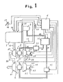
- FIG. 1 shows a drive system having an engine 1 mounted on a motor vehicle (not shown), the engine being a thermally insulated internal combustion engine having at least inner cylinder walls and a cylinder head, piston rings, piston head surfaces, an inner wall of an exhaust passage, and intake and exhaust valves, all made of thermally insulated fine ceramic.
- Air supplied from an air intake passage 11 and fuel injected into the cylinders are mixed into an air-fuel mixture which is then combusted to produce energy to drive the motor vehicle. Exhaust gases are then discharged from the cylinders through an exhaust passage 12.
- a first turbocharger 2 has an exhaust turbine 21 connected to the exhaust passage 12 and a compressor 22 connected to the air intake passage 11.
- the compressor 22 is directly coupled to the rotatable shaft of the exhaust turbine 21.
- the compressor 22 When the exhaust turbine 21 is rotated by the exhaust gases discharged by the exhaust passage 12, the compressor 22 is also rotated and compresses intake air which is fed through the air intake passage 11 to supercharge the engine 1.
- the compressor 22 is coupled to an intake pipe 23 having a valve 24 disposed therein.
- the intake pipe 23 defines an air passage which is selectively opened and closed by the valve 24 that is controlled by a valve actuator 25.
- a rotary electric machine 3 is mounted on the rotatable shaft by which the exhaust turbine 21 and the compressor 22 are directly connected to each other. When electric energy is supplied to the rotary electric machine 3, it operates as an electric motor to rotate the compressor 22 for assisting in rotating the compressor 22 to supercharge the engine 1. When the rotary electric machine 3 is rotated by the exhaust turbine 21, it operates as an electric generator to generate electric power.
- a rotational speed sensor 31 detects the rotational speed of the rotary electric machine 3, i.e., the rotational speed of the first turbocharger 2, and transmits a rotational speed signal to a controller 6 (described later on).
- a second turbocharger 4 has an exhaust turbine 41 connected to an exhaust passage 26 of the first turbocharger 2 and a compressor 42 connected to the compressor 22 of the first turbocharger 2 through an air feed pipe 46.
- the compressor 42 is directly coupled to the rotatable shaft of the exhaust turbine 41.
- the compressor 42 When the exhaust turbine 41 is rotated by the exhaust gases discharged from the first turbocharger 2 through the exhaust passage 26, the compressor 42 is also rotated and compresses intake air to increase the intake air pressure developed by the compressor 22 through the air feed pipe 46.
- the compressor 42 is coupled to an intake pipe 43 having a valve 44 disposed therein.
- the intake pipe 43 defines an air passage which is selectively opened and closed by the valve 44 that is controlled by a valve actuator 45. Control signals are supplied from the controller 6 to the valve actuators 25, 45.
- a rotary electric machine 5 is mounted on the rotatable shaft by which the exhaust turbine 41 and the compressor 42 are directly connected to each other. When electric energy is supplied to the rotary electric machine 5, it operates as an electric motor to rotate the compressor 42 for assisting in rotating the compressor 42 to supercharge the engine 1. When the rotary electric machine 5 is rotated by the exhaust turbine 41, it operates as an electric generator to generate electric power.
- a rotational speed sensor 51 detects the rotational speed of the rotary electric machine 5, i.e., the rotational speed of the second turbocharger 5, and transmits a rotational speed signal to the controller 6.
- a boost pressure sensor 13 is mounted in the intake passages 11 for detecting the boost pressure of intake air to be supplied to the engine 1.
- a load sensor 14 is mounted on the engine 1 for detecting the rate of flow of fuel supplied to the engine 1 thereby to detect the load acting on the engine 1. Detected signals from the sensors 13, 14 are also sent to the controller 6.
- a rotary electric machine 7 is coupled to the rotatable shaft of the engine 1 through a gear train.
- the rotary electric machine 7 When the rotary electric machine 7 is driven by the engine 1, it operates as an electric generator.
- electric energy is supplied to the rotary electric machine 7 from a dual electric power converter 71, it operates as an electric motor.
- the dual electric power converter device 71 has one three-phase AC terminal and two DC terminals. These two DC terminals are connected parallel to each other in the dual electric power converter device 71, and are coupled to DC terminals of a bidirectional AC/DC converter unit in the dual electric power converter device 71.
- the bidirectional AC/DC converter unit comprises an inverter and a converter which are connected parallel to each other. For converting electric energy from DC to AC, the inverter is operated, and for converting electric energy from AC to DC, the converter is operated.
- the bidirectional AC/DC converter unit will not be described in greater detail as it is a known circuit disclosed in detail in Thyristor Phase-Controlled Converters , pages 111 through 144, written by B. R. Pelly and published by WILLY-INTERSCIENCE.
- a control signal for switching the operation of the bidirectional AC/DC converter unit is supplied from the controller 6.
- Dual converter units 73, 75 each comprise a bidirectional AC/DC converter unit which is identical to the bidirectional AC/DC converter unit as described above.
- the dual converter unit 73 has a DC terminal connected to one of the DC terminals of the dual electric power converter device 71, and an AC terminal connected to the rotary electric machine 3.
- the dual converter unit 75 has a DC terminal connected to the other DC terminal of the dual electric power converter device 71, and an AC terminal connected to the rotary electric machine 5.
- the rotational speed of the engine 1 is detected by an engine rotational speed sensor 15 which applies a detected signal to the controller 6.
- An accelerator pedal movement sensor 16 detects the amount of depression of an accelerator pedal 17 which controls the output power of the engine 1. A detected signal from the accelerator pedal movement sensor 16 is sent to the controller 6.
- the controller 6 comprises a microcomputer and has a central processing unit for effecting various arithmetic operations, memories for storing a processing or control sequence, and input/output ports.
- the controller 6 carries out predetermined arithmetic operations and delivers control signals to the valve actuators 25, 45, the dual electric power converter device 71, and the dual converter units 73, 75 according to the stored control sequence.
- the first and second turbochargers 2, 4 are operated by the energy of the exhaust gases.
- the valve 24 associated with the first turbocharger 2 is opened, and the valve 44 associated with the second turbocharger 4 is closed.
- the engine 1 is supercharged by the compressor 22 of the first turbocharger 2.
- the rotary electric machine 3 is operated as a generator, and electric power generated by the rotary electric machine 3 is supplied through the dual converter unit 73 and the dual electric power converter device 71 to the rotary electric machine 7 to rotate the latter for assisting in rotating the rotatable shaft of the engine 1, so that the exhaust gas energy is fed back to the engine 1.
- the controller 6 calculates a power supply frequency for rotating the rotary electric machine 7 at a speed higher than the engine 1, based on the output signal from the engine rotational speed sensor 15. The controller 6 then controls the output frequency of the inverter of the dual electric power converter 71 based on the calculated power supply frequency, while operating the rotary electric machine 7 as a motor.
- the rotary electric machine 5 combined with the second turbocharger 4 is also operated as a generator, and electric power generated by the rotary electric machine 5 is supplied through the dual converter unit 75 and the dual electric power converter device 71 to the rotary electric machine 7.
- the rotary electric machine 7 is therefore driven to assist in rotating the rotatable shaft of the engine 1, so that the exhaust gas energy is fed back to the engine 1.
- the controller 6 controls the output voltage of the converter of the dual converter unit 75 to equalize the DC output voltage of the dual converter unit 75 with the output voltage of the dual converter unit 73.
- the controller 6 also measures the direct currents of the dual converter units 73, 75 with sensors (not shown), and controls the proportion of loads borne by the dual converter units 73, 75.
- valve 24 is closed and the valve 44 is opened.
- the rotary electric machines 3, 5 combined with the first and second turbochargers 2, 4 are operated as motors to assist in rotating the compressors 22, 42 for supercharging the engine 1, thereby increasing the torque produced by the engine 1.
- the electric power which drives the rotary electric machines 3, 5 at this time is generated by the rotary electric machine 7.
- the electric power generated by the rotary electric machine 7 is converted by the dual electric power converter 71 to DC electric power that is supplied to the dual converter units 73, 75.
- the controller 6 calculates power supply frequencies at which the rotary electric machines 3, 5 can be operated as motors, based on the output signals from the rotational speed sensors 31, 51.
- the controller 6 then controls the output frequencies of the inverters of the dual converter units 73, 75 based on the calculated power supply frequencies.
- the DC electric power supplied to the dual converter units 73, 75 is then converted to three-phase AC electric power having the above output frequencies.
- the three-phase AC electric power is then supplied to the rotary electric machines 3, 5 to operate them as motors.
- Figs. 2A and 2B are a flowchart showing an operation sequence to be executed by the controller 6.
- the rotational speed signal from the engine rotational speed sensor 15 is read in a step 1.
- the accelerator pedal depression signal from the accelerator pedal movement sensor 16 is read in a step 2.
- step 3 the controller 6 then determines, based on the detected signals read in the steps 1, 2, whether the engine 1 rotates at a low speed and undergoes a high load and the drive system is to be controlled in a two-stage supercharging mode to increase the pressure of intake air, or not. If the intake air pressure is to be increased, control proceeds to a step 5, and if not, control goes to a step 4.
- the drive system is controlled in a general mode in which the rotary electric machines 3, 5 are not operated as motors.
- the controller 6 calculates the amounts of electric power to be supplied from the rotary electric machine 7 operating as a generator to the rotary electric machines 3, 5.
- the controller 6 applies a signal to the dual electric power converter device 71 to control the output electric power from the dual electric power converter device 71 based on the calculated amounts of electric power in a step 6.
- the controller 6 applies a signal to the valve actuator 25 to close the valve 24 disposed in the intake pipe 23 of the first turbocharger 2.
- the controller 6 applies a signal to the valve actuator 45 to open the valve 44 disposed in the intake pipe 43 of the second turbocharger 4.
- the rotational speed NT1 of the first turbocharger 2 is detected by the rotational speed sensor 31 and sent to the controller 6 in a step 9.
- the controller 6 applies a signal to the dual converter unit 73 to convert the output electric power from the dual electric power converter device 71 to three-phase electric power having such a frequency as to rotate the rotary electric machine 3 at a speed higher than the rotational speed NT1 detected in the step 9.
- the converted electric power is supplied from the dual converter unit 73 to the rotary electric machine 3 to drive the latter as a motor.
- the rotational speed N′T1 of the first turbocharger 2 is detected again by the rotational speed sensor 31, and is compared with the rotational speed NT1 to determine whether the rotational speed of the first turbocharger 2 has increased or not in a step 11. If not increased, control goes to a step 12, and if increased, control proceeds to a step 13.
- the controller 6 diagnoses the drive system for a fault in a predetermined fault diagnosis mode.
- the controller 6 reads the detected signal PCB1 from the boost pressure sensor 13.
- the controller 6 calculates in a step 14 a fuel flow rate QA corresponding to the detected signal PCB1 read in the step 13.
- the controller 6 calculates a fuel injection timing based on the rotational speed signal and the accelerator pedal depression signal read in the steps 1, 2, respectively.
- the controller 6 supplies fuel at the calculated fuel flow rate QA to the engine 1 at the timing calculated in the step 15.
- the controller 6 calculates a required boost pressure PCA corresponding to the detected signal read in the step 2.
- the controller 6 compares in a step 18 the detected signal PCB1 read in the step 13 and the required boost pressure PCA calculated in the step 17. If PCA is smaller than PCB1, then control goes to a step 20, and if PCA is larger than PcB1, then control proceeds to a step 19.
- the controller 6 reads the rotational speed NT2 of the second turbocharger 4 from the rotational speed sensor 51.
- the controller 6 applies a signal to the dual electric power converter device 71 to lower the output electric power from the dual electric power converter device 71.
- the controller 6 applies a signal to the dual converter unit 75 to convert the output electric power from the dual electric power converter device 71 to three-phase electric power having such a frequency as to rotate the rotary electric machine 5 at a speed higher than the rotational speed NT2 detected in the step 19.
- the converted electric power is supplied from the dual converter unit 75 to the rotary electric machine 5 to drive the latter as a motor.
- the rotational speed N′T2 of the rotary electric machine 5 is detected again, and compared with the rotational speed NT2 to determine whether the rotational speed of the second turbocharger 4 has increased or not in a step 22. If not increased, control goes to a step 23, and if increased, control proceeds to a step 24.
- the controller 6 diagnoses the drive system for a fault in a predetermined fault diagnosis mode.
- the controller 6 reads again the detected signal PCB2 from the boost pressure sensor 13.
- the controller 6 calculates in a step 25 a fuel flow rate QB2 corresponding to the detected signal PCB2 read in the step 24.
- a next step 26 the controller 6 calculates again a fuel injection timing based on the rotational speed signal and the accelerator pedal depression signal read in the steps 1, 2, respectively.
- the controller 6 supplies fuel at the calculated fuel flow rate QB2 to the engine 1 at the timing calculated in the step 26.
- a step 28 then compares the fuel flow rate QA calculated in the step 14 and the fuel flow rate QB2 calculated in the step 25. If the fuel flow rate QB2 is greater than the fuel flow rate QA, then control goes to the step 20, and if the fuel flow rate QA is greater than the fuel flow rate QB2, then control goes to a step 29.
- the controller 6 applies a signal to the dual electric power converter device 71 to increase the output electric power therefrom.
- the turbochargers 2, 4 are in a two-stage configuration to reduce their respective moments of inertia for thereby improving their response to the supply of electric power from the dual converter units 73, 75.
- the turbochargers 2, 4 When the turbochargers 2, 4 are started, they can be supplied with large instantaneous electric power so that their initial rotational speeds can be increased rapidly.
- Fig. 3 shows a high-electric-power generator circuit in each of the dual converter units 73, 75.
- the high-electric-power generator circuit includes a capacitor 80 connected through a two-contact switch 81 between DC terminals.
- the two-contact switch 81 has a terminal 81a connected to the negative DC terminal and a terminal 81b connected to the positive DC terminal.
- One terminal of the capacitor 80 is selectively connected to one of the terminals 81a, 81b.
- a diode 82 is coupled between the other terminal of the capacitor 80 and the terminal 81b.
- the two-contact switch 81 is shifted to the terminal 81a and the capacitor 80 is charged.
- the two-contact switch 81 is shifted to the terminal 81b.
- the voltage between the DC terminals is increased by the voltage across the capacitor 80.
- a voltage which is about twice the normal voltage is instantaneously applied to the inverter to increase the output from the inverter. Therefore, the rotational speed of the rotary electric machine 3 or 5 connected to the inverter is rapidly increased.
- the internal resistance of the dual electric power converter device 71 which supplies electric power is large, the internal resistance at the time of starting the rotary electric machine can be reduced by adding a capacitor between the output terminals of the dual electric power converter device 71.
- the rotary electric machine coupled to the engine is operated as a generator to supply electric power to the motor-generators which are operated as motors when the engine rotates at a low speed and undergoes a high load. Since no electric power is supplied from a battery, the electric power supplied to the motor-generators can be supplied stably over a long period of time.
- the engine combined with the turbocharger drive system of the invention can produce an increased torque due to the two-stage turbochargers driven by the motor-generators while the engine is rotating at a low speed. Consequently, the number of gear positions provided by a transmission can be reduced, a condition which has not been possible with a conventional single-stage turbocharger which is driven by only an exhaust turbine, so that the weight and cost of the motor vehicle can be lowered.
Landscapes
- Engineering & Computer Science (AREA)
- Chemical & Material Sciences (AREA)
- Combustion & Propulsion (AREA)
- Mechanical Engineering (AREA)
- General Engineering & Computer Science (AREA)
- Supercharger (AREA)
Claims (6)
- Ein Turboladerantriebssystem für einen Motor (1) mit geschlossenem Brennraum mit
Mitteln (16) zur Feststellung der Motorlast;
Mitteln (15) zur Feststellung der Drehgeschwindigkeit des Motors;
Mitteln (13) zur Feststellung des Ladedrucks des Gases, das an den Motor geliefert wird;
Mitteln (6) zur Speicherung eines gewünschten Ladedrucks gemäß einer festgestellten Motorlast;
einer Vielzahl von Turboladern (2,4);
einer Vielzahl von rotierenden elektrischen Maschinen (3,5), die jeweils auf rotierenden Wellen der Turbolader angebracht sind; und
Mitteln (6) zur Berechnung des Unterschiedes zwischen dem Ladedruck gemäß der festgestellten Last und dem festgestellten Ladedruck; gekennzeichnet durch
die Turbolader (2,4), die jeweils in Serie miteinander verbundene Abgasturbinen (21,41) und Kompressoren (22,42) aufweisen;
eine einzige rotierende elektrische Maschine (7), die von einer Ausgangswelle des Motors antreibbar ist;
Mittel (6) zum Antrieb der einzigen rotierenden elektrischen Maschine als ein elektrischer Generator;
Mittel (6,73) zum Antrieb der Mehrzahl der rotierenden elektrischen Maschinen (3,5) als elektrische Motoren nacheinander durch die rotierende elektrische Maschine an dem Turbolader (2), der sich dem Motor am nächsten befindet, wenn die Ladedruckdifferenz ansteigt, wenn der festgestellte Ladedruck kleiner ist als der Ladedruck gemäß der festgestellten Last; und
Mittel (6,71,73) für die Zufuhr elektrischer Energie von der von dem Motor angetriebenen elektrischen Maschine (7), wenn sie als Generator arbeitet, zu der Vielzahl von rotierenden elektrischen Maschinen (3,5), wenn sie als Motoren arbeiten. - Ein Antriebssystem nach Anspruch 1, bei dem die rotierende elektrische Maschine (7), die durch den Motor angetrieben wird, einen elektrischen Wechselstromgenerator umfaßt, die Mittel für die Zufuhr elektrischer Energie einen Konverter (71) zum Gleichrichten des elektrischen Wechselstromes in elektrischen Glelchstrom, der durch den elektrischen Wechselstromgenerator erzeugt worden ist, und einen Inverter (73,75) zur Umwandlung des elektrischen Gleichstromes in elektrischen Wechselstrom mit einer vorgegebenen Frequenz zur Zufuhr des elektrischen Wechselstromes zu den Motoren umfassen.
- Ein Antriebssystem nach Anspruch 2, bei dem die Mittel (6,73) zum Antrieb der Mehrzahl von rotierenden elektrischen Maschinen Mittel (80,81,82) zur Erhöhung der elektrischen Energie aufweisen, die zu der Mehrzahl von rotierenden elektrischen Maschinen (3,5) geliefert wird, wenn letztere im Begriff sind, angetrieben zu werden.
- Ein Antriebssystem nach einem der Ansprüche 1 bis 3, das außerdem Lufteinlaßpassagen (23,43) einschließt, die an die jeweiligen Kompressoren der Turbolader (2,4) angeschlossen sind, sowie Mittel (6,24,25,44,45) für die nacheinander erfolgende Öffnung der Lufteinlaßpassagen.
- Ein Antriebssystem nach einem der Ansprüche 1 bis 4, bei dem der Motor (1) mit geschlossenem Brennraum einen thermisch isolierten Motor umfaßt, bei dem mindestens die inneren Wände der Brennräume aus einem thermisch isolierenden Keramikwerkstoff bestehen.
- Ein Antriebssystem nach einem der Ansprüche 1 bis 5, bei dem die rotierenden elektrischen Maschinen (3,5) an den Turboladerwellen durch die Turbolader (2,4) angetrieben werden können, und die rotierende elektrische Maschine (7), die mit dem Motor verbunden ist, an eine Ausgangswelle des Motors angeschlossen werden kann, wobei Mittel (6,71,73) vorgesehen sind, um die rotierenden elektrischen Turboladermaschinen als elektrische Generatoren anzutreiben, um die an dem Motor angebrachte rotierende elektrische Maschine als einen Elektromotor anzutreiben, und um elektrische Energie von den elektrischen Generatoren zu dem Motor zu liefern.
Applications Claiming Priority (2)
| Application Number | Priority Date | Filing Date | Title |
|---|---|---|---|
| JP63178722A JP2526100B2 (ja) | 1988-07-18 | 1988-07-18 | 過給機の制御装置 |
| JP178722/88 | 1988-07-18 |
Publications (2)
| Publication Number | Publication Date |
|---|---|
| EP0352064A1 EP0352064A1 (de) | 1990-01-24 |
| EP0352064B1 true EP0352064B1 (de) | 1992-09-09 |
Family
ID=16053428
Family Applications (1)
| Application Number | Title | Priority Date | Filing Date |
|---|---|---|---|
| EP89307257A Expired - Lifetime EP0352064B1 (de) | 1988-07-18 | 1989-07-18 | Antriebssystem für Turbolader mit umlaufenden Elektromaschinen |
Country Status (4)
| Country | Link |
|---|---|
| US (2) | US4958497A (de) |
| EP (1) | EP0352064B1 (de) |
| JP (1) | JP2526100B2 (de) |
| DE (1) | DE68902799T2 (de) |
Families Citing this family (105)
| Publication number | Priority date | Publication date | Assignee | Title |
|---|---|---|---|---|
| JP3023510B2 (ja) * | 1989-12-12 | 2000-03-21 | 株式会社いすゞセラミックス研究所 | フライホイール発電機付きエンジン |
| SE467634B (sv) * | 1990-05-15 | 1992-08-17 | Volvo Ab | Anordning vid turboreglering |
| JPH0776533B2 (ja) * | 1991-07-06 | 1995-08-16 | いすゞ自動車株式会社 | 回転電機付ターボチャージャの駆動装置 |
| US5391925A (en) * | 1993-09-10 | 1995-02-21 | Trigen Energy Corporation | Prime mover driven compressor/chiller with motor on common shaft for large cooling systems |
| JPH08121183A (ja) * | 1994-10-27 | 1996-05-14 | Isuzu Motors Ltd | 電動・発電機付ターボチャージャの制御システム |
| DE19518317C2 (de) * | 1995-05-18 | 2000-01-20 | Gerhard Huber | Vorrichtung und Verfahren zum Betrieb eines elektrisch unterstützten Turboladers |
| US6256993B1 (en) | 1995-07-28 | 2001-07-10 | Honeywell International, Inc. | Motor-assisted variable geometry turbocharging system |
| US5560208A (en) * | 1995-07-28 | 1996-10-01 | Halimi; Edward M. | Motor-assisted variable geometry turbocharging system |
| EP0755816A3 (de) * | 1995-07-28 | 1998-09-02 | Isuzu Ceramics Research Institute Co., Ltd. | Hybrides Elektrofahrzeug |
| KR19990067128A (ko) * | 1995-10-27 | 1999-08-16 | 윌리암 이.울렌웨버 | 2 사이클 내연기관용 과급기 시스템 |
| US6029452A (en) | 1995-11-15 | 2000-02-29 | Turbodyne Systems, Inc. | Charge air systems for four-cycle internal combustion engines |
| US5808460A (en) * | 1997-09-29 | 1998-09-15 | Texas Instruments Incorporated | Rapid power enabling circuit |
| US6032466A (en) * | 1996-07-16 | 2000-03-07 | Turbodyne Systems, Inc. | Motor-assisted turbochargers for internal combustion engines |
| US5870894A (en) * | 1996-07-16 | 1999-02-16 | Turbodyne Systems, Inc. | Motor-assisted supercharging devices for internal combustion engines |
| US5906098A (en) * | 1996-07-16 | 1999-05-25 | Turbodyne Systems, Inc. | Motor-generator assisted turbocharging systems for use with internal combustion engines and control method therefor |
| US5787711A (en) * | 1996-09-16 | 1998-08-04 | Turbodyne Systems, Inc. | Motor-assisted turbo-cooling system for internal combustion engines |
| US5904471A (en) * | 1996-12-20 | 1999-05-18 | Turbodyne Systems, Inc. | Cooling means for a motor-driven centrifugal air compressor |
| US5857332A (en) * | 1996-12-20 | 1999-01-12 | Turbodyne Systems, Inc. | Bearing systems for motor-assisted turbochargers for internal combustion engines |
| US5867987A (en) * | 1997-02-25 | 1999-02-09 | Turbodyne Systems, Inc. | Method and apparatus for combined improved engine operation, warm-up and braking |
| US6085527A (en) * | 1997-05-15 | 2000-07-11 | Turbodyne Systems, Inc. | Magnet assemblies for motor-assisted turbochargers |
| US6062026A (en) * | 1997-05-30 | 2000-05-16 | Turbodyne Systems, Inc. | Turbocharging systems for internal combustion engines |
| US5927075A (en) * | 1997-06-06 | 1999-07-27 | Turbodyne Systems, Inc. | Method and apparatus for exhaust gas recirculation control and power augmentation in an internal combustion engine |
| US6135731A (en) * | 1997-06-26 | 2000-10-24 | Turbodyne Systems, Inc. | Compact and self-cooling blower assembly |
| US6079211A (en) * | 1997-08-14 | 2000-06-27 | Turbodyne Systems, Inc. | Two-stage supercharging systems for internal combustion engines |
| US6138649A (en) * | 1997-09-22 | 2000-10-31 | Southwest Research Institute | Fast acting exhaust gas recirculation system |
| US6145314A (en) * | 1998-09-14 | 2000-11-14 | Turbodyne Systems, Inc. | Compressor wheels and magnet assemblies for internal combustion engine supercharging devices |
| US6408625B1 (en) | 1999-01-21 | 2002-06-25 | Cummins Engine Company, Inc. | Operating techniques for internal combustion engines |
| US6324846B1 (en) * | 1999-03-31 | 2001-12-04 | Caterpillar Inc. | Exhaust gas recirculation system for an internal combustion engine |
| DE19956526C1 (de) * | 1999-11-24 | 2001-04-26 | Gruendl & Hoffmann Gmbh Ges Fu | Antriebsaggregat für ein Kraftfahrzeug mit einem mit einer elektrischen Maschine gekoppelten Hubkolben-Verbrennungsmotor |
| US6357234B1 (en) * | 2000-09-21 | 2002-03-19 | Caterpillar Inc. | Turbocharger system with turbines having independently controlled variable nozzles |
| DE10063321A1 (de) | 2000-12-19 | 2002-06-20 | Gfas Mbh Ges Fuer Aufladetechn | Elektrisch angetriebener Strömungsverdichter |
| GB2375834B (en) | 2001-02-22 | 2005-06-15 | Cummins Engine Co Inc | Regulating speed of an internal combustion engine |
| DE10136977A1 (de) * | 2001-07-28 | 2003-02-06 | Bosch Gmbh Robert | Verfahren und Vorrichtung zum Betreiben eines elektrischen Laders |
| EP1300570B1 (de) * | 2001-10-03 | 2005-05-25 | Visteon Global Technologies, Inc. | Steuerung für eine aufgeladene Brennkraftmaschine mit elektronisch geregeltem Ansaugluftverdichter |
| US6553764B1 (en) * | 2001-12-19 | 2003-04-29 | Caterpillar Inc | Enhanced response turbocharger using flywheel storage |
| DE10209002A1 (de) * | 2002-02-28 | 2003-09-11 | Daimler Chrysler Ag | 2-stufige Aufladung am V-Motor |
| JP2004092634A (ja) * | 2002-07-12 | 2004-03-25 | Kokusan Denki Co Ltd | 発電機搭載内燃機関駆動車両 |
| US6647724B1 (en) * | 2002-07-30 | 2003-11-18 | Honeywell International Inc. | Electric boost and/or generator |
| ITCE20020009A1 (it) * | 2002-09-30 | 2002-12-30 | Giuseppe Ferraro | Dispositivo a girante palettata reversibile con motore/generatore elettrico "senza spazzole" per la gestione dell'aria di sovralimentazione |
| FR2852356B1 (fr) * | 2003-03-13 | 2005-04-29 | Moteur suralimente a turbocompresseur electriquement assiste | |
| DE602004010439T2 (de) * | 2004-05-07 | 2008-10-23 | Honeywell International Inc. | Verfahren zum betrieb eines elektrisch unterstützten turboladers und verstärkungsvorrichtung |
| EP1619367A1 (de) * | 2004-07-19 | 2006-01-25 | Ford Global Technologies, LLC, A subsidary of Ford Motor Company | Verfahren und Vorrichtung zur Steuerung eines elektrisch angetriebenen Laders in einer Brennkraftmaschine |
| US20080121218A1 (en) * | 2004-12-13 | 2008-05-29 | Caterpillar Inc. | Electric turbocompound control system |
| US7174714B2 (en) * | 2004-12-13 | 2007-02-13 | Caterpillar Inc | Electric turbocompound control system |
| US20060162334A1 (en) * | 2005-01-25 | 2006-07-27 | Mr. Kyle Roesler | Turbo-Hybrid Automobile |
| US7047743B1 (en) * | 2005-03-14 | 2006-05-23 | Deere & Company | Electric turbo compound configuration for an engine/electric generator system |
| US7076954B1 (en) | 2005-03-31 | 2006-07-18 | Caterpillar Inc. | Turbocharger system |
| US20070144175A1 (en) * | 2005-03-31 | 2007-06-28 | Sopko Thomas M Jr | Turbocharger system |
| US7571608B2 (en) * | 2005-11-28 | 2009-08-11 | General Electric Company | Turbocharged engine system and method of operation |
| US20070137197A1 (en) * | 2005-12-21 | 2007-06-21 | David Turner | Engine supercharging system |
| US7541687B2 (en) * | 2006-03-10 | 2009-06-02 | Deere & Company | Method and system for managing an electrical output of a turbogenerator |
| JP4067025B2 (ja) * | 2006-09-11 | 2008-03-26 | いすゞ自動車株式会社 | 多段ターボチャージャの制御装置 |
| US20080087482A1 (en) * | 2006-10-13 | 2008-04-17 | Ford Global Technologies, Llc | Hybrid electric vehicle with motor driven charge air booster |
| WO2008075130A1 (en) * | 2006-12-19 | 2008-06-26 | Renault Trucks | Power unit for an automotive vehicle and vehicle including such a power unit |
| DE602006018806D1 (de) * | 2006-12-19 | 2011-01-20 | Renault Trucks | Antriebsaggregat für ein kraftfahrzeug und fahrzeug mit solch einem antriebsaggregat |
| DE102007017777B4 (de) * | 2007-04-16 | 2009-04-09 | Siemens Ag | Turboladeranordnung und turboaufladbare Brennkraftmaschine |
| US7891185B2 (en) * | 2007-08-17 | 2011-02-22 | Deere & Company | Turbo-generator control with variable valve actuation |
| US7921944B2 (en) * | 2007-10-29 | 2011-04-12 | Ford Global Technologies, Llc | Compression system for internal combustion engine including a rotationally uncoupled exhaust gas turbine |
| DE102008003333A1 (de) | 2008-01-07 | 2009-07-09 | Dirk Landau | Brennkraftmaschine zur Erzeugung von Wärme und elektrischer Energie, ausgeführt als stromerzeugende Heizung |
| US20090205331A1 (en) * | 2008-02-19 | 2009-08-20 | Marsh J Kendall | Piston based double compounding engine |
| JP4875654B2 (ja) * | 2008-04-11 | 2012-02-15 | 三菱重工業株式会社 | 過給装置 |
| US8061137B2 (en) * | 2008-05-30 | 2011-11-22 | Caterpillar Inc. | Fuel control system for limiting turbocharger speed |
| CN102165158B (zh) * | 2008-09-26 | 2013-09-25 | 雷诺卡车公司 | 尤其用于机动车辆的动力总成 |
| JP5331435B2 (ja) * | 2008-10-07 | 2013-10-30 | ヤンマー株式会社 | エンジン |
| JP5335358B2 (ja) * | 2008-10-07 | 2013-11-06 | ヤンマー株式会社 | エンジン |
| US8143732B2 (en) * | 2008-12-15 | 2012-03-27 | Caterpillar Inc. | Stationary genset power system having turbo-compounding |
| CN102272426B (zh) * | 2009-03-06 | 2013-07-24 | 丰田自动车株式会社 | 多级增压系统控制装置 |
| US8253260B2 (en) * | 2009-07-23 | 2012-08-28 | Navistar Canada, Inc. | Exhaust turbine generator system and method of controlling the same |
| DE102009034510A1 (de) | 2009-07-24 | 2011-04-14 | Bayerische Motoren Werke Aktiengesellschaft | Fahrzeug mit aufgeladenem Verbrennungsmotor sowie Verfahren zum Betreiben eines Fahrzeugs mit aufgeladenem Verbrennungsmotor |
| US20110022289A1 (en) * | 2009-07-27 | 2011-01-27 | Ecomotors International, Inc. | Method of controlling an electrically assisted turbocharger |
| US8958971B2 (en) | 2009-07-27 | 2015-02-17 | Ecomotors, Inc. | System and method to control an electronically-controlled turbocharger |
| DE102010032249A1 (de) * | 2009-08-06 | 2011-02-10 | Schaeffler Technologies Gmbh & Co. Kg | Turbolader einer Brennkraftmaschine |
| DE102009046076A1 (de) * | 2009-10-28 | 2011-05-12 | Robert Bosch Gmbh | Generatoreinheit, insbesondere für Kraftfahrzeuge |
| JP2011163201A (ja) * | 2010-02-09 | 2011-08-25 | Komatsu Ltd | エンジン |
| JP5330296B2 (ja) * | 2010-03-12 | 2013-10-30 | 三菱電機株式会社 | 電動過給機 |
| JP5700237B2 (ja) * | 2010-07-08 | 2015-04-15 | 株式会社Ihi | 排熱回収装置 |
| IT1401426B1 (it) * | 2010-08-11 | 2013-07-26 | Nuova Pignone S R L | Metodi e dispositivi usati per controllare automaticamente la velocita di un espansore |
| IT1401427B1 (it) | 2010-08-11 | 2013-07-26 | Nuova Pignone S R L | Metodi e dispositivi usati per controllare automaticamente la velocita di un espansore |
| JP5678580B2 (ja) * | 2010-10-28 | 2015-03-04 | いすゞ自動車株式会社 | 内燃機関の制御装置 |
| JP5874161B2 (ja) * | 2010-10-28 | 2016-03-02 | いすゞ自動車株式会社 | ターボ過給システム |
| JP2012092792A (ja) * | 2010-10-28 | 2012-05-17 | Isuzu Motors Ltd | 内燃機関の制御装置 |
| JP2012097606A (ja) * | 2010-10-29 | 2012-05-24 | Isuzu Motors Ltd | ターボ過給システム |
| US8943823B2 (en) * | 2010-11-18 | 2015-02-03 | Caterpillar Inc. | Fluid handling system having dedicated EGR turbo-generator |
| EP2463496A1 (de) | 2010-12-10 | 2012-06-13 | Perkins Engines Company Limited | Mehrfache Turboladersteuerung |
| CN102155290B (zh) * | 2011-03-20 | 2012-07-11 | 北京理工大学 | 一种用于恢复内燃机高原动力的燃机型辅助增压系统 |
| RU2600839C2 (ru) * | 2011-05-30 | 2016-10-27 | Фпт Моторенфоршунг Аг | Гибридная турбокомпаундная двигательная установка с наддувом |
| DE102012019967B4 (de) * | 2012-10-08 | 2014-04-24 | Iav Gmbh Ingenieurgesellschaft Auto Und Verkehr | Aufladeeinrichtung für Brennkraftmaschinen |
| US9151217B2 (en) * | 2012-12-21 | 2015-10-06 | Ford Global Technologies, Llc | Twin turbocharger wastegate control |
| US9010114B2 (en) * | 2013-02-19 | 2015-04-21 | The Boeing Company | Air charge system and method for an internal combustion engine |
| CN103615306A (zh) * | 2013-11-29 | 2014-03-05 | 东风小康汽车有限公司重庆分公司 | 涡轮增压装置 |
| ES2597163T3 (es) * | 2013-12-20 | 2017-01-16 | Fpt Motorenforschung Ag | Esquema de turbotracción mejorado, en particular en el campo de los vehículos industriales |
| US9166510B1 (en) * | 2014-04-02 | 2015-10-20 | Hamilton Sundstrand Corporation | Systems utilizing a controllable voltage AC generator system |
| EP3155246A4 (de) | 2014-06-15 | 2018-02-28 | BorgWarner Inc. | System und verfahren zur steuerung eines elektronisch gesteuerten turboladers während eines autoshift-ereignisses des getriebes |
| FR3025833B1 (fr) * | 2014-09-15 | 2017-12-29 | Renault Sas | Groupe motopropulseur equipe d'un compresseur electrique et procede de pilotage de ce groupe motopropulseur |
| DE102014221333B4 (de) * | 2014-10-21 | 2022-07-07 | Ford Global Technologies, Llc | Zwillingsturbo-System mit elektrisch antreibbaren Verdichtern |
| US20160138463A1 (en) * | 2014-11-17 | 2016-05-19 | Arnold Magnetic Technologies | System and method for providing multiple voltage buses on a single vehicle |
| GB2535617B (en) * | 2015-01-05 | 2020-08-12 | Borgwarner Inc | Electrically driven compressor-expander for a turbocharged engine system and associated flow control valves |
| US11105258B2 (en) | 2015-02-03 | 2021-08-31 | Williams International Co., L.L.C. | Turbo-electric turbo-compounding system |
| US11105259B2 (en) | 2015-02-03 | 2021-08-31 | Williams International Co., L.L.C. | Turbo-electric turbo-compounding method |
| DE102015001662A1 (de) * | 2015-02-10 | 2016-08-11 | Man Diesel & Turbo Se | Brennkraftmaschine, Verfahren zum Betreiben derselben und Steuerungseinrichtung zur Duchführung des Verfahrens |
| GB2540446B (en) | 2016-01-07 | 2018-12-12 | Ford Global Tech Llc | Method and system to deliver smooth engine torque |
| DE102016203823B3 (de) * | 2016-03-09 | 2017-08-24 | Ford Global Technologies, Llc | Verfahren zum Betreiben einer abgasturboaufgeladenen Brennkraftmaschine mit Teilabschaltung |
| DE112017002878T5 (de) * | 2016-06-08 | 2019-02-21 | Jaguar Land Rover Limited | Verbrennungsmotoransaugsystem und -Ventilbaugruppe |
| GB2551161B (en) * | 2016-06-08 | 2020-03-18 | Jaguar Land Rover Ltd | Internal combustion engine intake system with configurable electric superchargers |
| CN111350583A (zh) * | 2018-12-21 | 2020-06-30 | 博格华纳公司 | 用于内燃机的涡轮增压器 |
Citations (2)
| Publication number | Priority date | Publication date | Assignee | Title |
|---|---|---|---|---|
| EP0345991A1 (de) * | 1988-06-10 | 1989-12-13 | Isuzu Motors Limited | Antriebssystem für Turbolader mit drehender elektrischer Maschine |
| EP0349151A1 (de) * | 1988-06-29 | 1990-01-03 | Isuzu Motors Limited | Antriebssystem für Turbolader mit elektrischer Rotationsmaschine |
Family Cites Families (14)
| Publication number | Priority date | Publication date | Assignee | Title |
|---|---|---|---|---|
| US2503289A (en) * | 1948-04-05 | 1950-04-11 | Supercharged internal-combustion | |
| GB1062983A (en) * | 1962-12-21 | 1967-03-22 | Perkins Engines Ltd | Pressure charging system for internal combustion engines |
| FR2183337A5 (de) * | 1972-05-03 | 1973-12-14 | Breting Olivier | |
| DE2609389A1 (de) * | 1976-03-06 | 1977-09-08 | Maschf Augsburg Nuernberg Ag | Abgasturboladeraggregat |
| JPS6043152A (ja) * | 1983-08-20 | 1985-03-07 | Isuzu Motors Ltd | 断熱エンジンのライナ−ヘツドおよびシリンダライナ− |
| JPS60195329A (ja) * | 1984-03-17 | 1985-10-03 | Isuzu Motors Ltd | 内燃機関のタ−ボチヤ−ジヤ |
| DE3437872C1 (de) * | 1984-10-16 | 1986-05-28 | M.A.N.-B & W Diesel GmbH, 8900 Augsburg | Steuereinrichtung fuer einen Verbrennungsmotor mit einem Abgasturbolader |
| JPS6226334A (ja) * | 1985-07-26 | 1987-02-04 | Isuzu Motors Ltd | タ−ボチヤ−ジヤの制御装置 |
| US4798257A (en) * | 1985-10-19 | 1989-01-17 | Isuzu Motors Limited | Energy recovery apparatus for turbo compound engine |
| JPH0647936B2 (ja) * | 1985-10-19 | 1994-06-22 | いすゞ自動車株式会社 | タ−ボコンパウンドエンジン |
| JPS6293429A (ja) * | 1985-10-19 | 1987-04-28 | Isuzu Motors Ltd | タ−ボコンパウンドエンジン |
| JP2510855B2 (ja) * | 1986-02-10 | 1996-06-26 | いすゞ自動車株式会社 | 車両におけるエネルギ−回収装置 |
| JPS63302119A (ja) * | 1987-05-30 | 1988-12-09 | Isuzu Motors Ltd | 排気エネルギ−回収エンジン |
| JP2640757B2 (ja) * | 1988-07-18 | 1997-08-13 | 株式会社いすゞセラミックス研究所 | 過給機の制御装置 |
-
1988
- 1988-07-18 JP JP63178722A patent/JP2526100B2/ja not_active Expired - Lifetime
-
1989
- 1989-07-17 US US07/380,316 patent/US4958497A/en not_active Expired - Fee Related
- 1989-07-18 DE DE8989307257T patent/DE68902799T2/de not_active Expired - Fee Related
- 1989-07-18 EP EP89307257A patent/EP0352064B1/de not_active Expired - Lifetime
-
1990
- 1990-07-12 US US07/551,324 patent/US5105624A/en not_active Expired - Fee Related
Patent Citations (2)
| Publication number | Priority date | Publication date | Assignee | Title |
|---|---|---|---|---|
| EP0345991A1 (de) * | 1988-06-10 | 1989-12-13 | Isuzu Motors Limited | Antriebssystem für Turbolader mit drehender elektrischer Maschine |
| EP0349151A1 (de) * | 1988-06-29 | 1990-01-03 | Isuzu Motors Limited | Antriebssystem für Turbolader mit elektrischer Rotationsmaschine |
Also Published As
| Publication number | Publication date |
|---|---|
| DE68902799T2 (de) | 1993-01-14 |
| JPH0230924A (ja) | 1990-02-01 |
| JP2526100B2 (ja) | 1996-08-21 |
| DE68902799D1 (de) | 1992-10-15 |
| US4958497A (en) | 1990-09-25 |
| EP0352064A1 (de) | 1990-01-24 |
| US5105624A (en) | 1992-04-21 |
Similar Documents
| Publication | Publication Date | Title |
|---|---|---|
| EP0352064B1 (de) | Antriebssystem für Turbolader mit umlaufenden Elektromaschinen | |
| US4955199A (en) | Drive system for turbochargers with rotary electric machines | |
| EP0223419B1 (de) | Energierückgewinnungsvorrichtung für eine aufgeladene Brennkraftmaschine | |
| EP0311457A1 (de) | Kontrollsystem für Turbolader mit drehender elektrischer Maschine | |
| JPH0525008B2 (de) | ||
| JPH03117628A (ja) | 回転電機付ターボチャージャの制御装置 | |
| JPS62111124A (ja) | 過給式の内燃機関 | |
| KR900007790B1 (ko) | 엔진의 에너지 회수장치 | |
| JP2884725B2 (ja) | ツインターボチャージャの制御装置 | |
| JPH03202633A (ja) | 回転電機付ターボチャージャの制御装置 | |
| JPH045804B2 (de) | ||
| JPH08182382A (ja) | 電動・発電機付ターボチャージャの制御装置 | |
| JPH10159576A (ja) | 回転電機付ターボチャージャの制御装置 | |
| JPH04342828A (ja) | 回転電機付ターボチャージャの制御装置 | |
| JPH0275724A (ja) | 過給機の制御装置 | |
| JP3161158B2 (ja) | 回転電機付ターボチャージャ制御装置 | |
| JP3132266B2 (ja) | 排気エネルギー回収装置 | |
| JP2987859B2 (ja) | 回転電機付ターボチャージャの制御装置 | |
| JP2819785B2 (ja) | ターボチャージャの制御装置 | |
| JP3208872B2 (ja) | ターボチャージャ用回転電機の制御装置 | |
| JPH04276134A (ja) | 回転電機付ターボチャージャの制御装置 | |
| JPH07180564A (ja) | エンジンのエネルギ−回収装置 | |
| JPH03145530A (ja) | アイドル時発電量増大装置 | |
| JPH0412130A (ja) | 回転電機付ターボチャージャ | |
| JPH0233413A (ja) | 回転電機付ターボチャージャの駆動装置 |
Legal Events
| Date | Code | Title | Description |
|---|---|---|---|
| PUAI | Public reference made under article 153(3) epc to a published international application that has entered the european phase |
Free format text: ORIGINAL CODE: 0009012 |
|
| AK | Designated contracting states |
Kind code of ref document: A1 Designated state(s): DE FR GB |
|
| 17P | Request for examination filed |
Effective date: 19900319 |
|
| 17Q | First examination report despatched |
Effective date: 19910403 |
|
| GRAA | (expected) grant |
Free format text: ORIGINAL CODE: 0009210 |
|
| AK | Designated contracting states |
Kind code of ref document: B1 Designated state(s): DE FR GB |
|
| REF | Corresponds to: |
Ref document number: 68902799 Country of ref document: DE Date of ref document: 19921015 |
|
| ET | Fr: translation filed | ||
| PLBE | No opposition filed within time limit |
Free format text: ORIGINAL CODE: 0009261 |
|
| STAA | Information on the status of an ep patent application or granted ep patent |
Free format text: STATUS: NO OPPOSITION FILED WITHIN TIME LIMIT |
|
| 26N | No opposition filed | ||
| PGFP | Annual fee paid to national office [announced via postgrant information from national office to epo] |
Ref country code: FR Payment date: 20000711 Year of fee payment: 12 |
|
| PGFP | Annual fee paid to national office [announced via postgrant information from national office to epo] |
Ref country code: GB Payment date: 20000713 Year of fee payment: 12 |
|
| PGFP | Annual fee paid to national office [announced via postgrant information from national office to epo] |
Ref country code: DE Payment date: 20000717 Year of fee payment: 12 |
|
| PG25 | Lapsed in a contracting state [announced via postgrant information from national office to epo] |
Ref country code: GB Free format text: LAPSE BECAUSE OF NON-PAYMENT OF DUE FEES Effective date: 20010718 |
|
| GBPC | Gb: european patent ceased through non-payment of renewal fee |
Effective date: 20010718 |
|
| PG25 | Lapsed in a contracting state [announced via postgrant information from national office to epo] |
Ref country code: FR Free format text: LAPSE BECAUSE OF NON-PAYMENT OF DUE FEES Effective date: 20020329 |
|
| PG25 | Lapsed in a contracting state [announced via postgrant information from national office to epo] |
Ref country code: DE Free format text: LAPSE BECAUSE OF NON-PAYMENT OF DUE FEES Effective date: 20020501 |
|
| REG | Reference to a national code |
Ref country code: FR Ref legal event code: ST |