EP0351514A2 - Guide d'ondes à torsade - Google Patents
Guide d'ondes à torsade Download PDFInfo
- Publication number
- EP0351514A2 EP0351514A2 EP89108556A EP89108556A EP0351514A2 EP 0351514 A2 EP0351514 A2 EP 0351514A2 EP 89108556 A EP89108556 A EP 89108556A EP 89108556 A EP89108556 A EP 89108556A EP 0351514 A2 EP0351514 A2 EP 0351514A2
- Authority
- EP
- European Patent Office
- Prior art keywords
- waveguide
- coupling
- polarization
- window
- coupling window
- Prior art date
- Legal status (The legal status is an assumption and is not a legal conclusion. Google has not performed a legal analysis and makes no representation as to the accuracy of the status listed.)
- Granted
Links
Images


Classifications
-
- H—ELECTRICITY
- H01—ELECTRIC ELEMENTS
- H01P—WAVEGUIDES; RESONATORS, LINES, OR OTHER DEVICES OF THE WAVEGUIDE TYPE
- H01P1/00—Auxiliary devices
- H01P1/16—Auxiliary devices for mode selection, e.g. mode suppression or mode promotion; for mode conversion
- H01P1/161—Auxiliary devices for mode selection, e.g. mode suppression or mode promotion; for mode conversion sustaining two independent orthogonal modes, e.g. orthomode transducer
-
- H—ELECTRICITY
- H01—ELECTRIC ELEMENTS
- H01P—WAVEGUIDES; RESONATORS, LINES, OR OTHER DEVICES OF THE WAVEGUIDE TYPE
- H01P1/00—Auxiliary devices
- H01P1/02—Bends; Corners; Twists
Definitions
- the invention relates to a waveguide twist according to the preamble of claim 1.
- the straight waveguide is the basic element in waveguide technology.
- the corner is chamfered to reduce the adjustment error.
- manifolds are used with a continuous curvature and a constant cross-section.
- the curvature usually 90 °, can be carried out in the direction of the electrical field lines (E-bend), i.e. in the case of the rectangular hollow line over the broad side, or in the direction of the magnetic field lines (H-bend), i.e. in the case of rectangular hollow line in the direction of the narrow side.
- the waveguide provided with a rectangular cross section can also be twisted helically as a whole about its longitudinal axis in order to change the polarization plane by 90 °, as is described, for example, in DE-PS 976 910.
- polarizing switches are known for example from DE 33 45 689 Al, DE 30 10 360 C2 and GB-PS 1 591 719.
- These broadband polarization switches are used to separate orthogonally linearly polarized electromagnetic waves.
- a waveguide section on the input side has a rectangular or square cross-section with two coupling windows lying laterally opposite one another, from which rectangular waveguide arms branch off and open into a common broadband branch with the inclusion of elbows.
- polarization switches are used that are completely implemented in waveguide technology, they are always based on the same principle. They consist of a round or square waveguide to which two or more waveguides are connected. Two main wave types with mutually perpendicular polarization planes can be propagated in the square or round waveguide and are coupled separately from one another into one or more rectangular waveguides assigned only to one polarization.
- This functional principle can be implemented in a simple version with a polarization switch in such a way that square waveguides are provided for the transmission of two waves with polarization planes oriented perpendicular to one another.
- a transverse short circuit is arranged in it and, on the opposite side of the waveguide section with a square cross section, a longitudinal coupling window, that is to say in the propagation direction, in which the electromagnetic wave is coupled out with the polarization plane lying in the plane of the coupling window.
- this electromagnetic wave can only be deflected by 90 ° in such a way that the direction of propagation of the two waves, which are now each separated on a waveguide branch, takes place parallel to one another.
- a corresponding waveguide polarization switch therefore comprises on one connection side the two polarization gates one above the other for the two waveguide branches, in which the two separate electromagnetic waves are transmitted. Even if, by arranging an H-bend after the coupling window, the direction of propagation of the two coupled waves is brought into line and the connections of the two switch outputs can lie in one plane, it remains to be determined that the orientation of the two connecting waveguides is perpendicular to each other. Because of the way of coupling, the two polarizations spread separately in different waveguides in the same direction, but their orientation in space is still perpendicular to each other.
- microwave converters are to be connected downstream, as is required in satellite technology, then these must also be aligned with the polarization lying perpendicular to one another, which is not always desirable from a constructional point of view is when the microwave converters are rectangular in cross-section and thus take up more space.
- a so-called "twist” d h it would also be conceivable for a so-called "twist” d h. So a so-called "waveguide twist" is ordered. However, this would lead to an axial extension of the required installation space, since then, for example, a microwave converter could only be installed offset by the installation length of the so-called "twist".
- the present invention indeed enables the possibility of a rotation of the polarization plane by, for example, 90 ° in an astonishing manner with the smallest installation space. This is made possible by the way in which one waveguide branch is coupled to the other, so that the electromagnetic waves in one polarization plane are coupled into the other waveguide branch by rotating their polarization plane by 90 °.
- the principle according to the invention can be used not only with the shaft types H10 and H01, that is to say with square or rectangular waveguides in cross section, but also with waveguides with round waves in cross section with the shaft types H11 and H11.
- the waveguides can also be provided with discontinuities.
- Fig. 1 is a rectangular first waveguide 1 for example for the transmission of a linearly polarized electromagnetic table wave shown type H10.
- a coupling window 5 is provided, the height of which generally corresponds to the broad side of the waveguide 1. In practice, however, the height of the coupling window 5 will generally be up to approximately 10% less than the broad side of the waveguide 1.
- the narrow side of the coupling window 5 is only half the length of its length.
- an example of the magnetic field line 7 is shown in FIG. 1 in front of the waveguide 1.
- the direction of propagation is changed by 90 ° to the vertical without changing the polarization plane.
- a second waveguide 13 is arranged above the first waveguide 1.
- the second waveguide 13 is parallel to the waveguide 1, in such a way that the two coupling windows 5 lie one on top of the other.
- the coupling window 5 in the second waveguide 13 z3 was also arranged in its longitudinal direction, but off-center to the longitudinal axis.
- the longitudinal or broad sides of the waveguide 13 to the first waveguide 1 are reversed by 90 °, so that in the waveguide 13, for example, an electromagnetic wave of the type H 1 can be excited.
- the electromagnetic field lines 7 shown in FIG. 1 are coupled onto the second waveguide 13 via the coupling window 5 in such a way that magnetic field lines 15 are excited there. This is only achieved by the eccentric arrangement of the coupling window 5 with respect to the second waveguide 13. Because in the coupling window the magnetic field lines are rectified, so that an electromagnetic wave is excited in the second waveguide 13 due to the specific geometry, the polarization plane of which is 90 ° to the incoming electromagnetic wave Wave in the first waveguide 1 is twisted.
- This basic principle can also be implemented in the case of a waveguide polarization oak as illustrated schematically in FIG. 2.
- Fig. 2 differs from Fig. 1 in that instead of the first waveguide 1, a waveguide with a square cross section for transmitting two main electromagnetic waves with mutually perpendicular polarization planes, i.e. for example, transmission of a H10 and H01 wave is used. Below the also in this embodiment running in the longitudinal direction centrally arranged coupling window 5, a short circuit 9 'is arranged instead of an H-angle or H-bend.
- this short circuit 9 is the same, however, because the electromagnetic wave with the polarization plane extending in the vertical longitudinal direction to the plane of the coupling window 5, in the exemplary embodiment shown thus the H01 wave via the coupling window 5 in the upper waveguide section 13 while rotating the Polarization plane can be coupled through 90 ° as explained in FIG. 1.
- the short circuit 91 which is arranged approximately centrally but opposite the coupling window in the first waveguide 1, only the electromagnetic wave with parallel alignment to the short circuit, that is to say in the exemplary embodiment shown, the H10 wave is transmitted into the subsequent waveguide branch 17.
- the linearly polarized, mutually perpendicular electromagnetic waves transmitted in the first waveguide 1 have now been split onto the two waveguide branches 13 and 17 in such a way that the two polarization planes are parallel to one another.
- the coupling window is on the same upper side of the waveguide branch 17 usually an upper short-circuit bridge 911 to achieve better decoupling.
- the invention has been explained, inter alia, for a waveguide polarization switch using a square waveguide with two rectangular waveguide connections.
- the principle of operation also applies in general to a round waveguide to which two or more rectangular waveguides are connected.
- Two main wave types with mutually perpendicular polarization planes can be propagated in a square or round waveguide, which can be coupled separately from one another into one or more rectangular waveguides assigned only one polarization.
- the shaft types H11 and H11 can be carried over.
- the waveguides can be provided with discontinuities for the purpose of adaptation, which can also be formed in the side walls transverse to the coupling window.
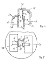
- the first waveguide 1 is also square.
- the one linearly polarized waveguide wave type does not propagate in the extended axial direction to the waveguide 1, but is coupled out via a separate coupling-out window 5 ', which runs centrally in the longitudinal direction on the one in FIG. 4 shown left side wall of the waveguide 1 is introduced. This is followed by an angle 27 for reversing the direction.
- the decoupling of the second linearly polarized and perpendicular to the first wave type wave type according to the invention takes place via the coupling window 5 in FIG. 4 on the opposite right side of the waveguide 1, which is attached there eccentrically in the waveguide 1, as can be seen particularly in FIG. 5 is.
- the second type of waveguide wave is decoupled while rotating the plane of polarization and also reversed in the direction by a subsequent angle 25.
- a short circuit 9' is attached.
- a waveguide termination 31 is provided at the end of the direction of propagation to the waveguide 1.
- the rectangular waveguide emanating from the waveguide 1 to the coupling or decoupling window 5 or 5 ' are aligned with one another with their narrow sides
- those after the coupling window 5 continuous waveguide branches 13 and 17 are aligned with one another with their broad side.
- the two polarization gates 19 and 21 belonging to the two waveguide branches 13 and 17 can lie in a common plane.
Landscapes
- Waveguide Switches, Polarizers, And Phase Shifters (AREA)
- Optical Integrated Circuits (AREA)
- Waveguide Connection Structure (AREA)
- Semiconductor Lasers (AREA)
Applications Claiming Priority (2)
| Application Number | Priority Date | Filing Date | Title |
|---|---|---|---|
| DE3824150 | 1988-07-16 | ||
| DE3824150A DE3824150A1 (de) | 1988-07-16 | 1988-07-16 | Hohlleiter-twist |
Publications (3)
| Publication Number | Publication Date |
|---|---|
| EP0351514A2 true EP0351514A2 (fr) | 1990-01-24 |
| EP0351514A3 EP0351514A3 (en) | 1990-09-05 |
| EP0351514B1 EP0351514B1 (fr) | 1994-11-09 |
Family
ID=6358813
Family Applications (1)
| Application Number | Title | Priority Date | Filing Date |
|---|---|---|---|
| EP89108556A Expired - Lifetime EP0351514B1 (fr) | 1988-07-16 | 1989-05-12 | Guide d'ondes à torsade |
Country Status (3)
| Country | Link |
|---|---|
| EP (1) | EP0351514B1 (fr) |
| AT (1) | ATE114077T1 (fr) |
| DE (2) | DE3824150A1 (fr) |
Cited By (5)
| Publication number | Priority date | Publication date | Assignee | Title |
|---|---|---|---|---|
| DE4009288A1 (de) * | 1990-03-22 | 1991-09-26 | Siemens Ag | Rechteckhohlleiter mit e-h-doppelversatz |
| WO2005099026A1 (fr) * | 2004-03-30 | 2005-10-20 | Murata Manufacturing Co., Ltd. | Coin de guide d'onde et dispositif radio |
| WO2010056609A2 (fr) * | 2008-11-11 | 2010-05-20 | Viasat, Inc. | Transducteur orthomode intégré |
| JP2013207391A (ja) * | 2012-03-27 | 2013-10-07 | Mitsubishi Electric Corp | 方形導波管の接続構造 |
| CN105140610A (zh) * | 2015-09-08 | 2015-12-09 | 安徽四创电子股份有限公司 | 一种用于脊波导缝隙天线阵的等效180°脊波导弯 |
Families Citing this family (3)
| Publication number | Priority date | Publication date | Assignee | Title |
|---|---|---|---|---|
| FR2904478B1 (fr) * | 2006-07-28 | 2010-04-23 | Cit Alcatel | Dispositif de transduction orthomode a compacite optimisee dans le plan de maille, pour une antenne |
| DE102009007317A1 (de) * | 2009-02-03 | 2010-08-12 | Continental Automotive Gmbh | Ventil |
| CN105071006B (zh) * | 2015-08-31 | 2017-09-29 | 北京遥测技术研究所 | 一种新型正交模耦合器 |
Citations (7)
| Publication number | Priority date | Publication date | Assignee | Title |
|---|---|---|---|---|
| US2731602A (en) * | 1946-01-10 | 1956-01-17 | Julian S Schwinger | Directional coupler |
| GB795862A (en) * | 1954-10-29 | 1958-06-04 | Western Electric Co | Improvements in or relating to transmission line coupling devices |
| US2883628A (en) * | 1957-06-25 | 1959-04-21 | Whilden G Heinard | Reverse direction waveguide coupler |
| DE976910C (de) * | 1939-01-24 | 1964-07-23 | Siemens Ag | Hohlleiteranordnung zur Drehung der Polarisationsrichtung elektromagnetischer Schwingungen |
| GB1018173A (en) * | 1962-11-20 | 1966-01-26 | Microwave Ass | A rectangular waveguide section |
| FR2057237A5 (fr) * | 1969-08-07 | 1971-05-21 | Thomson Csf | |
| DE2748956A1 (de) * | 1977-11-02 | 1979-05-03 | Licentia Gmbh | Hohlleitertwist |
Family Cites Families (3)
| Publication number | Priority date | Publication date | Assignee | Title |
|---|---|---|---|---|
| GB1591719A (en) * | 1976-12-21 | 1981-06-24 | Arconi Co Ltd | Orthogonal mode transducers |
| DE3010360C2 (de) * | 1980-03-18 | 1985-08-08 | Siemens AG, 1000 Berlin und 8000 München | Polarisationsweiche |
| DE3345689A1 (de) * | 1983-12-16 | 1985-07-11 | Messerschmitt-Bölkow-Blohm GmbH, 8012 Ottobrunn | Breitband-polarisationsweiche |
-
1988
- 1988-07-16 DE DE3824150A patent/DE3824150A1/de active Granted
-
1989
- 1989-05-12 AT AT89108556T patent/ATE114077T1/de active
- 1989-05-12 EP EP89108556A patent/EP0351514B1/fr not_active Expired - Lifetime
- 1989-05-12 DE DE58908620T patent/DE58908620D1/de not_active Expired - Fee Related
Patent Citations (7)
| Publication number | Priority date | Publication date | Assignee | Title |
|---|---|---|---|---|
| DE976910C (de) * | 1939-01-24 | 1964-07-23 | Siemens Ag | Hohlleiteranordnung zur Drehung der Polarisationsrichtung elektromagnetischer Schwingungen |
| US2731602A (en) * | 1946-01-10 | 1956-01-17 | Julian S Schwinger | Directional coupler |
| GB795862A (en) * | 1954-10-29 | 1958-06-04 | Western Electric Co | Improvements in or relating to transmission line coupling devices |
| US2883628A (en) * | 1957-06-25 | 1959-04-21 | Whilden G Heinard | Reverse direction waveguide coupler |
| GB1018173A (en) * | 1962-11-20 | 1966-01-26 | Microwave Ass | A rectangular waveguide section |
| FR2057237A5 (fr) * | 1969-08-07 | 1971-05-21 | Thomson Csf | |
| DE2748956A1 (de) * | 1977-11-02 | 1979-05-03 | Licentia Gmbh | Hohlleitertwist |
Non-Patent Citations (1)
| Title |
|---|
| NTZ NACHRICHTECHNISCHE ZEITSCHRIFT. vol. 38, no. 8, August 1985, BERLIN DE Seiten 554 - 560; E.SCHUEGRAF: "Neuartige Mikrowellenweichen für Zweibandantennen" * |
Cited By (8)
| Publication number | Priority date | Publication date | Assignee | Title |
|---|---|---|---|---|
| DE4009288A1 (de) * | 1990-03-22 | 1991-09-26 | Siemens Ag | Rechteckhohlleiter mit e-h-doppelversatz |
| WO2005099026A1 (fr) * | 2004-03-30 | 2005-10-20 | Murata Manufacturing Co., Ltd. | Coin de guide d'onde et dispositif radio |
| US7750762B2 (en) | 2004-03-30 | 2010-07-06 | Murata Manufacturing Co., Ltd. | Waveguide corner and radio device |
| WO2010056609A2 (fr) * | 2008-11-11 | 2010-05-20 | Viasat, Inc. | Transducteur orthomode intégré |
| WO2010056609A3 (fr) * | 2008-11-11 | 2010-11-18 | Viasat, Inc. | Transducteur orthomode intégré |
| JP2013207391A (ja) * | 2012-03-27 | 2013-10-07 | Mitsubishi Electric Corp | 方形導波管の接続構造 |
| CN105140610A (zh) * | 2015-09-08 | 2015-12-09 | 安徽四创电子股份有限公司 | 一种用于脊波导缝隙天线阵的等效180°脊波导弯 |
| CN105140610B (zh) * | 2015-09-08 | 2018-03-02 | 安徽四创电子股份有限公司 | 一种用于脊波导缝隙天线阵的等效180°脊波导弯 |
Also Published As
| Publication number | Publication date |
|---|---|
| ATE114077T1 (de) | 1994-11-15 |
| EP0351514A3 (en) | 1990-09-05 |
| DE3824150A1 (de) | 1989-07-06 |
| DE58908620D1 (de) | 1994-12-15 |
| EP0351514B1 (fr) | 1994-11-09 |
| DE3824150C2 (fr) | 1989-11-23 |
Similar Documents
| Publication | Publication Date | Title |
|---|---|---|
| DE3241890C2 (fr) | ||
| EP2535978B1 (fr) | Coupleur d'orthomodes pour un système d'antennes | |
| EP0351514B1 (fr) | Guide d'ondes à torsade | |
| DE60319512T2 (de) | Drehgelenk | |
| EP0089414B1 (fr) | Joint rotatif pour guide d'ondes | |
| DE3617359C1 (de) | 3-dB-Richtkoppler | |
| DE2800266C2 (de) | Kompensations-Anordnung für zwei miteinander axial fluchtende und einander stoßende Rechteck-Hohlleiter gleichen Querschnitts | |
| EP1266423B1 (fr) | Resonateur a cavite a frequence de resonance reglable | |
| DE2842576A1 (de) | Polarisationsweiche | |
| EP0147693B1 (fr) | Filtre de polarisation à large bande | |
| DE19922709A1 (de) | Polarisationsweiche | |
| DE2708271C2 (de) | Polarisationsweiche | |
| DE19839889C1 (de) | Übergang zwischen zwei um 45 DEG gegeneinander verdrehten Quadrathohlleitern | |
| DE3822981C2 (fr) | ||
| EP3331089B1 (fr) | Couplage orthomode permettant de réduire un couplage de modes fondamentaux | |
| DE2161895B2 (de) | Hohlleiterfibergang | |
| EP0419892B1 (fr) | Filtre de polarisation aux micro-ondes | |
| DE2747632C2 (de) | Antennenspeisesystem für Doppelpolarisation | |
| DE2737125A1 (de) | Uebertragungsleitungssystem | |
| WO2023222592A1 (fr) | Dispositif pour combiner ou diviser les micro-ondes | |
| EP0280151B1 (fr) | Filtre de polarisation aux micro-ondes | |
| EP0374720B1 (fr) | Convertisseur de mode | |
| DE2603348C3 (de) | Übergangsleitungsstück und damit aufgebaute Anordnung zur Kopplung zwischen Koaxialleitungen und einer konzentrischen Mehrfachleitung sowie deren Verwendung | |
| DE1231770B (de) | UEbergang hoher Belastbarkeit von einer Hohlleiterwelle auf eine Koaxialleitungswelle | |
| DE1466325B2 (de) | Wellentypwandler zur umwandlung des h tief 10 -wellentyps des rrechteckhohlleiters in den h tief 01 -wellentyp des rundhohlleiters |
Legal Events
| Date | Code | Title | Description |
|---|---|---|---|
| PUAI | Public reference made under article 153(3) epc to a published international application that has entered the european phase |
Free format text: ORIGINAL CODE: 0009012 |
|
| AK | Designated contracting states |
Kind code of ref document: A2 Designated state(s): AT BE CH DE FR GB LI NL SE |
|
| PUAL | Search report despatched |
Free format text: ORIGINAL CODE: 0009013 |
|
| AK | Designated contracting states |
Kind code of ref document: A3 Designated state(s): AT BE CH DE FR GB LI NL SE |
|
| 17P | Request for examination filed |
Effective date: 19910206 |
|
| 17Q | First examination report despatched |
Effective date: 19930505 |
|
| GRAA | (expected) grant |
Free format text: ORIGINAL CODE: 0009210 |
|
| AK | Designated contracting states |
Kind code of ref document: B1 Designated state(s): AT BE CH DE FR GB LI NL SE |
|
| PG25 | Lapsed in a contracting state [announced via postgrant information from national office to epo] |
Ref country code: NL Effective date: 19941109 Ref country code: BE Effective date: 19941109 |
|
| REF | Corresponds to: |
Ref document number: 114077 Country of ref document: AT Date of ref document: 19941115 Kind code of ref document: T |
|
| REF | Corresponds to: |
Ref document number: 58908620 Country of ref document: DE Date of ref document: 19941215 |
|
| ET | Fr: translation filed | ||
| PG25 | Lapsed in a contracting state [announced via postgrant information from national office to epo] |
Ref country code: SE Effective date: 19950209 |
|
| GBT | Gb: translation of ep patent filed (gb section 77(6)(a)/1977) |
Effective date: 19950116 |
|
| NLV1 | Nl: lapsed or annulled due to failure to fulfill the requirements of art. 29p and 29m of the patents act | ||
| PG25 | Lapsed in a contracting state [announced via postgrant information from national office to epo] |
Ref country code: LI Effective date: 19950531 Ref country code: CH Effective date: 19950531 |
|
| PLBE | No opposition filed within time limit |
Free format text: ORIGINAL CODE: 0009261 |
|
| STAA | Information on the status of an ep patent application or granted ep patent |
Free format text: STATUS: NO OPPOSITION FILED WITHIN TIME LIMIT |
|
| 26N | No opposition filed | ||
| REG | Reference to a national code |
Ref country code: CH Ref legal event code: PL |
|
| PGFP | Annual fee paid to national office [announced via postgrant information from national office to epo] |
Ref country code: DE Payment date: 19990305 Year of fee payment: 11 |
|
| PGFP | Annual fee paid to national office [announced via postgrant information from national office to epo] |
Ref country code: GB Payment date: 19990324 Year of fee payment: 11 |
|
| PGFP | Annual fee paid to national office [announced via postgrant information from national office to epo] |
Ref country code: FR Payment date: 19990420 Year of fee payment: 11 |
|
| PGFP | Annual fee paid to national office [announced via postgrant information from national office to epo] |
Ref country code: AT Payment date: 19990520 Year of fee payment: 11 |
|
| PG25 | Lapsed in a contracting state [announced via postgrant information from national office to epo] |
Ref country code: GB Free format text: LAPSE BECAUSE OF NON-PAYMENT OF DUE FEES Effective date: 20000512 Ref country code: AT Free format text: LAPSE BECAUSE OF NON-PAYMENT OF DUE FEES Effective date: 20000512 |
|
| GBPC | Gb: european patent ceased through non-payment of renewal fee |
Effective date: 20000512 |
|
| PG25 | Lapsed in a contracting state [announced via postgrant information from national office to epo] |
Ref country code: FR Free format text: LAPSE BECAUSE OF NON-PAYMENT OF DUE FEES Effective date: 20010131 |
|
| PG25 | Lapsed in a contracting state [announced via postgrant information from national office to epo] |
Ref country code: DE Free format text: LAPSE BECAUSE OF NON-PAYMENT OF DUE FEES Effective date: 20010301 |
|
| REG | Reference to a national code |
Ref country code: FR Ref legal event code: ST |