EP0348955A2 - Aufnahme- und Wiedergabesystem für optische Platte mit Behandlungsdatenzugriffsmechanismus - Google Patents
Aufnahme- und Wiedergabesystem für optische Platte mit Behandlungsdatenzugriffsmechanismus Download PDFInfo
- Publication number
- EP0348955A2 EP0348955A2 EP89111801A EP89111801A EP0348955A2 EP 0348955 A2 EP0348955 A2 EP 0348955A2 EP 89111801 A EP89111801 A EP 89111801A EP 89111801 A EP89111801 A EP 89111801A EP 0348955 A2 EP0348955 A2 EP 0348955A2
- Authority
- EP
- European Patent Office
- Prior art keywords
- data
- directory data
- sector
- directory
- recording
- Prior art date
- Legal status (The legal status is an assumption and is not a legal conclusion. Google has not performed a legal analysis and makes no representation as to the accuracy of the status listed.)
- Granted
Links
Images


Classifications
-
- G—PHYSICS
- G11—INFORMATION STORAGE
- G11B—INFORMATION STORAGE BASED ON RELATIVE MOVEMENT BETWEEN RECORD CARRIER AND TRANSDUCER
- G11B7/00—Recording or reproducing by optical means, e.g. recording using a thermal beam of optical radiation by modifying optical properties or the physical structure, reproducing using an optical beam at lower power by sensing optical properties; Record carriers therefor
- G11B7/007—Arrangement of the information on the record carrier, e.g. form of tracks, actual track shape, e.g. wobbled, or cross-section, e.g. v-shaped; Sequential information structures, e.g. sectoring or header formats within a track
- G11B7/00736—Auxiliary data, e.g. lead-in, lead-out, Power Calibration Area [PCA], Burst Cutting Area [BCA], control information
Definitions
- the present invention relates to an optical disk recording and reading system for recording data on and reading data from an optical disk which has a plurality of sectors, the optical disk recording and reading system having a management data access mechanism.
- FIG. 15 of the accompanying drawings shows a data file structure for such a WORM optical disk, the data file structure having a user data area and a directory data area. More specifically, the data file structure includes a user data area 2 which stores user data 1, a directory data area 4 which stores directory data 3 including latest directory data 5, and a virgin area 6. One track corresponds to one circular path on the optical disk.
- the directory data 3 contain the file name, address information, size, and attributes of the recorded user data 1.
- the directory data 3 are read by the system.
- the directory data 3 are updated each time data are subsequently recorded on and read from the optical disk.
- updated latest directory data 5 are newly recorded in a leading sector of the virgin area 6. Therefore, the latest directory data 5 are always recorded in the final sector in the directory data 3 recorded in the directory data area 4, i.e., in the sector at the boundary between the directory data area 4 and the virgin area 6.
- the directory data area 4 is sequentially searched from its leading end until a first virgin sector is detected, and the directory data 3 recorded immediately in front of the detected virgin sector are read as the latest directory data 5.
- data can be recorded on an optical disk by burning pits each 1 ⁇ m in diameter into the disk surface with a small spot of a laser beam emitted from a semiconduc tor laser, and recorded data can be read from the optical disk by applying a laser beam to pits and receiving a light beam reflected from and modulated by the pits.
- the pits are recorded in circular tracks which are radially at spacings of about 1.6 ⁇ m, i.e., two adjacent tracks are spaced from each other at an interval or pitch of 1.6 ⁇ m. Therefore, optical disks allow storage of large quantities of information at a high density.
- a crosstalk i.e., when data are being read from one sector on a track, a signal from an adjacent track may also be picked up and mixed into the signal from the sector being read out.
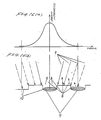
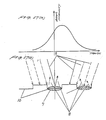
- FIG. 16(a) shows the intensity distribution of a laser beam spot on a recorded surface of an optical disk
- FIG. 16(b) is a radial cross-sectional view of the recorded surface.
- the recorded surface has pits 7 along tracks 10 which were burned as data by a laser beam.
- a laser beam 9 from a semiconductor laser is applied to the recorded surface, a light beam 8 which is modulated by the pits 7 is reflected from the recorded surface.
- the intensity of the laser beam applied to the recorded surface spreads into adjacent tracks, with different light intensi ties being indicated by the solid-line and broken-line arrows in FIG. 16(b). Even if the laser beam is well converged by an optical lens, it is impossible to focus the laser beam spot solely on the desired track, and light of a small intensity is always applied to the adjacent tracks. Accordingly, some weak noise due to crosstalk has been unavoidable.
- FIGS. 17(a) and 17(b) show the intensity distribution of an applied laser beam and the manner in which light is reflected, respectively, when the laser beam suffers from focusing and tracking errors.
- a crosstalk component from an adjacent track is increased.
- the crosstalk-dependent light beam reflection is however much smaller than the normal light beam 8 reflected from the desired track. Any crosstalk caused by such focusing and tracking errors has been practically harmless insofar as the track containing recorded data pits is read.
- This erroneous crosstalk signal readout is problematic in that a virgin sector on an optical disk may not fully be confirmed as a virgin sector.
- the aforesaid system for detecting directory data based on the detection of a virgin sector may not be reliable in operation.
- an object of the present invention to provide an optical disk recording and reading system having a directory data access mechanism which is capable of detecting directory data with high reliability.
- an optical disk recording and reading system includes an optical disk having a data file structure including a user data area for recording user data and a directory data area for recording directory data relating to the recorded user data, the directory data area having directory data recording sectors positioned such that they are not adjacent to each other in a direction transverse to tracks on the optical disk.
- the directory data area has directory data recording sectors arranged in a checkerboard pattern. New directory data are recorded as latest directory data in a sector at the terminal end of the checkerboard pattern in the directory data area when user data are recorded in and read from the user data area. Since the sector storing the latest directory data is always flanked by virgin sectors on adjacent tracks, the latest directory data can be detected highly reliably without suffering from crosstalk noise from the adjacent tracks.
- the directory data area has directory data recording sectors on every other track therein. New directory data are recorded as latest directory data in a sector at the terminal end of the directory data area when user data are recorded in and read from the user data area. Since the sector storing the latest directory data is always flanked by virgin sectors on adjacent tracks, the latest directory data can be detected highly reliably without suffering from crosstalk noise from the adjacent tracks.
- old directory data are deleted from the directory data area, and the latest directory data can be detected by detecting the deletion of the old directory data.
- new directory data are recorded as latest directory data in a sector following the final sector in the directory data area from which the data have been deleted by data deleting means, and any previous latest directory data are deleted from the directory data area. Since old directory data are deleted, the latest directory data can be detected highly reliably by detecting the deletion of the directory data, without being subjected to crosstalk noise from the adjacent tracks.
- new directory data are recorded as latest directory data in a sector which is a predetermined number of sectors after the final sector in the directory data area from which the data have been deleted by data deleting means, and directory data are deleted from a sector which is a predetermined number of sectors before the sector recording the latest directory data. Since old directory data in the sectors which are the predetermined number of sectors before the latest directory data are deleted, the latest directory data can be detected highly reliably by detecting the deletion of the directory data, without being subjected to crosstalk noise from the adjacent tracks.
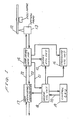
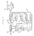
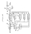
- FIG. 1 shows an optical disk recording and reading system having a directory data access mechanism according to a first embodiment of the present invention.
- the optical disk recording and reading system shown in FIG. 1 includes an optical disk 12 rotatable by a disk motor, an optical head 13 having a semiconductor laser or the like for emitting a laser beam, a laser driver/head amplifier 14 for driving the semiconductor laser of the optical head 13 and amplifying a weak reflection signal detected by the optical head 13, a focus control circuit 15 for controlling the focusing of the laser beam based on a focus error signal from the laser driver/head amplifier 14, a tracking control circuit 16 for controlling the tracking of the laser beam based on a tracking error signal from the laser driver/head amplifier 14, a data modulator/demodulator 17 for digitally modulating data which have been encoded by an error correcting code and for demodulating data read from the optical disk 12, a sector control circuit 18 for searching, record ing data in, and reading data from, a desired sector on the optical disk 12, and a control central processing unit (CPU)
- the control CPU 19 first sends an address 20 of a desired sector in which the data are to be recorded, to the sector control circuit 18.
- the sector control circuit 18 controls the tracking control circuit 16 to seek a track which contains the desired sector.
- the sector control circuit 18 compares a sector address 21 delivered from the laser driver/head amplifier 14 with the address 20 of the desired sector. When the compared addresses 21, 20 coincide with each other, the sector control circuit 18 operates the data modulator/demodulator 17 to start modulating the data.
- the laser driver/head amplifier 14 drives the semiconductor laser of the optical head 13 in response to modulated data 22 from the data modulator/demodulator 17.
- the optical head 13 emits a laser beam to burn pits 7 into the recording surface of the optical disk 12.
- Recorded data are read from the optical disk 12 as follows: After a desired sector from which the data are to be read has been sought in the same manner as when the data are recorded, the sector control circuit 18 operates the data modulator/demodulator 17 to start demodulating the data.
- the data modulator/demodulator 17 demodulates read-out binary data 23 from the laser driver/head amplifier 14, and sends the demodulated data to an error correcting circuit (not shown).
- the optical disk recording and reading system of the first embodiment can thus record data on and read data from the optical disk 12 by addressing the desired sector with the control CPU 19.
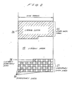
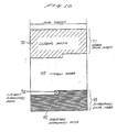
- FIG. 2 illustrates a data file structure of the optical disk 12 on and from which data can be recorded and read by the optical disk recording and reading system shown in FIG. 1.
- the data file structure includes a user data area 25 which stores user data 24, a directory data area 27 which stores directory data 26 including latest directory data 28, and a virgin area 29.
- One track corresponds to one circular path on the optical disk 12.
- directory data are recorded in every other sector such that the sectors in two adjacent tracks are not positioned adjacent to each other and hence the recorded sectors are not disposed adjacent to each other in both circumferential and radial directions of the optical disk 12.
- the recorded sectors are of a checkerboard pattern.
- the latest directory data 28 are recorded in the sector at the terminal end of the directory data area 29, i.e., in the sector at the boundary between the directory data area 29 and the virgin area 29.
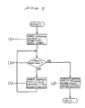
- control CPU 19 controls the optical disk recording and reading system to detect the address of the sector which stores the latest directory data 28 according to the sequence of the following steps:
- the latest directory data 28 may be updated by detecting the latest directory data 28 according to the sequence of the steps (a) through (d) described above and thereafter recording new directory data in a sector which is the second sector after the sector which stores the present latest directory data 28.
- FIG. 4 illustrates an optical disk recording and reading system having a directory data access mechanism according to a second embodiment of the present invention.
- the optical disk recording and reading system shown in FIG. 4 includes an optical disk 35 rotatable by a disk motor, an optical head 36 having a semiconductor laser or the like for emitting a laser beam, a laser driver/head amplifier 37 for driving the semiconductor laser of the optical head 36 and amplifying a weak reflection signal detected by the optical head 36, a focus control circuit 38 for controlling the focusing of the laser beam based on a focus error signal from the laser driver/head amplifier 37, a tracking control circuit 39 for controlling the tracking of the laser beam based on a tracking error signal from the laser driver/head amplifier 37, a data modulator/demodulator 40 for digitally modulating data which have been encoded by an error correcting code and for demodulating data read from the optical disk 35, a sector control circuit 41 for searching, recording data in, and reading data from, a desired sector on the optical disk 35, and a control central processing unit
- Data are recorded on the optical disk 35 as follows:
- the control CPU 42 first sends an address 43 of a desired sector in which the data are to be recorded, to the sector control circuit 41.
- the sector control circuit 42 controls the tracking control circuit 39 to seek a track which contains the desired sector.
- the sector control circuit 41 compares a sector address 44 delivered from the laser driver/head amplifier 37 with the address 43 of the desired sector. When the compared addresses 44, 43 coincide with each other, the sector control circuit 41 operates the data modulator/demodulator 40 to start modulating the data.
- the laser driver/head amplifier 37 drives the semiconductor laser of the optical head 36 in response to modulated data 45 from the data modulator/demodulator 40.
- the optical head 36 emits a laser beam to burn pits 7 into the recording surface of the optical disk 35.
- Recorded data are read from the optical disk 35 as follows: After a desired sector from which the data are to be read has been sought in the same manner as when the data are recorded, the sector control circuit 41 operates the data modulator/demodulator 40 to start demodulating the data.
- the data modulator/demodulator 40 demodulates read-out binary data 46 from the laser driver/head amplifier 37, and sends the demodulated data to an error correcting circuit (not shown).
- the optical disk recording and reading system of the second embodiment can thus record data on and read data from the optical disk 35 by addressing the desired sector with the control CPU 42.
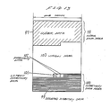
- FIG. 5 shows a data file structure of the optical disk 35 on and from which data can be recorded and read by the optical disk recording and reading system shown in FIG. 4.
- the data file structure includes a user data area 104 which stores user data 109, a directory data area 105 which stores directory data 106 including latest directory data 107, and a virgin area 108.
- One track corresponds to one circular path on the optical disk 35.
- the directory data area 105 is composed of sectors on an nth track a (n + 2)th track, and a (n + 4)th track, i.e., on every other track.
- the latest directory data 107 are recorded in the sector at the terminal end of the directory data area 105, i.e., in the sector at the boundary between the directory data area 105 and the virgin area 108.
- control CPU 42 controls the optical disk recording and reading system to detect the address of the sector which stores the latest directory data 107 according to the sequence of the following steps:
- the directory data area 107 is composed of sectors on every other track, a sector on a track in the directory data area 107, which is being checked for being a virgin sector, is flanked by virgin sectors on adjacent tracks, and hence can be checked highly reliably because no undesirable crosstalk signals are produced from those virgin sectors on the adjacent tracks.
- Virgin sectors can easily be detected by the laser driver/head amplifier 37 which effects envelope detection based on whether the read signal contains a modulated signal or not.
- the latest directory data 107 may be updated by detecting the latest directory data 107 according to the sequence of the steps (a) through (e) described above, and, if the sector storing the latest directory data 107 is the final sector, by thereafter recording new directory data in the first sector on the next but one track, or if the sector storing the latest directory data 107 is not the final sector, by thereafter recording new directory data in the next sector.
- FIG. 7 shows an optical disk recording and reading system having a directory data access mechanism according to a third embodiment of the present invention.
- the optical disk recording and reading system shown in FIG. 7 includes an optical disk 47 rotatable by a disk motor, an optical head 48 having a semiconductor laser or the like for emitting a laser beam, a laser driver/head amplifier 49 for driving the semiconductor laser of the optical head 48 and amplifying a weak reflection signal detected by the optical head 48, a focus control circuit 50 for controlling the focusing of the laser beam based on a focus error signal from the laser driver/head amplifier 49, a tracking control circuit 51 for controlling the tracking of the laser beam based on a tracking error signal from the laser driver/head amplifier 49, a data modulator/demodulator 52 for digitally modulating data which have been encoded by an error correcting code and for demodulating data read from the optical disk 47, a sector control circuit 53 for searching, recording data in, and reading data from, a desired sector on the optical disk 47, a control central processing unit (
- Data are recorded on the optical disk 47 as follows:
- the control CPU 54 first sends an address 67 of a desired sector in which the data are to be recorded, to the sector control circuit 53.
- the sector control circuit 53 controls the tracking control circuit 51 to seek a track which contains the desired sector.
- the sector control circuit 53 compares a sector address 68 delivered from the laser driver/head amplifier 49 with the address 67 of the desired sector. When the compared addresses 68, 67 coincide with each other, the sector control circuit 53 operates the data modulator/demodulator 52 to start modulating the data.
- the laser driver/head amplifier 49 drives the semiconductor laser of the optical head 48 in response to modulated data 69 from the data modulator/demodulator 52.
- the optical head 48 emits a laser beam to burn pits 7 into the recording surface of the optical disk 47.
- Recorded data are read from the optical disk 47 as follows: After a desired sector from which the data are to be read has been sought in the same manner as when the data are recorded, the sector control circuit 53 operates the data modulator/demodulator 52 to start demodulating the data.
- the data modulator/demodulator 52 demodulates read-out binary data from the laser driver/head amplifier 49, and sends the demodulated data to an error correcting circuit (not shown).
- the optical disk recording and reading system of the third embodiment can thus record data on and read data from the optical disk 47 by addressing the desired sector with the control CPU 54.
- FIG. 10 shows a data file structure of the optical disk 47 on and from which data can be recorded and read by the optical disk recording and reading system shown in FIG. 7.
- the data file structure includes a user data area 71 which stores user data 70, a directory data area 73 which stores deleted directory data 72 and latest directory data 74, and a virgin area 75.
- One track corresponds to one circular path on the optical disk 47.
- the directory data area 73 In the directory data area 73, all old directory data except the latest directory data 74 are deleted by signals from the deletion signal generator 55.
- the latest directory data 74 are recorded in the sector at the terminal end of the directory data area 73, i.e., in the sector at the boundary between the directory data area 73 and the virgin area 75.
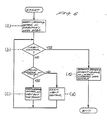
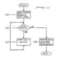
- a process of detecting the latest directory data 74 from the directory data area 73 will be described below with reference to FIG. 11.
- the control CPU 54 controls the optical disk recording and reading system to detect the address of the sector which stores the latest directory data 74 according to the sequence of the following steps:
- the latest directory data can be detected without checking if the sectors in the directory data area 73 are virgin sectors or not. Therefore, the latest directory data 74 can be detected highly reliably because no undesirable crosstalk signals are applied from the adjacent tracks.
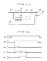
- FIG. 8(a) shows the deletion signal generator 55 in detail
- FIG. 8(b) a timing chart of signals produced in the deletion signal generator 55.
- the deletion signal generator 55 includes a timer A 76 activatable by a sector detection signal 57 for producing a high-level signal for a period T1, a timer B 77 activatable by the sector detection signal 57 for producing a high-level signal for a period T2, and gates 78, 79.
- a delete enable signal 58 is produced from the control CPU 54.
- the sector control circuit 53 When the desired sector is detected, the sector control circuit 53 generates a sector detection signal 57 which is high for a time period corresponding to the interval of that sector.
- the timer A 76 and the timer B 77 are started, and a deletion signal 59 is produced from the output signals from these timers.
- the deletion signal 59 is then sent to the laser driver/head amplifier 49.
- the deletion signal 59 which is a DC signal can thus be recorded in a portion of the sector by the deletion signal generator thus constructed, so that the data can be deleted from the sector.
- FIG. 9(a) shows the deletion signal detector 56 in detail
- FIG. 9(b) a timing chart of signals produced in the deletion signal detector 56.
- the deletion signal detector 56 can detect the sector from which the data are deleted by the deletion signal generator shown in FIG. 8(a).
- the deletion signal detector 56 has a timer C 80 activatable by the sector detection signal 57 for producing a high-level signal after a period T3, a timer B 81 activatable by the sector detection signal 57 for producing a high-level signal after a period T4, a sample and hold circuit A 82 for sampling and holding a signal in response to a hold signal 63, and a sample and hold circuit B 83 for sampling and holding a signal in response to a hold signal 64.
- the timers A 80 and B 81 are started by the sector detection signal 57 to enable the sample and hold circuits A 82, B83 to sample and hold an envelope detection signal 62 of a read-out sector signal from the laser driver/head amplifier 49.
- the envelope detection signal 62 is of one of signal levels shown in FIG. 9(b) dependent on whether data are recorded, not recorded, or deleted in the sector.
- the data in the sector are determined as being deleted when output signals 65, 66 from the sample and hold circuits A 82, B 83 are low and high, respectively.
- the data in a sector can be deleted by recording a DC signal on a portion of the sector, and the sector from which the data are thus deleted can be detected.
- the latest directory data 74 may be updated by detecting the latest directory data 74 according to the sequence of the steps (a) through (d) described above, then recording new directory data in the sector next to the sector which stores the latest directory data 74, and deleting the latest directory data 74 from the sector as described above.
- the latest directory data 74 can be detected highly reliably simply by detecting the data deletion without detecting virgin sectors.
- FIG. 12 shows an optical disk recording and reading system having a directory data access mechanism according to a fourth embodiment of the present invention.
- the optical disk recording and reading system shown in FIG. 12 includes an optical disk 84 rotatable by a disk motor, an optical head 85 having a semiconductor laser or the like for emitting a laser beam, a laser driver/head amplifier 86 for driving the semiconductor laser of the optical head 85 and amplifying a weak reflection signal detected by the optical head 85, a focus control circuit 87 for controlling the focusing of the laser beam based on a focus error signal from the laser driver/head amplifier 86, a tracking control circuit 88 for controlling the tracking of the laser beam based on a tracking error signal from the laser driver/head amplifier 86, a data modulator/demodulator 89 for digitally modulating data which have been encoded by an error correcting code and for demodulating data read from the optical disk 85, a sector control circuit 90 for searching, recording data in, and reading data from, a desired sector on the optical disk 84
- Data are recorded on the optical disk 84 as follows:
- the control CPU 91 first sends an address 94 of a desired sector in which the data are to be recorded, to the sector control circuit 90.
- the sector control circuit 90 controls the tracking control circuit 88 to seek a track which contains the desired sector.
- the sector control circuit 90 compares a sector address 95 delivered from the laser driver/head amplifier 86 with the address 94 of the desired sector. When the compared addresses 95, 94 coincide with each other, the sector control circuit 90 operates the data modulator/demodulator 89 to start modulating the data.
- the laser driver/head amplifier 86 drives the semiconductor laser of the optical head 85 in response to modulated data 96 from the data modulator/demodulator 89.
- the optical head 85 emits a laser beam to burn pits 7 into the recording surface of the optical disk 84.
- Recorded data are read from the optical disk 84 as follows: After a desired sector from which the data are to be read has been sought in the same manner as when the data are recorded, the sector control circuit 90 operates the data modulator/demodulator 89 to start demodulating the data.
- the data modulator/demodulator 89 demodulates read-out binary data from the laser driver/head amplifier 86, and sends the demodulated data to an error correcting circuit (not shown).
- the optical disk recording and reading system of the third embodiment can thus record data on and read data from the optical disk 84 by addressing the desired sector with the control CPU 91.
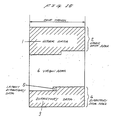
- FIG. 13 shows a data file structure of the optical disk 84 on and from which data can be recorded and read by the optical disk recording and reading system shown in FIG. 12.
- the data file structure includes a user data area 98 which stores user data 97, a directory data area 100 which stores deleted directory data 99, latest directory data 101, and directory data 102, and a virgin area 103.
- One track corresponds to one circular path on the optical disk 84.
- the directory data area 100 all old directory data except the latest directory data 101 and the directory data 102 in two sectors are deleted by signals from the deletion signal generator 92.
- the latest directory data 101 are recorded in the sector at the terminal end of the directory data area 100, i.e., in the third sector as counted from, or after, the end of the deleted directory data 99.
- control CPU 91 controls the optical disk recording and reading system to detect the address of the sector which stores the latest directory data 101 according to the sequence of the following steps:
- the latest directory data can be detected without checking if the sectors in the directory data area 100 are virgin sectors or not. Therefore, the latest directory data 101 can be detected highly reliably because no undesirable crosstalk signals are applied from the adjacent tracks.
- Deletion of the data from the recorded sectors and detection of the sectors from which the data are deleted can be carried out by the deletion signal generator 92 and the deletion signal detector 93 which may be constructed as shown in FIGS. 8(a), 9(a), or as disklosed in Japanese Laid-Open Patent Publications Nos. 60-115074 and 60-187971, for example.
- the latest directory data 101 may be updated by detecting the latest directory data 101 according to the sequence of the steps (a) through (d) described above, then recording new directory data in the sector next to the sector which stores the latest directory data 101, and deleting the data from the sector which is the second preceding sector as counted from, i.e., the second sector before the sector storing the latest directory data 101.
- the latest directory data 101 can be detected highly reliably simply by detecting the data deletion without detecting virgin sectors. Even if the latest directory data cannot be read for some reason, the available directory data which are left undeleted in the two sectors can be read out to provide directory information which minimizes the damage resulting from the unavailability of the latest directory data. Accordingly, the directory data can be detected highly reliably.
- Directory data relating to user data are recorded in sectors of a checkerboard pattern or in sectors on every other track in a directory data area on an optical disk.
- the sectors which store the directory data are always flanked by adjacent virgin sectors in a direction normal to the tracks. Therefore, the latest directory data can be detected highly reliably without crosstalk noise from adjacent tracks.
- old directory data except the latest directory data are deleted or old directory data except the latest directory data and directory data in a predetermined number of sectors before the latest directory data are deleted, and the latest directory data can be detected highly reliably by detecting the deletion of the directory data.
Landscapes
- Signal Processing For Digital Recording And Reproducing (AREA)
- Optical Recording Or Reproduction (AREA)
- Management Or Editing Of Information On Record Carriers (AREA)
- Information Retrieval, Db Structures And Fs Structures Therefor (AREA)
Applications Claiming Priority (2)
| Application Number | Priority Date | Filing Date | Title |
|---|---|---|---|
| JP160079/88 | 1988-06-28 | ||
| JP63160079A JP2578918B2 (ja) | 1988-06-28 | 1988-06-28 | 光ディスク記録再生装置 |
Publications (3)
| Publication Number | Publication Date |
|---|---|
| EP0348955A2 true EP0348955A2 (de) | 1990-01-03 |
| EP0348955A3 EP0348955A3 (de) | 1991-07-03 |
| EP0348955B1 EP0348955B1 (de) | 1994-04-13 |
Family
ID=15707418
Family Applications (1)
| Application Number | Title | Priority Date | Filing Date |
|---|---|---|---|
| EP89111801A Expired - Lifetime EP0348955B1 (de) | 1988-06-28 | 1989-06-28 | Aufnahme- und Wiedergabesystem für optische Platte mit Behandlungsdatenzugriffsmechanismus |
Country Status (4)
| Country | Link |
|---|---|
| US (1) | US5073887A (de) |
| EP (1) | EP0348955B1 (de) |
| JP (1) | JP2578918B2 (de) |
| DE (1) | DE68914523T2 (de) |
Families Citing this family (11)
| Publication number | Priority date | Publication date | Assignee | Title |
|---|---|---|---|---|
| JP2888958B2 (ja) * | 1990-10-20 | 1999-05-10 | 富士通株式会社 | 部分書き換え可能な記憶媒体におけるファイル管理方式 |
| US5347651A (en) * | 1991-04-23 | 1994-09-13 | International Business Machines Corporation | System for allocating worm optical medium file storage in groups of fixed size addressable areas while tracking unrecorded areas and end of volume |
| US5446857A (en) * | 1992-06-12 | 1995-08-29 | Unisys Corporation | Method and apparatus for writing files on nonerasable storage medium |
| US5437012A (en) * | 1993-04-19 | 1995-07-25 | Canon Information Systems, Inc. | System for updating directory information and data on write once media such as an optical memory card |
| JP3329289B2 (ja) * | 1998-11-26 | 2002-09-30 | インターナショナル・ビジネス・マシーンズ・コーポレーション | ディスクドライブ装置及びその製造方法、ディスクドライブ装置のシーク制御方法、ディスクドライブ制御装置 |
| US20030157292A1 (en) * | 1999-06-23 | 2003-08-21 | Dataplay, Inc. | Miniature optical disk for data storage |
| US6990058B1 (en) | 2000-04-03 | 2006-01-24 | Dphi Acquisitions, Inc. | Structure and method for storing data on optical disks |
| US7051054B1 (en) * | 2000-05-30 | 2006-05-23 | Dphi Acquisitions, Inc. | Method and apparatus for emulating read/write file system on a write-once storage disk |
| US6738333B1 (en) | 2000-05-30 | 2004-05-18 | Dphi Acquisitions, Inc. | Format for recording data in a storage disk |
| EP1436700A2 (de) * | 2000-05-30 | 2004-07-14 | DPHI Aquisitions, Inc. | Fehlerverwaltungssystem für einmal beschreibbare speicherplatte |
| US20030147338A1 (en) * | 2000-09-27 | 2003-08-07 | Akira Yoshikawa | Optical disk |
Family Cites Families (6)
| Publication number | Priority date | Publication date | Assignee | Title |
|---|---|---|---|---|
| JPS5832236A (ja) * | 1981-08-18 | 1983-02-25 | Matsushita Electric Ind Co Ltd | 光学的記録再生装置 |
| US4575827A (en) * | 1984-05-18 | 1986-03-11 | International Business Machines Corporation | Self-archiving data recording |
| JPS626321A (ja) * | 1985-07-02 | 1987-01-13 | Canon Inc | 非消去型記録媒体の記録方式 |
| EP0223353A3 (en) * | 1985-09-10 | 1988-07-20 | Canon Kabushiki Kaisha | Information record carrier |
| JPS6314379A (ja) * | 1986-07-07 | 1988-01-21 | Matsushita Electric Ind Co Ltd | 情報記録再生装置 |
| CA1320268C (en) * | 1986-09-10 | 1993-07-13 | Wataru Sakagami | Information record medium having an area for recording information indicating logical erasure of data and method for recording information on the same |
-
1988
- 1988-06-28 JP JP63160079A patent/JP2578918B2/ja not_active Expired - Fee Related
-
1989
- 1989-06-28 DE DE68914523T patent/DE68914523T2/de not_active Expired - Fee Related
- 1989-06-28 US US07/372,587 patent/US5073887A/en not_active Expired - Lifetime
- 1989-06-28 EP EP89111801A patent/EP0348955B1/de not_active Expired - Lifetime
Also Published As
| Publication number | Publication date |
|---|---|
| JPH0210575A (ja) | 1990-01-16 |
| JP2578918B2 (ja) | 1997-02-05 |
| DE68914523D1 (de) | 1994-05-19 |
| EP0348955A3 (de) | 1991-07-03 |
| EP0348955B1 (de) | 1994-04-13 |
| DE68914523T2 (de) | 1994-08-11 |
| US5073887A (en) | 1991-12-17 |
Similar Documents
| Publication | Publication Date | Title |
|---|---|---|
| EP0243503B1 (de) | Datenaufzeichnungs-wiedergabegerät | |
| US4545044A (en) | Method and apparatus for optically recording and reproducing information | |
| EP0089021B1 (de) | Gerät zur Verhütung von Doppelaufzeichnen einer optischen Scheibe | |
| US6628583B1 (en) | Method and device for recording information in linking block units | |
| US4695993A (en) | Optical information recording and reproducing apparatus and optical disc | |
| CN1121624A (zh) | 一次写入的光盘记录装置 | |
| EP0348955B1 (de) | Aufnahme- und Wiedergabesystem für optische Platte mit Behandlungsdatenzugriffsmechanismus | |
| US4768181A (en) | Apparatus for determining defective or non-used sectors of an optical dish | |
| SK8062001A3 (en) | Method of hiding areas on a disc like recording of the optically rewritable type | |
| KR20010075124A (ko) | 쓰기 방지된 결함 목록을 갖는 기록매체 | |
| JP4159616B2 (ja) | 光ディスク、その記録方法、その記録装置、その再生方法及びその再生装置 | |
| EA002300B1 (ru) | Способ хранения идентификации на носителе записи, устройство и носитель записи | |
| JPWO1999004391A1 (ja) | 光ディスク、その記録方法、その記録装置、その再生方法及びその再生装置 | |
| JPH0689452A (ja) | 光デイスク装置 | |
| US5161136A (en) | Servo error detecting method of an optical disc system | |
| JPH03245360A (ja) | 情報記録再生装置 | |
| JP2001202621A (ja) | 光ディスク、その記録方法、その記録装置、その再生方法及びその再生装置 | |
| JP3782208B2 (ja) | 光ディスク記録装置 | |
| JP3795319B2 (ja) | 光ディスク、その記録方法、その記録装置、その再生方法及びその再生装置 | |
| JPH03198223A (ja) | 情報の記録方法 | |
| JPH0338658B2 (de) | ||
| JPS59217206A (ja) | 情報処理装置 | |
| JP2001202623A (ja) | 光ディスク、その記録装置、その再生方法及びその再生装置 | |
| JPS60236120A (ja) | 情報の消去方法 | |
| JPH0787004B2 (ja) | データ記録方法 |
Legal Events
| Date | Code | Title | Description |
|---|---|---|---|
| PUAI | Public reference made under article 153(3) epc to a published international application that has entered the european phase |
Free format text: ORIGINAL CODE: 0009012 |
|
| 17P | Request for examination filed |
Effective date: 19890628 |
|
| AK | Designated contracting states |
Kind code of ref document: A2 Designated state(s): DE FR GB |
|
| PUAL | Search report despatched |
Free format text: ORIGINAL CODE: 0009013 |
|
| AK | Designated contracting states |
Kind code of ref document: A3 Designated state(s): DE FR GB |
|
| 17Q | First examination report despatched |
Effective date: 19930216 |
|
| GRAA | (expected) grant |
Free format text: ORIGINAL CODE: 0009210 |
|
| AK | Designated contracting states |
Kind code of ref document: B1 Designated state(s): DE FR GB |
|
| ET | Fr: translation filed | ||
| REF | Corresponds to: |
Ref document number: 68914523 Country of ref document: DE Date of ref document: 19940519 |
|
| PLBE | No opposition filed within time limit |
Free format text: ORIGINAL CODE: 0009261 |
|
| STAA | Information on the status of an ep patent application or granted ep patent |
Free format text: STATUS: NO OPPOSITION FILED WITHIN TIME LIMIT |
|
| 26N | No opposition filed | ||
| REG | Reference to a national code |
Ref country code: GB Ref legal event code: IF02 |
|
| PGFP | Annual fee paid to national office [announced via postgrant information from national office to epo] |
Ref country code: DE Payment date: 20030710 Year of fee payment: 15 |
|
| REG | Reference to a national code |
Ref country code: GB Ref legal event code: 746 Effective date: 20031002 |
|
| REG | Reference to a national code |
Ref country code: FR Ref legal event code: D6 |
|
| PGFP | Annual fee paid to national office [announced via postgrant information from national office to epo] |
Ref country code: FR Payment date: 20040608 Year of fee payment: 16 |
|
| PGFP | Annual fee paid to national office [announced via postgrant information from national office to epo] |
Ref country code: GB Payment date: 20040623 Year of fee payment: 16 |
|
| PG25 | Lapsed in a contracting state [announced via postgrant information from national office to epo] |
Ref country code: DE Free format text: LAPSE BECAUSE OF NON-PAYMENT OF DUE FEES Effective date: 20050101 |
|
| PG25 | Lapsed in a contracting state [announced via postgrant information from national office to epo] |
Ref country code: GB Free format text: LAPSE BECAUSE OF NON-PAYMENT OF DUE FEES Effective date: 20050628 |
|
| PG25 | Lapsed in a contracting state [announced via postgrant information from national office to epo] |
Ref country code: FR Free format text: LAPSE BECAUSE OF NON-PAYMENT OF DUE FEES Effective date: 20060228 |
|
| GBPC | Gb: european patent ceased through non-payment of renewal fee |
Effective date: 20050628 |
|
| REG | Reference to a national code |
Ref country code: FR Ref legal event code: ST Effective date: 20060228 |